© 2015, IRJET.NET- All Rights Reserved
Page 1712
TRANSMITS BEAMFORMING AND RECEIVER DESIGN FOR MIMO RADAR
1
Nilesh Arun Bhavsar,MTech Student ,ECE Department ,PES’S COE Pune, Maharastra,India
2
Dr.Arati J. Vyavahare , Professor, ECE Department ,PES’S COE Pune ,Maharashtra ,India
3
Mrs.Swati Gawhale , Asst.Professor, ECE Department ,Bharti COE Pune ,Maharashtra ,India
---***---Abstract -
Beamforming is a marriage between theantenna technology and digital technology. This is achieved by combining elements in a phased array in such a way that signals at particular angles experience constructive interference while others experience destructive interference in recent years there has been growing interest in a new class of radar systems employing multiple transmit antennas fed by different waveforms. This Paper describe the method of transmits beamforming design for MIMO radar. Transmit beamforming in MIMO radar based on the design of multiple correlated waveforms have been proposed. This Project points out that this approach couples the spatial and temporal parts of the problem due to multiple correlated waveforms and significantly complicating the design. It is shown here that the most general form of transmit beamforming can be achieved in a decoupled form, using orthogonal (uncorrelated) waveforms and MVDR Beamforming weights. This formulation allows the use of standard beamformer design procedures. Examples are provided to illustrate the design of beamformers for search and tracking applications. The examples include single and multiple beamformers using proposed techniques, these examples are illustrated by simulation results better parametric identifiability, lower side-lobe levels at the transmitter/receiver, and design variety of transmit beampattern. Multiple-input multiple-output (MIMO) radars allow each transmitting antenna to transmit independent waveforms and thus provide extra degrees-of-freedom (DOF) that can be exploited to improve system performance. In this paper we present a different approach based on a reformulation of the problem which separates in a natural way the spatial and temporal parts of the design. This separation provides clearer insight into the transmit beamformer design and reveals the close connections to previous work on beam pattern synthesis
2. PROBLEM FORMULATION AND PREVIOUS
WORK :
Most of the work on MIMO radar considers using a set of uncorrelated transmits waveforms. However, using correlated waveforms has also been studied, especially in the context of transmit beamforming. The recent work on transmit beamforming for MIMO radar focuses on the design of the correlation matrix of the signals at the inputs of the array elements. This formulation of the problem
couples the spatial (beamformer) and temporal
(waveform) parts of the problem, significantly
complicating the design. It leads to a solution requiring numerical optimization of a specified cost function which provides little insight into the problem. The problem considered in this paper is to transmit uniform power at a number of given target locations and minimize in all other locations. This is also called beampattern matching. To achieve this uniform linear array of NT antenna elements
with half-wavelength inter-element spacing is used. Let xq
(n) be the baseband transmitted signal from antenna q at
Where N is the total number of transmitted symbols. By
defining
(2)
And transmits steering vector is given by
© 2015, IRJET.NET- All Rights Reserved
Page 1713
A vector of transmitted symbols, the received signal in (1)can be written as
(4)
Following (2), the power received at location can be
written as
(5)
Where R is the covariance matrix of the waveforms. In order to achieve the desired beampattern, an appropriate covariance matrix R has to be found. The matrix R can be optimized by minimizing the difference between the desired and designed values of the beampattern. However, as mentioned in the introduction, the matrix R should be a positive semi-definite and all of its diagonal elements must be equal. The performance of these algorithms compared to synthesizing the covariance matrix is poor. They have lower role-off in the transition band and do not guarantee equal average power constraint.
3. PRAPOSED TECHNIQUES 3.1 Principle
Here we take a more traditional point of view involving beamformer design rather than signal design. We assume, as was discussed in Section III that the transmitted signals sn(t) are obtained by passing a set of orthogonal
signals through complex beamformer weights wn.
Once we replace the signals sn(t) by the orthogonal signals
and the beamformer weights wn, the signal
correlation matrix Rs becomes independent of the
waveforms being transmitted. The problem of designing the transmit beam pattern now involves designing a set of NT (or fewer) beamformer weight vectors wn. Thus, the
system designer is free to select the transmitted waveforms based on their delay-Doppler properties, subject only to the requirement of orthogonality. Next note that the beam pattern PT(θ) decomposes into a sum of NT
beam patterns.
(6)
In other words, the most general transmit beam pattern is the sum of 1 < M < NT beam patterns of conventional
beamformers. In the following we refer to the transmit beamformer defined in as a rank M beamformer.
3.2 Working Operation
In the traditional phased array radar, the system can only transmit scaled versions of a single waveform. Because only a single waveform is used, the phased array radar is also called SIMO (single input multiple-output) radar in contrast to the MIMO radar. The MIMO (multiple-input multiple-output) radar system allows transmitting orthogonal (or incoherent) waveforms in each of the transmitting antennas. These waveforms can be extracted by a set of matched filters in the receiver. Each of the extracted components contains the information of an individual transmitting path. There are two different kinds of approaches for using this information. First, the spatial diversity can be increased. In this scenario, the transmitting antenna elements are widely separated such that each views a different aspect of the target. Consequently the target radar cross sections (RCS) are independent random variables for different transmitting paths. Therefore, each of the components extracted by the matched filters in the receiver contains independent information about the target. Since we can obtain multiple independent measurements about the target, a better detection performance can be obtained. Second, a better spatial resolution can be obtained.
Transmitter TARGET MEDIUM Receiver
Fig-1 Basic Blockdiagram
© 2015, IRJET.NET- All Rights Reserved
Page 1714
that the two arrays are collocated. The arrays arecharacterized by the array manifolds:
a
R(θ) for the receivearray and
a
T(θ) for the transmit array, where θ is thedirection relative to the array. We assume that the arrays and all the scatterers are in the same 2-D plane. The extension to the 3-D case is straightforward and all of the following results hold for that case as well. The baseband representation of the radar returns from a single scatterer at direction θ0 and delay T0relative to the radar is given by
(7)
where x(t) is the NR ×1 vector of the receive array outputs
at time t, s(t) is a NT × 1 vector of the transmitted signals at
the different transmit antennas, h0 is the amplitude of the
scatterer, and ω0 is the Doppler shift associated with it. The
transmitted signal vector s (t) is normalized to have unit total energy, and the scale factor E represents the total transmit energy. Consider next the case where the transmitted signal s(t) is generated as a linear combination of a set of orthogonal signals ˜s(t), i.e.,
(8)
Where is an NT × 1 vector and Wis an NT × NT matrix
of complex weights. The columns wnof W can be
considered to be complex beamformer weight vectors, so that
(9)
Where is the nth element of the vector and
(10)
In other words, each of the orthogonal signals is fed
to the antennas through a beamformer wn. This is
sometimes referred to as beamspace MIMO to distinguish it from element space MIMO where the signals ˜s(t) are fed directly to the antenna elements.
Let Rs be the transmit signal correlation matrix defined as
(11)
It follows that the weight matrix W is a matrix square root of the correlation matrix where
(12)
The transmitted signal vector s(t) as well as the orthogonal waveform vector ˜s(t) are normalized to have unit energy.
This implies that the weight matrix must obey the trace constraint
(13)
The received signal x (t) (1) can now be written as
(14)
4. MATCH FILTER DESIGN
The received signal vector is assumed to be processed by a bank of matched filters, each matched to one of the
waveforms . The output of the nth matched filter
“tuned” to delay T and Doppler ω is
Or
(15) In the rest of this paper we assume that the matched filter is perfectly tuned to the Doppler and delay of the scatterer, i.e., that T = T0 and ω=ω0. Using this fact and the orthogonality of
the waveforms
(16)
The output of match filter can be written as
(17)
© 2015, IRJET.NET- All Rights Reserved
Page 1715
5. RESULT AND SIMULATION
Construct a 16–element, half-wavelength-spaced line array. Choose two arrival directions of interest — one at 30° and the other at 45° azimuth. Assume both having 0° elevation. Specify a sensor spatial covariance matrix that contains signals arriving from –60° and 60° and noise at –10 dB.
Table-1 :Parameter
Parameter Value
No. Of transmitting elements NT
16
No. Of Receiving elements NR
16
Noise power -10dB
Array element Spacing d 0.5 DOA Azimuth angle 300 ,450
Elevation angle 00
Subcarrier spacing 250KHz
Random binary Digit 94
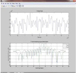
Figure 2: Transmits beamforming using uncorrelated waveform NT=16 azimuth angle 300 and 450
The figure 2 shows plots for each beamformer direction. One plot has the expected maximum gain at 30° and the other at 45°. The nulls at –60° and 60° arise from the fundamental property of the Beamformer in suppressing power in all directions except for the arrival direction.
Figure 3 Construct a 16–element, half-wavelength-spaced line array. Choose two arrival directions of interest — one at 10° and the other at 20° azimuth. Assume both having 0° elevation. Specify a sensor spatial covariance matrix that contains signals arriving from –60° and 60° and noise at – 10 dB.
Figure 3:Transmits beamforming using uncorrelated waveform NT=16 azimuth angle 100 and 200
5. Transmits Beamforming Application
The design of a multi-rank transmits beamformer for MIMO radar depends on the radar mode of operation, power constraints, clutter characteristics, and so on. In this section we consider transmit beamforming for use during search and tracking.
5.1 Tracking A Single Target
Consider first the case where it is desired to track a single target at a known or estimated direction θ1. This is a
typical situation for radar operating in tracking mode. In order to maximize the SNR at the matched-filter output we want to maximize both the gain of the receive array (by pointing the beam at the target) and the gain of the transmit array P (θ1) = aT(θ1)HRsaT(θ1) This will be
achieved if aT(θ1) is the eigenvector corresponding to the
largest eigenvalue of Rs. Furthermore, the largest
eigenvalue will be maximized if Rs is the unit rank matrix Rs = w*1wT1. It follows, therefore, that w1 = aT(θ1)/׀aT(θ1) ׀, in which case P(θ1) = aT(θ1)aT(θ1)H. For a transmit array
© 2015, IRJET.NET- All Rights Reserved
Page 1716
windowed (or rectangular windowed) beamformer for the kth target is given by(18)
Where the factor of 1/ reflects the fact that transmit power is equally divided among the targets.
5.3 Search Mode
When the radar is operating in search mode the target directions are unknown. In this case the best strategy is to illuminate uniformly the angular sector of interest. This can be accomplished by generating a “fan” of beams jointly covering the sector of interest. In phased-array radar these beams will be scanned. A MIMO radar can transmit on all beams simultaneously using a set of orthogonal waveforms. In other words, we use a multi-rank beamformer, where the rank equals the number of beams needed to cover the sector of interest.
6. CONCLUSION AND FUTURE SCOPE
In this paper we presented an approach to transmit beamforming and receiver design based on the design of uncorrelated waveform and complex MVDR weights rather than the design as done in previous work. Our proposed beamforming techniques having advantages of Spatial (beamformer) and temporal (waveform) parts of the problem eliminated, High SNR of match detector possible, we can obtain multiple independent measurements about the target, a better detection performance can be obtained, a better spatial resolution can be obtained. It is applicable for both in tracking mode and in search mode beamforming.
The Fundamental property of the proposed Beamformers in suppressing power in all directions except for the arrival direction and better cancellation of side lobes. It is applicable for both in tracking mode and in search mode beamforming. Because of the relative simplicity and transparency of the approach described in this project we believe that it is useful as a reference to alternative transmit beamforming methods.
Future Scope
The concept of virtual array is the key for increasing the spatial resolution in MIMO radar. We have obtained the virtual array through the transmission of orthogonal waveforms and match filtering. However, transmitting orthogonal waveforms decreases the processing gain. There may exist some better approach to obtain the virtual array resolution without compromising the processing gain. This topic is also worthy of further investigation.
REFERENCES
[1] Benjamin friedlander, “On transmit beamforming for mimo radar” fellow, IEEE University Of California santacruzieee transactions on aerospace and electronic systems vol. 48, no. 4 October 2012
[2] Nilesh Bhavsar ,A.J.Vyavahare “ Transmits beamforming design model for MIMO Radar” IJAREEIE volume 2,
[7] Okkonen J. “Uniform linear adaptive antenna array beamforming implementation with a wireless open- access research platform. University of Oulu,
Department of Computer Science and Engineering. Master’s Thesis, 58 pg, 2013.
[6] Radar Handbook by Merrill Skolnik Second edition [7] Steven M.Kay “Fundamental of Statistical Signal Processing Estimation Theory “ Pearson volume -I [8] Guang Hua, Saman S. Abeysekera “colocated mimo radar
transmit beamforming using orthogonal Wavform “IEEE 2012
[9] Merrill I.Skolnik “ Introduction to Radar Sytem “ Mcgraw-hill international edition.
[10] Adaptive space time beamforming in radar system ,World scientific book ,February 12,2013
[11] www.wikipedia/beamforming .xtml
© 2015, IRJET.NET- All Rights Reserved
Page 1717
BIOGRAPHIES
Nilesh Bhavsar received B.E
Degree from Government
college of engg Jalgaon in 2009
.He is currently working
towards the MTech in degree at the PES’S COE, Pune from Pune University. His research interests are in the area of radar and satellite signal Processing.
Dr..Arati J. Vyavahare received PhD degree in Image Processing in 2014. She has 15 years of teaching experience
and 4 years indusial
experience, Currently working as Professor and Research coordinator in PES’s Modern COE Pune in Electonics and Telecommunication
department. Her research area Is in Biomedical color image
segmentation and signal
processing.
Swati Gawhale received ME degree in Digital System in 2012.she has 5 year teaching experience .Curreently she is working as Assistant Prof. in Bharti COE pune Her research
interest in digital signal