R E S E A R C H
Open Access
Subspace-based self-interference
cancellation for full-duplex MIMO transceivers
Ahmed Masmoudi
*and Tho Le-Ngoc
Abstract
This paper addresses the self-interference (SI) cancellation at baseband for full-duplex MIMO communication systems in consideration of practical transmitter imperfections. In particular, we develop a subspace-based algorithm to jointly estimate the SI and intended channels and the nonlinear distortions. By exploiting the covariance and
pseudo-covariance of the received signal, we can increase the dimension of the received signal subspace while keeping the dimension of the signal subspace constant, and hence, the proposed algorithm can be applied to most of full-duplex MIMO configurations with arbitrary numbers of transmit and receive antennas. The channel coefficients are estimated, up to an ambiguity term, without any knowledge of the intended signal. A joint detection and ambiguity identification scheme is proposed. Simulation results show that the proposed algorithm can properly estimate the channel with only one pilot symbol and offers superior SI cancellation performance.
Keywords: Full-duplex communication, SI suppression, MIMO, parameter estimation, Subspace method, Second-order statistics
1 Introduction
Half-duplex transmission is commonly used in the current communication systems by transmitting and receiving over orthogonal channels. Full-duplex communication represents an attractive alternative to save channel resources or to increase the transmission efficiency. The main deterrent to employ full-duplex is the large self-interference (SI) from the simultaneous transmission and reception over the same frequency band. The SI is usually several orders of magnitude higher than the intended sig-nal received from the other transmitter, because the later travels a longer distance than the former signal. Recent works have shown that, using different cancellation stages, the SI can be sufficiently suppressed to properly detect the intended signal [1, 2].
The SI is first cancelled at the radio-frequency (RF) level, prior to the low-noise amplifier (LNA) and the analog-to-digital converter (ADC), to avoid overload-ing/saturation of these devices [1–3]. In other words, the SI should be sufficiently suppressed at RF to maintain the receiver’s limited dynamic range. Then, further SI sup-pression can be done after the ADC at the baseband [4, 5].
*Correspondence: [email protected]
Department of Electrical and Computer Engineering, McGill University, Montreal, Quebec, Canada
In the following, we assume that a cancellation stage at RF is available and we concentrate on the SI cancellation in the baseband.
To further reduce the SI, channel state information of the interference link should be available. Therefore, esti-mating the SI channel is a critical issue in full-duplex systems. In [6], the SI channel estimation is performed in the frequency domain using a least square (LS) technique. LS and minimum mean square error (MMSE) channel estimations are proposed in [7] to estimate the SI chan-nel in the relay station. However, these approaches ignore the intended signal coming from the other transceiver and treat it as additive noise. An adaptive least mean square algorithm to estimate the SI channel is proposed in [8] where the large SI compared to the intended signal and additive noise is exploited to obtain an estimate of the SI channel. A more elaborate LS-based estimator was pre-sented in [9] where a first estimate of the SI channel is obtained by considering the intended signal as additive noise. Then an iterative detection of the intended signal and channel estimation is performed to obtain a better estimate of the channel. On the other hand, spatial domain cancellation attempts to reduce the SI by precoding at the transmit chain and decoding at the receive chain. Spa-tial domain cancellation is formulated in the frequency
domain [10–12]. An alternative time domain formulation was presented in [13] by precoding the transmitted SI to coincide with the null space of the SI channel. These tech-niques are based on the knowledge of both the SI and intended channels at the two transceivers, which further motivates the development of channel estimators for full-duplex systems. A novel cancellation method is proposed in [14] by adding a cancelling signal to the original signal.
In addition to the SI channel information for SI cancella-tion, intended channel knowledge is an important prereq-uisite for signal detection. Motivated by this fact, channel estimation has been the subject of intense research. In the case of data-aided transmissions, training-based tech-niques can be applied [15, 16]. However, the amount of training increases dramatically with the number of anten-nas and channel order. Blind approaches have been pro-posed as more bandwidth efficient techniques [17, 18] where subspace methods, initially presented in [19], have a great potential. By decomposing the covariance matrix of the received signal, subspace methods exploit the orthog-onality between the noise and the signal subspaces in the observation space to express the channel coefficients as a linear combination of a basis of the signal subspace. Although previous researches have shown the potential of this procedure to give an accurate estimate of the channel, it remains of limited practical interest. Actually, considering that the noise subspace needs to be nonde-generated, it is legitimate to wonder how we can satisfy this condition. Previous works rely on oversampling of the received signal or using more receive antennas than trans-mit antennas [20, 21]. However, such solutions increase the receiver cost and need additional hardware. More-over, they may result in correlated noise which makes the subspace technique inappropriate. A maximum likelihood estimator was presented in [22] by exploiting the pilots in the intended signal.
In the full-duplex context, the transmitter impair-ments, including power amplifier (PA) nonlinearity and IQ mixer imbalance, become limiting factors and need to be reduced to properly detect the intended signal. In practice, the inband image resulting from the IQ mixer in mobile user is about 28 dB lower than the direct signal [23]. In the presence of strong SI of about 50 dB higher than the intended signal, this IQ image represents addi-tional interference for the intended signal. The effects of transceiver impairments are illustrated in detail in [3, 24]. Due to the importance of the nonlinearities, a dig-ital cancellation procedure has been proposed to reduce the effects of the PA in [25] by estimating the nonlin-ear coefficients of the PA and another algorithm has been proposed to deal with the IQ mixer imbalance [26]. However, there is no discussion about the intended sig-nal in the existing literature, which limits the estimation performance if it is considered as additive noise.
In this work, we incorporate the intended signal in the estimation process. We also take into account the transmitter impairments when modelling the SI signal. For realistic multipath propagation channels, we need to estimate the SI channel, the intended channel and the dis-torted SI. And noting that the intended signal is unknown, we propose to use a novel subspace method to efficiently estimate the different parameters. Since the received sig-nal consists of the SI and intended sigsig-nals, the dimension of the signal subspace in full-duplex operation is at least twice that in traditional half-duplex operation [5, 27]. Thus an essential shortcoming of the existing subspace-based technique is that it can be applied only when the number of receive antennas is larger than the number of transmit antennas. In the following, we circumvent this condition and develop a subspace-based algorithm suit-able for MIMO full-duplex systems with larger or equal numbers of transmit and receive antennas. We exploit both the covariance and pseudo-covariance matrices of the received signal to effectively increase the dimension of the observation space while keeping the dimension of the signal subspace unchanged. The joint processing of the received signal and its complex conjugates has been used in many works to improve the detection performance on various systems [28, 29]. Also, in an entirely differ-ent context, the improper property of the received signal was first exploited for channel identification in [30] to obtain a virtual SIMO model from a SISO one. Prelimi-nary results can be found in [31] for real-valued symbols to enable the application of widely linear processing tech-niques, but entail a loss in spectral efficiency compared to complex-valued symbols. We propose in this paper a method to use the widely linear processing to complex symbols by forcing the transmit signal to be improper. We justify the advocated time domain approach and com-pare its performances to a frequency domain approach and we generalize the PA model to any nonlinearity order. In practice, we cannot blindly recover the channel coeffi-cients since an ambiguity term always appears in the final estimate [5]. This ambiguity is resolved using a sequence of pilot symbols, considerably shorter than needed in training-based techniques. In the following, we propose a joint data detection and estimation of the ambiguity term to considerably reduce the length of the pilot sequence. We show through simulation that just one pilot symbol is sufficient to perfectly estimate the channel.
The paper is organized as follows. In Section 2, the full-duplex system model is presented. The subspace-based channel estimation is described in Section 3. In Section 4, we describe the joint decoding and ambigu-ity removal procedure. Illustrative simulation results are given in Section 5 and Section 6 presents the conclusion.
and conjugate transpose for matrices or vectors, respec-tively. For a given vector x, diag(x) returns a diagonal matrix whose diagonal elements are the entries of x. rank(M) returns the rank of a given matrix M, det(M) returns the determinant of M and vect(M) stacks the columns ofMinto one vector. The operator⊗refers to the Kronecker product of two matrices.(·)and(·)return the real and imaginary parts of complex numbers. E(·)
denotes the mathematical expectation.|| · ||2returns the Euclidean norm of a vector.Iprefers to thep×pidentity matrix and1pthep×1 vector with 1 at all elements. A term accented by a hat,x, means an estimate ofx.
2 Full-duplex MIMO system model
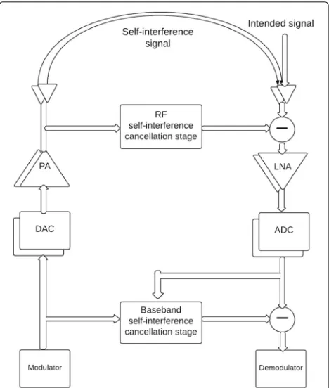
Consider two transceivers communicating in a full-duplex fashion. The simultaneous transmission and reception creates self-interference (SI) to be cancelled before the demodulation process. The SI signal is first suppressed at RF, prior to the low-noise amplifier (LNA) and analog-to-digital converter (ADC) to avoid overloading/saturation of these components [2, 3, 32]. In [5], we proposed an effi-cient compressed-sensing (CS)-based algorithm for the RF SI cancellation stage. In this work, we concentrate on the development of subspace-based algorithm to jointly estimate the SI and intended channels and the nonlin-ear distortions for the baseband SI cancellation stage of a full-duplex MIMO transceiver with arbitrary numbers of transmit and receive antennas. The output signal of the RF SI cancellation stage consists of the residual SI, the intended signal received from the other transceiver and the additive thermal noise. Figure 1 shows a simplified block diagram of a MIMO transceiver. The residual SI can be further suppressed at the baseband after ADC using digital signal processing (DSP). The advantage of working in the digital domain, as compared to RF, is that sophisti-cated DSP methods can be handled. Both transceivers are equipped withNttransmitting antennas andNrreceiving antennas. At transmitting antennaq, a group of N data symbolsXq =[Xq(0),. . ., Xq(N−1)]T is first modulated by the IFFT matrix to form an OFDM block, then the time domain vectorxq =[xq(0),. . ., xq(N −1)]T is extended by the cyclic prefix of length1Ncpand the resulting vector is sent sequentially. In the transmit streamq, the complex signalxq(t)after the digital-to-analog conversion (DAC), is passed through an imbalance IQ mixer whose output is as follows:
xIQq (t)=k1,qxq(t)+k2,qx∗q(t), (1)
wherek1,qandk2,q are the responses of the IQ mixer at antennaqto the direct signal and the image, respectively. Then, the signal is amplified with a nonlinear PA. In the
Fig. 1Simplified block diagram of the full-duplex transceiver with RF and baseband SI cancellation stages
following, we model the PA response with a Hammerstein model whose response is:
xPAq (t)= ⎛ ⎝P
p=0
α2p+1,qxIQq (t)|xIQq (t)|2p ⎞
⎠f(t), (2)
where α2p+1,q, for p = 0,. . ., P, are the nonlinearity coefficients of the PA at transmit antennaq,Pis the non-linearity order andf(t)is the memory of the PA. In (2), denotes the convolution operator. The transmitted sig-nal is coupled to produce SI in the receiver. Considering multipath channels, the received signal at antennaris as follows:
yantr (t)= Nt
q=1
hcr,q(t)xPAq (t)+ Nt
q=1
hsr,q(t)sq(t)+wth,r(t), (3)
Rx streamr. To reduce the SI before the LNA and ADC, the RF cancellation stage is performed as follows:
yRFr (t)=yantr (t)− the SI to the main propagation path. To include the trans-mitter distortion in the RF cancellation process, the ref-erence signal is taken from the output of the PA. This RF SI cancellation can attenuate the SI by 30 dB, as reported in practical experiments [6, 33]. Then, the received signal passes through the LNA:
yLNAr (t)=kLNAyrRF(t)+wLNA(t), (5)
where wLNA(t)is the additive noise caused by the LNA andkLNAis the gain of the LNA. Finally, the received sig-nal is adjusted by the variable gain amplifier (VGA) to match the dynamic range of the ADC. For simplicity, we suppose that the linear gainsk1,qandα1,qof the IQ mixer and PA are equal to 1. Combining (2), (3) and (5), the received samples are given by
yr(n)= linearity and wr(n) collects the thermal noise, the LNA noise and the quantization noise. In (6), the global channel responses are given by
h(ri,)q(l) = kLNA(hcr,q(l) f(l)−hcr,q(l)),
h(rs,q)(l) = kLNAhsr,q(l). (7) To have a homogeneous notation, all channels are sup-posed to have the same orderLand the channels of order lower thanLare zero-padded so that the different chan-nels have the same order andLstill satisfiesL<Ncp. The received vector y(n) =[y1(n),. . ., yNr(n)]T over theNr
antennas is given by
y(n)=
the transmitted signals from theNtantennas to obtain
y(n)= all the channel coefficients in the followingNrM×2NtN block Toeplitz matrix:
The received OFDM block on theNrantennas is:
y=[yT(0), yT(1),. . ., yT(M−1)]T=Hu+w, (14)
whereM=N+L, the 2NtN×1 data vectoruis given by
u=[xT(0), sT(0),. . ., xT(N−1), sT(N−1)]T, (15)
and
w=[wT(0), wT(1),. . ., wT(M−1)]T. (16)
3 Subspace-based channel estimator
We propose to apply a subspace-based algorithm to jointly estimate the SI and intended channel coefficients along with the nonlinear coefficients. Subspace methods rely on the orthogonality property between the signal and noise subspaces. These two subspaces are obtained from eigen-decomposition of the covariance matrix of the received signaly. Denoting byRu, the covariance ofu, the covari-ance matrixRyof the received vectoryis given by
Ry=HRuHH+σ2IMNr, (17)
as long as the signal samples are uncorrelated from the noise samples2.
The signal subspace is spanned by the columns of the matrix H. Noting that the columns of H are, by con-struction, linearly independent as soon as there exists an
l ∈[0, L] such thatH(l)is full rank3, the matrixH is a full-rank matrix. Therefore, the dimension of the signal subspace is 2NNt. It follows that, to obtain a nondegen-erate noise subspace, its dimensionNrM−2NtN should be larger than zero, and thus, the number of receiving antennas should be larger than the number of transmitting antennas to make the subspace method work, and in [5], we developed the linear subspace algorithm for this set-ting. In the following, we will develop the subspace-based algorithm for general numbers of transmit and receive antennas. WhenNt=Nr, the matrixRycannot be directly used to find the noise subspace. As an alternative different approach, we consider the augmented received vector as
y=
The use of the augmented received vector is usually referred as widely linear processing. In this case, the augmented covariance matrixRy ofyhas the following structure:
Ry=HRuHH+σ2I2MNr, (19)
whereRudenotes the covariance matrix of the augmented
transmit signalu=
It is worth mentioning that the proper noise has a van-ishing pseudo-covariance [34]. The main purpose of using the extended received signal is to increase the dimension of the received signal and thus avoid the degenerate noise subspace. Hence, the subspace identification procedure can be derived only if the signal part covariance matrix, given byHR uHH, of the covariance matrixRyis singular. It results thatds = rank(HR uHH) <2MNr. In this case, the signal is confined in ads-dimensional subspace and the remaining noise subspace is with dimension 2MNr−ds.
Singularity ofRuis a necessary condition to obtain a non-degenerate noise subspace. Actually, noting thatHis full rank, nonsingularRu results in rank(HR uHH) = 2MNr, and thus, the matrixHR uHH spans all the observation space. On the other hand, since the matrix H is a tall matrix, singularity ofRu is not a sufficient condition to guarantee the singularity ofHR uHH.
The matrix Ru can be expressed in a block form in terms of the covariance matrix of u, Ru = E(uuH), the pseudo-covariance matrix Cu = E(uuT) and their complex conjugates as
In the following, we distinguish two cases of real and complex modulated symbols.
For real modulated symbols, it can be shown thatRu= α2M ⊗I
From (22), we note that each column of M appears exactly two times (the first column ofMis the same as the (N+1)thcolumn, and theithcolumn ofMis the same as the(2N−i+2)thcolumn, fori=2,. . .,N). Therefore, the matrixM has exactlyN-independent columns and thus its rank is N. It follows that the rank of Ru is 2NNt. In Appendix 1, we show that Ru has zero eigenvalue with multiplicity 2NNt and 2α2 also with multiplicity 2NNt. Then, the matrixRuis decomposed asUDUH whereDis the 4NNt×4NNtdiagonal matrix with zeroes in the first 2NNtdiagonal elements and 2α2in the last 2NNtdiagonal elements andU is an orthogonal matrix whose columns are the corresponding eigenvectors ofRu.
For complex symbols, the pseudo-covariance matrixCu is generally equal to the zero matrix, which makes the matrixRu of full rank. To avoid this problem, we apply a simple precoding at the input of the IFFT. It transforms the data symbolXqto
Xq=PXq+QX∗q. (23)
the matricesPandQso that the covariance matrixRuhas rank 2NNtand can be decomposed asUDUH withDas the 4NNt×4NNtdiagonal matrix with zeroes in the first 2NNtdiagonal elements.
The noise subspace is the span of thep=2MNr−2NNt eigenvectors of Ry corresponding to the smallest eigen-valueσ2, and the columns ofHR uHHbelong to the signal subspace. Due to the orthogonality between the signal and the noise subspaces, each column ofHR uHH is orthogo-nal to any vector in the noise subspace. Let{νi}pi=1denote the p co-orthogonal eigenvectors corresponding to the smallest eigenvalue ofRy. Then we have the following set of equations:
νH
i HR uHH =0, i=1, 2,. . ., p. (24) From (24), we conclude thatνispans the left null space ofHR uHH. For convenience,U is written as a block of 4
Rucorresponding to the eigenvalue zero and the columns of [UT2, UT4]T are the other eigenvectors. Then, taking into account the eigenvalue decomposition ofRu, the set of equations in (24) are equivalent to
νH specific structure ofHshould be taken into consideration when solving the equations in (27) to obtain a more accu-rate estimate of the channels. To that end, we divide the two vectorsνi,1andνi,2as follows: previous notations, (27) is rearranged to obtain
ˇ
hTVTi,1U2+hˇ H
VTi,2U4=0, (31) or, by taking the transpose of the previous equation:
UT2Vi,1hˇ+UT4Vi,2hˇ
∗
=0, (32)
fori=1, 2,. . ., p. Note that the difference between (27) and (32) is that (32) takes into account the Toeplitz blocks structure ofH. Now, collecting all the previous equations, we obtain
Separating the real and imaginary parts of (33), we have
corresponding to the zero eigenvalue. Therefore, an esti-mate ofhis given by
h=c, (36)
where=[β1, β2,. . ., β4NtNr], and the 4NtNr×1 vec-torcrepresents the ambiguity term to be estimated. The complex channel vector can also be obtained as
hˇ =c, (37)
whereis obtained by combining the lines ofin the following way:
We mention that the matricesU2andU4do not depend
on the received signal and can be computed offline prior to the transmission. It is also seen that the overestimated channel orderL does not affect the estimation process. This is a common property with other subspace-based estimators [17].
4 Resolving the ambiguity term
As mentioned above, the subspace that contains the channels is obtained and the ambiguity term needs to be estimated to extract the exact coefficients. Different approaches can be applied to solve the ambiguity term c. To do so, we highlight the contribution of c on the received vectory. First, we separate the matrixin two
NtNr(L+ 1) × 4NtNr matrices i and s which con-tribute in the SI and intended channels, respectivelyi.e.,
ˇ
h(i) = icandhˇ (s)
= sc
. By rearranging the elements ofias matricesH(i)andi, respectively, having the same block structure asHin (13).
Next, we define the diagonal matricesK andApwhose diagonal elements are k =[k2,1,. . ., k2,Nt]T andαp =
Ap)xip,pin terms of the transmitter impairments, one can express the received signal in (14) as
y=i(INNt⊗c) some manipulations, one can easily verify that (INNt ⊗
c)xi=(xi⊗I4NtNr)cand(INNt⊗c)s=(s⊗I4NtNr)c. Then,
the received vector in (41) is rewritten as
y=i
In (42), the received vector y is expressed as a linear function of the unknown vectorc. This formulation makes the estimation ofc more tractable. While the transmit-ted SI is known, the distortransmit-ted parts(IN ⊗Ap)xip,p and (IN ⊗K)x∗i of the SI from the cascade of the IQ mixer and PA need to be estimated. We begin by writing the fol-lowing cost functionf(c,s,K,Ap)= ||y−i((xi+(IN⊗ procedure until the estimated parameters converge. An initial estimate ofcis obtained using the LS criteria as
c0=(i(xi⊗I4NtNr))#y, (43)
where the operator (·)# returns the pseudo-inverse of a given matrix. At the kth iteration, the estimatec
obtained at the previous iteration is used to finds,Kand the frequency domain and each element of the frequency domain vector is projected to its closest discrete constel-lation point. The obtained vector is converted back to the time domain to obtain a better estimateskofs.
Then, an update ofcat iterationkis obtained as:
ck=
If a set ofPpilot, pilot symbols are available at subcarriers indexed by P = {p1,. . ., pPpilot}, the intended transmit signal at antennaqcan be represented as the sum of two signals:
where the first sequencespq(n)contains the pilot symbols and the second sequencesdq(n)contains the unknown data symbols transmitted by other intended transmitter. Then, the received vector in (42) is rearranged as follows:
y=i and contain the pilot symbols and unknown symbols,
respectively. The initial estimate ofcis modified to incor-porate the pilot symbols as
c0=
As before,sdk is converted to the frequency domain, demodulated then transformed to the time domain to obtainsdk. The updated estimate of c at iteration k is
In the following, we summarize the different steps of the proposed algorithm:
1. Compute the augmented covariance matrixRyby time averaging ofT received samples as:
Ry=
2. Perform eigendecomposition ofRyand take thep eigenvectorsνicorresponding to the smallest eigenvalue ofRy.
3. Construct the matrixfromνiand compute the 4NtNrsingular vectors ofcorresponding to the zero singular value to form.
4. Build the matricesˇiandˇsas given in (39).
5 Simulation results
In this section, we provide some simulation results on the performance of the proposed estimation algorithm for a 2×2 MIMO full-duplex system. The transmitted bits are mapped to 4-QAM symbols, then passed through an OFDM modulator of lengthN=64. The wireless channel is represented as a Rayleigh multipath fading channel with five equal-variance resolvable paths. Since the exact num-ber of paths is supposed to be unknown, the algorithm is parametrized as if there are eight paths. In the following, the SNR is defined as the average intended-signal-to-thermal noise power ratio and the estimation mean square error (MSE) ofHis MSE=E||H−H||2. To model the RF impairments, a complete transmission chain is simu-lated. The PA coefficients are derived from the intercept points by taking the IIP3 = 20 dBm. For the IQ mixer, the ratio between the direct signal and the image is set to 28 dB which is specified in 3GPP LTE specifications [23]. The ADC is modelled as a 14-bit quantizer to incorpo-rate the quantization noise. Therefore, no simplifications are made regarding the different impairments. Antenna separation can attenuate the SI by 40 dB while the RF can-cellation stage reduces the direct path by 30 dB [1] leaving the weaker reflections and transceiver impairments to be reduced by the proposed digital algorithm.
The proposed algorithm is compared to different chan-nel estimators: the least square (LS) and the maximum likelihood (ML) algorithms. For the LS estimator, the channel coefficients are obtained using the knownself sig-nal and the pilot symbols in the intended sigsig-nal. It simply considers the unknown symbols as additive noise. The ML estimate is obtained by maximizing the following cost function:
L
H(i), H(s)
=log(det(R))−
y−H(i)x−H(s)sp H
×R−1
y−H(i)x−H(s)sp
,
whereR=α2H(s)HH(s)+σ2INrM. An iterative procedure
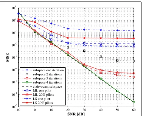
to find the ML estimate was proposed in [35]. The covari-ance matrix is obtained by averaging 60 OFDM blocks. Figures 2 and 3 plot the MSE vs. SNR curves for the SI and intended channel estimations, respectively. In both figures, one pilot symbol, from the intended transceiver, is used to solve the ambiguity matrix. For comparison purpose, a perfect estimate of the ambiguity term c is obtained ascperfect = arg minc||hˇ−c||22and the corre-sponding curves are labelled by clairvoyant subspace. It is seen that, when one pilot symbol is used in the ML and LS estimators, the proposed subspace algorithm offers notably lower MSE over a large SNR range. We also repre-sent the performance of the ML and LS estimators when 20% of the transmit symbols are known (pilot symbols equally spaced within one OFDM symbol) while keeping
−10 0 10 20 30 40 50 60
10−7 10−6 10−5 10−4 10−3 10−2 10−1 100 101
SNR [dB]
MSE
subspace one iteration subspace 2 iterations subspace 3 iterations subspace 4 iterations clairvoyant subspace ML one pilot ML 20% pilots LS one pilot LS 20% pilots
Fig. 2SI channel estimation MSE vs. SNR with 60 received OFDM symbols
one pilot symbol for the subspace method4. In this case, the three algorithms give comparable performance at low SNR region with the expanse of lower bandwidth effi-ciency. As the SNR increases, the performance of the LS and ML estimators saturate due to the reduced number of pilot symbols and the presence of the unknown trans-mit signal from the intended transceiver which acts as an additive noise. While the subspace algorithm exploits the information bearing in the unknown data to find the signal subspace. The ambiguity term is first solved using the known transmit symbols, then the iterative decoding ambiguity estimation is applied to improve the estimation performance. From Figs. 2 and 3, three to four iterations
−10 0 10 20 30 40 50 60
10−8 10−6 10−4 10−2 100 102 4 10
SNR [dB]
MSE
subspace one iteration subspace 2 iterations subspace 3 iterations subspace 4 iterations clairvoyant subspace ML one pilot ML 20% pilots LS one pilot LS 20% pilots
are sufficient to converge and the performance is close to the performance when the ambiguity termc is perfectly obtained. Note that the ML solution is also obtained in an iterative way and for a fair comparison; we simulate the performance of the ML estimator after four iterations. As it can be expected, the estimate of the SI channel is more accurate than the estimate of the intended channel. This can be explained by the fact that the self-signal is known while one pilot symbol is known in the intended signal.
The number of pilot symbols is a critical issue in chan-nel estimation since a large pilot sequence provides better estimation performance but reduces the bandwidth effi-ciency of the system. In Figs. 4 and 5, we compare the impact of the number of pilot symbols on the perfor-mance of the three estimators. We periodically place the pilot symbols within an OFDM symbol. Optimal pilot placement requires to verify allPpilot combinations from
N subcarriers and hence, leads to an NP-hard problem beyond the scope of this paper, and is left for future work. It can be seen from these figures that the subspace method is not greatly affected by the number of pilot symbols since the subspaces are obtained using the second-order statis-tics of the received signal and not the transmit signal itself. Clearly, the proposed algorithm outperforms the ML and LS estimators at a reduced number of pilots while this tendency is inverted when the number of pilots increases. However, a system with a large amount of pilot symbols is not of practical interest.
In Figs. 6 and 7, we evaluate the impact of the number of observed OFDM symbols on the estimation performance. For the three algorithms, we consider the transmission scheme where the number of pilot symbols is set to one and the SNR is 10 dB. As the subspace algorithm is based
0 5 10 15 20 25 30 35 40 45 50
10−3 10−2 10−1 100 101
percentage of pilot symbols
MSE
Subspace estimator ML estimator LS estimator
Fig. 4SI channel estimation MSE vs. percentage of pilot symbols for SNR = 10 dB
0 5 10 15 20 25 30 35 40 45 50
10−3 10−2 10−1 100 101 102 103 104
percentage of pilot symbols
MSE
Subspace estimator ML estimator LS estimator
Fig. 5Intended channel estimation MSE vs. percentage of pilot symbols for SNR = 10 dB
on estimates of the second-order statistic of the received signal, its performance varies with the number of OFDM symbols. All three algorithms are able to estimate the SI channel with an error floor for the LS. The ML and sub-space algorithms offer the similar performance. On the other hand, the LS estimator fails to recover the intended channel, for any number of OFDM symbols. This can be explained by the fact that the number of unknowns (intended channel coefficients) is larger than the num-ber of pilot symbols. Hence, it is not possible to use this method when the number of pilot symbols is small. The ML estimator presents also poor estimation performance for the intended channel, while the subspace method is
15 30 45 60 75 90 105 120 135 150
10−3 10−2 10−1 100 101 102
Number of OFDM symbols
MSE
subspace one iteration subspace 2 iterations subspace 3 iterations ML estimator LS estimator
15 30 45 60 75 90 105 120 135 150 10−4
10−3 10−2 10−1 100 101 102 103 104 105
Number of OFDM symbols
MSE
subspace one iteration subspace 2 iterations subspace 3 iterations ML estimator LS estimator
Fig. 7Intended channel estimation MSE vs. number of OFDM symbols for SNR = 10 dB and one pilot symbol
able to return a good channel estimate, with a better bandwidth efficiency compared to the other estimators, as soon as there are enough OFDM symbols to compute the covariance matrix.
Our primary motivation of this work is to develop an accurate channel estimator to cancel the SI signal. The performance of the SI-canceller are represented by its achieved output signal-to-residual-SI-and-noise power ratio (SINR) after SI cancellation vs. the input SNR. Ide-ally, if SI could be completely cancelled then the residual SI after cancellation is 0, and consequently, the output SINR equals the input SNR as shown by the dashed line “per-fect cancellation” in Fig. 8. In other words, the “per“per-fect
0 10 20 30 40 50 60
−30 −20 −10 0 10 20 30 40 50 60
SNR [dB]
SINR [dB]
subspace one iteration subspace 2 iterations subspace 3 iterations frequency domain LS 20% pilots frequency domain LS one pilot widely−linear LS perfect cancellation
Fig. 8Output SINR vs. input SNR after SI cancellation
cancellation” is considered as the ideal upper-bound for the SINR. As shown in Fig. 8, with three iterations, the proposed subspace-based SI-canceller can offer an out-put SINR very close to the upper-bound over a large SNR range. At low SNR, the large estimation error results in a larger residual SI after cancellation, which ultimately affects the output SINR.
We also investigate in Fig. 8 a frequency domain method to estimate the different parameter using the pilot sym-bols on some subcarriers. We resort to the LS estimator to find the channel responses at the pilot subcarriers. Since the remaining subcarriers contain unknown sym-bols from the intended transceiver, the complete channel responses are obtained by linear interpolation of the esti-mated coefficients. Thus, the frequency domain approach uses only the portion of the signal containing pilots while the proposed approach exploits the whole received signal through the second-order statistics. Clearly, the perfor-mance of the frequency domain approach highly depends on the number of pilots (as shown in Fig. 8) since the interpolation cannot model the variance of the channel in the frequency domain. We also compare the proposed method with the widely linear LS estimator in [26]. Note that the algorithm in [26] ignores the PA nonlineari-ties and does not incorporate the intended signal in the estimation process. Some time frames are dedicated to transmit orthogonal pilot symbols for estimation purpose, where the transceiver receives only its own signal. There-fore, the widely linear LS estimator incurs an overhead and requires synchronization between the two transceivers. Besides, it shows a noise floor at high SNR because the PA nonlinearity is not considered during the estimation pro-cess. On the other hand, by exploiting the whole received signal through its second-order statistics, the proposed method offers good performance even with one pilot and still outperforms the frequency domain approach (even with much larger number of pilots). Figure 9 plots the bit error rate (BER) vs. SNR curves of the two approaches. For comparison, we include the case of perfect chan-nel estimate. To improve the BER, the SINR should be kept as high as possible at the demodulator. To conclude, while the frequency domain approach is more intuitive, it needs a large number of pilots and is outperformed by the proposed method.
0 5 10 15 20 10−5
10−4 10−3 10−2 10−1 100
SNR [dB]
BER
subspace algorithm one pilot frequency domain LS 20% pilots frequency domain LS one pilot perfect channel
Fig. 9BER vs. SNR comparison of the proposed and the frequency domain LS techniques
The PA nonlinearity effects on the performance of the proposed algorithm are also investigated through simula-tions. Figure 12 plots the resulting SINR after cancellation vs. the value of the PA third-order intercept point (IIP3) for SNR= 20 dB. Forperfect cancellation, the resulting SINR after cancellation would be the SNR= 20 dB. A lower IIP3 indicates higher PA distortions (or poorer PA) and hence reduces the resulting SINR after cancellation. Figure 12 shows that as the IIP3 value increases, the cancellation performance is improved. However, for a sufficiently high IIP3 (e.g., 18 dBm or higher), the PA dis-tortions are no longer dominant and the resulting SINR
0 20 40 60 80 100
8 9 10 11 12 13 14 15 16
Oscillator 3 dB bandwdith f
3dB [Hz]
SINR [dB]
first iteration second iteration third iteration
Fig. 10SINR after SI cancellation vs.f3dB
0 20 40 60 80 100
10−5 10−4 10−3 10−2 10−1 100
Oscillator 3 dB bandwdith f
3dB [Hz]
BER
first iteration second iteration third iteration perfect channel
Fig. 11BER vs. phase noisef3dB
after cancellation is unchanged. This can be explained by the fact that, when developing the algorithm, the third-order component of the signalxq,ip3(n)=xqIQ(n)|xIQq (n)|2 is approximated by xq(n)|xq(n)|2 to simplify the algo-rithm. This approximation only affects the algorithm performance when the nonlinear coefficients are sufficiently high.
6 Conclusions
In this paper, a subspace-based estimation has been pro-posed to jointly estimate the SI channel, the intended channel and the transmitter impairments for MIMO full-duplex systems. By exploiting the covariance and
10 12 14 16 18 20 22 24 6
8 10 12 14 16 18 20 22 24
IIP3
SINR [dB]
first iteration second iteration third iteration perfect cancellation
pseudo-covariance matrix of the received signal, an effective way has been formulated to apply the sub-space method for symmetric MIMO systems. The com-plete characterization of the second-order statistic of the received signal avoids the need of oversampling, required in traditional subspace methods. The subspace that con-tains the channels is blindly estimated and a short pilot sequence is needed to extract the channel coefficients from this subspace. The proposed method dramatically reduces the number of pilot symbols needed to identify the channel coefficients. Simulation results show that one pilot symbol is enough to obtain an accurate estimate while other methods are not able to recover the channel.
Endnotes
1The length of the cyclic prefix N
cp should be larger than the delay spread of the channel to eliminate the inter-symbol interference and inter-carrier interference. Therefore, if we know the length of the channel, we can set the cyclic prefix to be sufficiently large to satisfyNcp >L. Since this information is in general not available,Ncp is chosen to guaranteeNcp >L. For example, if the distance between the two transceivers is 1 km, a cyclic prefix of 4 microsec is sufficient.
2Physically, the additive noise arises from the thermal
agitation of the charge carriers in an electronic device and is independent from the input. It can also contain interfer-ence from other systems whose signals are independent from the transmit signal of the considered system.
3The previous condition is verified for independent
channels between different antennas.
4The pilot symbols are equally spaced within one
OFDM symbol.
Appendix 1: Eigenvalues ofRu
Following the discussion in Section 3, we mention thatM is of rank N, then it has N strictly positive eigenvalues, τ1, τ2,. . ., τN, and eigenvalue 0 of multiplicityN. And since the covariance matrix Ru is given by α2M⊗I2Nt,
it follows thatRu has alsoN eigenvalues τ1, τ2,. . ., τN each of multiplicity 2Nt and eigenvalue 0 of multiplic-ity 2NNt. To find the non-zero eigenvalues, we solve the characteristic polynomial ofMgiven by
detM−τI2N
=0. (51)
First, ifτ = 1 is an eigenvalue of M, then it exists a vectora=0such thatMa−a=0. It follows thata(1)= a(2) = · · · = a(2N) = 0, which is in contradiction with a=0. Therefore, 1 is not an eigenvalue ofM.
By writingMas a block matrix:
M=
IN M1,2 M1,2 IN
, (52)
the characteristic polynomial ofM, forτ =1, is written as
det(M−τI2N)=det((1−τ)IN)
×det(1−τ)IN−M1,2(1−τ)−1INM1,2 =(1−τ)N1−τ−(1−τ)−1N,
(53)
where we used the fact thatM1,2M1,2 = IN. Then, the solutions to detM−τI2N
=0 are 0 and 2. Therefore, all non-zero eigenvalues ofMare equal to 2 and thus all the non-zero eigenvalues ofRuare equal to 2α2.
Appendix 2: Precoding for complex modulation To make it simple, we consider the matrices P and Q having the following block structure:
P=
aIN/2 0IN/2 0IN/2 bIN/2
,
Q=
0IN/2 cIN/2
dIN/2 0IN/2
, (54)
for given real numbersa,b,candd. Similarly to the real modulation, we haveRu=M⊗I2NtwhereMfor complex
modulation is given by
M=
PPT+QQT PQT+QPT PQT+QPT PPT+QQT
= ⎛ ⎜ ⎜ ⎝
(a2+c2) 0 0 (ad+bc)
0 (b2+d2) (ad+bc) 0 0 (ad+bc) (a2+c2) 0 (ad+bc) 0 0 (b2+d2)
⎞ ⎟ ⎟ ⎠⊗IN/2,
fora2+c2 = b2+d2. Thus, fora,b,canddsatisfying
a2+c2 = ad+ bcandb2+ d2 = ad+bc, each line ofMis repeated two times andRuhas rank 2NNt. As an example, we can takea= 0.757,b = 0.5032,c = 0.4935 andd=0.7506.
Acknowledgements
This work was supported in part by an R&D Contract from Huawei Technologies Canada and in part by a Grant from the Natural Sciences and Engineering Research Council of Canada.
Competing interests
The authors declare that they have no competing interests.
Received: 14 July 2016 Accepted: 23 February 2017
References
2. M Duarte, A Sabharwal, V Aggarwal, R Jana, KK Ramakrishnan, CW Rice, NK Shankaranarayanan, Design and characterization of a full-duplex multiantenna system for WiFi networks. IEEE Trans. Veh. Technol.63(3), 1160–1177 (2014)
3. A Masmoudi, T Le-Ngoc, inProc. IEEE Global Telecommun. Conf. Self-interference cancellation limits in full-duplex communication systems (IEEE, Washington DC, 2016)
4. MA Khojastepour, S Rangarajan, inProc. ASILOMAR Signals, Syst., Comput. Wideband digital cancellation for full-duplex communications (IEEE, Pacific Frove, 2012), pp. 1300–1304
5. A Masmoudi, T Le-Ngoc, Channel estimation and self-interference cancellation in full-duplex communication systems. IEEE Trans. Veh. Technol.66(1), 321–334 (2017)
6. M Duarte, C Dick, A Sabharwal, Experiment-driven characterization of full-duplex wireless systems. IEEE Trans. Wireless Comm.11(12), 4296–4307 (2012)
7. J Ma, GY Li, J Zhang, T Kuze, H Iura, inProc. IEEE Global Telecommun. Conf. A new coupling channel estimator for cross-talk cancellation at wireless relay stations, (Honolulu, 2009)
8. JR Krier, IF Akyildiz, inProc. IEEE Pers. Indoor and Mobile Radio Commun. Active self-interference cancellation of passband signals using gradient descent (IEEE, London, 2013)
9. S Li, RD Murch, inProc. IEEE Global Telecommun. Conf. Full-duplex wireless communication using transmitter output based echo cancellation, (2011), pp. 1–5
10. D Bliss, P Parker, A Margetts, inProg. IEEE Statistical Signal Processing. Simultaneous transmission and reception for improved wireless network performance, (2007), pp. 478–482
11. BP Day, AR Margetts, DW Bliss, P Schniter, Full-duplex bidirectional MIMO: achievable rates under limited dynamic range. IEEE Trans. Signal Process.
60(7), 3702–3713 (2012)
12. AC Cirik, J Zhang, M Haardt, Y Hua, inIEEE Workshop on Signal Processing Advances in Wireless Communications (SPAWC). Sum-rate maximization for bi-directional full-duplex MIMO systems under multiple linear constraints, (2014), pp. 389–393
13. Y Hua, P Liang, Y Ma, AC Cirik, Q Gao, A method for broadband full-duplex MIMO radio. IEEE Signal Process. Lett.19(12), 793–796 (2012)
14. A Masmoudi, T Le-Ngoc, inProc. IEEE Veh. Technol. Conf. Self-interference mitigation using active signal injection full-duplex MIMO-OFDM systems (IEEE, Montreal, 2016)
15. J-J Van de Beek, O Edfors, M Sandell, SK Wilson, P Ola Borjesson, inProc. IEEE Veh. Technol. Conf. On channel estimation in OFDM systems, (1995), pp. 815–819
16. H Minn, N Al-Dhahir, Optimal training signals for MIMO OFDM channel estimation. IEEE Trans. Wireless Comm.5(5), 1158–1168 (2006) 17. F Gao, Y Zeng, A Nallanathan, T-S Ng, Robust subspace blind channel
estimation for cyclic prefixed MIMO ODFM systems: algorithm, identifiability and performance analysis. IEEE J. Select. Areas Comm.26(2), 378–388 (2008)
18. C-C Tu, B Champagne, Subspace-based blind channel estimation for MIMO-OFDM systems with reduced time averaging. IEEE Trans. Veh. Technol.59(3), 1539–1544 (2010)
19. E Moulines, P Duhamel, J-F Cardoso, S Mayrargue, Subspace methods for the blind identification of multichannel FIR filters. IEEE Trans. Signal Process.43(2), 516–525 (1995)
20. Y Zeng, T-S Ng, A semi-blind channel estimation method for multiuser multiantenna OFDM systems. IEEE Trans. Signal Process.52(5), 1419–1429 (2004)
21. E de Carvalho, DT Slock, Blind and semi-blind FIR multichannel estimation: (global) identifiability conditions. IEEE Trans. Signal Process.
52(4), 1053–1064 (2004)
22. A Masmoudi, T Le-Ngoc, A maximum-likelihood channel estimator for self-interference cancellation in full-duplex systems. IEEE Trans. Veh. Technol.65(7), 5122–5132 (2016)
23. LTE; evolved universal terrestrial radio access (E-UTRA); user equipment (UE) radio transmission and reception (3GPP TS 36.101 version 11.2.0 release 11). ETSI, Sophia Antipolis Cedex, France (2012)
24. DW Bliss, TM Hancock, P Schniter, inProc. ASILOMAR Signals, Syst., Comput. Hardware phenomenological effects on cochannel full-duplex MIMO relay performance (IEEE, Pacific Frove, 2012)
25. E Ahmed, A Eltawil, A Sabharwal, inProc. ASILOMAR Signals, Syst., Comput. Self-interference cancellation with nonlinear distortion suppression for full-duplex systems (IEEE, Pacific Frove, 2013)
26. D Korpi, L Anttila, V Syrjala, M Valkama, Widely linear digital
self-interference cancellation in direct-conversion full-duplex transceiver. IEEE J. Selected Areas Commun.32(9), 1674–1687 (2014)
27. A Masmoudi, T Le-Ngoc, inProc. IEEE Wireless Commun. and Netw. Conf. Self-interference cancellation for full-duplex MIMO transceivers (IEEE, New Orleans, 2015)
28. WH Gerstacker, R Schober, A Lampe, Receivers with widely linear processing for frequency-selective channels. IEEE Trans. Commun.51(9), 1512–1523 (2003)
29. R Schober, WH Gerstacker, L-J Lampe, Data-aided and blind stochastic gradient algorithms for widely linear MMSE MAI suppression for DS-CDMA. IEEE Trans. Signal Process.52(3), 746–756 (2004) 30. M Kristensson, B Ottersten, D Slock, inProc. ASILOMAR Signals, Syst.,
Comput. Blind subspace identification of a BPSK communication channel (IEEE, Pacific Frove, 1996)
31. A Masmoudi, T Le-Ngoc, inProc. IEEE Int. Conf. Commun. A digital subspace-based self-interference cancellation in full-duplex MIMO transceivers (IEEE, London, 2015), pp. 4954–4959
32. A Masmoudi, T Le-Ngoc, inProc. IEEE Int. Conf. Commun. Residual self-interference after cancellation in full-duplex systems (IEEE, Sydney, 2014)
33. JG McMichael, KE Kolodziej, in50th Annual Allerton Conference on Communication, Control, and Computing (Allerton). Optimal tuning of analog self-interference cancellers for full-duplex wireless communication, (2012), pp. 246–251
34. FD Neeser, JL Massey, Proper complex random processes with applications to information theory. IEEE Trans. Inf. Theory.39(4), 1293–1302 (1993)
35. A Masmoudi, T Le-Ngoc, inProc. IEEE Veh. Technol. Conf. A
maximum-likelihood channel estimator in MIMO full-duplex systems (IEEE, Vancouver, 2014)
Submit your manuscript to a
journal and benefi t from:
7Convenient online submission 7Rigorous peer review
7Immediate publication on acceptance 7Open access: articles freely available online 7High visibility within the fi eld
7Retaining the copyright to your article