R E S E A R C H
Open Access
Modeling and analysis of variable PPM for visible
light communications
Jong-Ho Yoo and Sung-Yoon Jung
*Abstract
Variable pulse position modulation (VPPM) is a new modulation scheme that supports simultaneously illumination with dimming control and communication. In this paper, the transmitter, optical wireless channel, and receiver structure of VPPM were modeled mathematically, and their error performance for examining the communication performance according to dimming level and data rate was analyzed. The results highlight the need for careful consideration of the tradeoff between the dimming flexibility and communication performance according to the channel condition in VPPM.
1. Introduction
Recently, light-emitting diode (LED) research has fo-cused on the emerging lighting infrastructure due to Green IT technical innovations. LED lighting is superior to existing incandescent and fluorescent lighting in terms of the long life expectancy, high tolerance to humidity, minimal heat generation, and low power con-sumption. Another important benefit of LEDs is that it is a controllable digital device. Therefore, many attempts have been made to merge LEDs with information tech-nology (IT). Among them, visible light communication (VLC), which uses LED as a communicating device, has emerged as a new Green IT convergence technology [1-3]. Generally, VLC uses intensity modulation with a direct detection (IM/DD) scheme, which utilizes the amplitude (or intensity) of light to transmit data. Human eyes recognize only the mean intensity when light changes faster than the maximum flickering time period, which is defined as 5 ms. Therefore, both lighting and communication can be implemented simultaneously. In IEEE, the corresponding VLC standardization was re-cently published by the IEEE Standards Association [4].
In the IEEE standard, the variable pulse position modulation (VPPM) scheme was proposed and adopted as one of the modulation schemes for VLC. To support illumination with dimming control and communication simultaneously, this scheme uses binary PPM for
communication and the pulse width for dimming con-trol. Figure 1 shows an operating example of the VPPM. In Figure 1, the dimming and communication functions of the VPPM appear to operate independ-ently. Although the VPPM concept is well described in the standard, no attempt has been made to model the structure of VPPM and analyze its ability to examine the performance tradeoff between the dimming and communication functions according to the channel condition. More efficient communication and lighting parameters for VPPM can be realized if its communi-cation performance can analyzed according to the dimming level and channel environment.
This paper proposes the transmit-receive (TX-RX) modem structure, which is a mathematical model of VPPM and an optical wireless channel. The error per-formance of the model was then analyzed with regard to the dimming level for the illumination and channel con-dition. Based on the analytical and simulated results, this paper provides a guideline for the VPPM operation to satisfy both lighting and communication abilities for a given environmental condition.
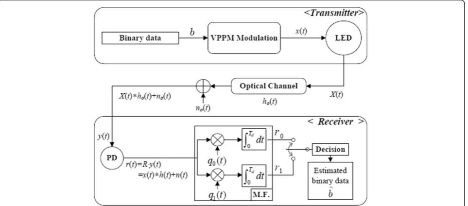
2. System description
Figure 2 shows the proposed structure of the VLC system based on VPPM. When binary data b∈{0, 1} are transmitted, the VPPM modulated signal s(t) is gener-ated considering the target dimming level as follows:
* Correspondence:[email protected]
Department of Electronic Engineering, Yeungnam University, 214-1 Dae-dong, Gyeongsan-si, Gyeongsangbuk-do 712-749, Republic of Korea
s tð Þ ¼
ffiffiffiffiffiffiffiffiffiffiffiffi
Es⋅d
50 r
⋅φ0ð Þt ;for b¼0
ffiffiffiffiffiffiffiffiffiffiffiffi
Es⋅d
50 r
⋅φ1ð Þt ;for b¼1
; 8
> > < > >
: ð
1Þ
where Es is the symbol energy, d is the dimming level (0≤d≤100). φi(t)(i= 0, 1) is the basis function that
changed according to dimming level. Section 3 provides details of the basis function. After passing through a VPPM pulse-shaping filter, the transmitted signal has the following form:
x tð Þ ¼X
∞
i¼−∞
s tð−iTdÞ; ð2Þ
whereTdis the total time duration required to transmit
each data block, Td=Ts+Tg, where Ts is the symbol
duration and Tg is the guard time to avoid inter-symbol
interference caused by channel dispersion. The LED is driven by the current signal controlled byx(t). The LED emits the light signal X(t), which has the mean optical
power, Pt ¼T1∫Td
0 X tð Þdt. After passing through the
optical channel ho(t), the optical signal y(t) received is
given as follows:
y tð Þ ¼X tð Þ hoð Þ þt noð Þt ; ð3Þ
where ‘*’ denotes convolution and no(t) is the optical
noise source.
Subsequently, y(t) is converged to an electric signal through a photodiode (PD) to produce the signalr(t) as follows:
r tð Þ ¼R⋅y tð Þ
¼R X tð ð Þ hoð Þ þt noð Þt Þ
¼Hð Þ0 ⋅x tð Þ h tð Þ þn tð Þ;
ð4Þ
where Ris the PD conversion responsivity (A/W), H(0) means the path loss gain of the signal, h(t) denotes the electrical impulse response of the optical wireless channel, andn(t) is the electrical additive white Gaussian noise.
This paper adopts the diffuse channel model to under-stand the effects of the channel condition in an operating VPPM scheme. By examining previous studies in optical wireless channel models [5-7], we propose the multiple ex-ponential channel model given as
Figure 1Operating example of VPPM in case of 75% dimming level.
h tð Þ ¼X C
i¼0
Gi⋅exp −τi⋅ t−td;i
⋅u tð Þ; ð5Þ
whereCis the number of channel cluster,Giis the channel
gain of theith cluster,τiis the time constant of theith
clus-ter, andtd,iis the time delay of theith cluster.
The hard decision decoding at the receiver was considered. The receiver was also assumed to be synchronized precisely with the transmitter. Whenr(t) is received, the receiver will generate the received vector r= [r0,r1] through a matched filtering process
as follows:
r0¼∫Td
0 r tð Þ⋅q0ð Þt dt ð6Þ
r1¼∫Td
0 r tð Þ⋅q1ð Þt dt ð7Þ
where qi(t) =φi(t)∗h(t) (i= 0, 1) denotes the template
pulse dispersed by the channel.
Based on the maximum likelihood decision rule, the transmitted signal is detected as
^
b¼ arg maxj¼0;1rj ð8Þ
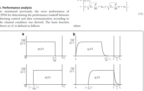
3. Performance analysis
As mentioned previously, the error performance of VPPM for determining the performance tradeoff between dimming control and data communication according to the channel condition was derived. The basis function shown in (1) is defined as follows:
φ0ð Þ ¼t
( ffiffiffiffiffiffiffiffiffiffi100
d⋅Ts
r
; 0≤t≤d⋅Ts
100 0 ; otherwise
φ1ð Þ ¼t
( ffiffiffiffiffiffiffiffiffiffi100
d⋅Ts
r
; 1− d
100
⋅Ts≤t≤Ts
0 ; otherwise
; ð9Þ
where φi(t) and the corresponding template pulse qi(t)
are normalized to have a unit energy as ∫Ts
0 φi2ð Þt dt¼1
and ∫Ts
0 qi2ð Þt dt¼1 . Figure 3 shows the signaling
struc-ture of the basis function, φi(t), and the template pulse,
qi(t).
If it is assumed that data bit‘0’ is transmitted (b = 0), the signal received is rewritten as follows:
r tð Þ ¼γ⋅
ffiffiffiffiffiffiffiffiffiffiffiffi
Es⋅d
50 r
⋅q0ð Þ þt n tð Þ; ð10Þ
whereγ=R⋅H(0) means the scaling coefficient that con-tains the effect of the channel path loss gain and PD responsivity.
After matched filtering, the received vector r can be obtained as follows:
r¼½r0;r1
¼ γ⋅ ffiffiffiffiffiffiffiffiffiffiffiffi
Es⋅d
50 r
þn0;γ⋅
ffiffiffiffiffiffiffiffiffiffiffiffi
Es⋅ d
50 r
⋅αþn1
" #
;
ð11Þ
where
r0¼∫Td
0 r tð Þ⋅q0ð Þt dt
¼∫Td
0 γ⋅
ffiffiffiffiffiffiffiffiffiffiffiffi
Es⋅ d
50 r
⋅q02ð Þt dtþ∫Td
0 q0ð Þt ⋅n tð Þdt
¼γ⋅
ffiffiffiffiffiffiffiffiffiffiffiffi
Es⋅ d
50 r
þn0
ð12Þ
r1¼∫Td
0 r tð Þ⋅q1ð Þt dt
¼∫Td
0 γ⋅
ffiffiffiffiffiffiffiffiffiffiffiffi
Es⋅ d
50 r
⋅q0⋅q1ð Þt dtþ∫Td
0 q1ð Þt ⋅n tð Þdt
¼γ⋅ ffiffiffiffiffiffiffiffiffiffiffiffi
Es⋅ d
50 r
⋅αþn1
ð13Þ
where n0,n1 becomes Gaussian random noise with a
zero mean and variance N0/2. α represents the
correl-ation factor, which is defined as follows:
α¼∫Td
0 q0ð Þt ⋅q1ð Þt dt: ð14Þ
In addition, two noise terms (n0,n1) were also
corre-lated due to the correlation factorαas shown below:
E n0f ⋅n1g ¼∫Td
0 ∫T0dE n tf ð Þnð Þτ g⋅q0ð Þt ⋅q1ð Þτ dtdτ
¼N0 2 ⋅∫
Td
0 q0ð Þt ⋅q1ð Þτ dt¼ N0
2 ⋅α:
ð15Þ
Accordingly, it affects the performance of VPPM. Therefore, it is important to consider this correlation factor carefully when operating VPPM.
To evaluate the error performance analytically, the new random variable is defined asz=r0−r1. The
condi-tional mean and variance ofzare given as follows:
Ezjb¼0¼E r0f g−E r1f g
¼γ⋅
ffiffiffiffiffiffiffiffiffiffiffiffi
Es⋅ d
50 r
⋅ð1−αÞ ð16Þ
Varz b ¼0g ¼E n0ð −n1Þ2¼N0⋅ð1−αÞ: ð17Þ
Noting that the position with a maximum value among rj 1j¼0is determined to be the transmitted signal
in the ML scheme, the error probability can be expressed as [8]
Pejb¼0¼P z<0 b¼0Þ ¼∫0−∞pzðz bj ¼0Þdz;
ð18Þ
where Table 1 Channel parameters for simulations
Channel Parameter Value
LOS h(t) =δ(t)
Diffuse Number of clusters 1
Channel gain (Gi) 1
Time delaytd,i 20 ns
Time constant 2.3 × 10⁸
pzðzjb¼0Þ ¼ ffiffiffiffiffiffiffiffiffiffiffiffiffiffiffiffiffiffiffiffiffiffiffi1 2πN0ð1−αÞ
p exp − z−γ⋅
ffiffiffiffiffiffiffiffiffiffiffi Es⋅50d q
⋅ð1−αÞ
2
2N0ð1−αÞ 2
6 4
3 7 5:
ð19Þ
Using (18) and (19), the error probability, b = 0, can be derived as follows:
Pejb¼0¼
1
2erfc γ⋅ ffiffiffiffiffiffiffiffiffi
Es
2N0
r ⋅
ffiffiffiffiffiffiffiffiffiffiffiffiffiffiffiffi
d⋅ð1−αÞ
50
r !
; ð20Þ
where erfc xð Þ ¼ 2ffiffiffi π
p ∫∞
xexp −t2
dt. Similarly, the error probability,Pe|b= 1, can be derived as follows:
erfc xð Þ ¼p2ffiffiffiπ
Z ∞
x
exp−t2dt ð21Þ
Because a priori probability of b = 0 and b = 1 is equal to 1/2, the error probability of VPPM can be expressed as
Pe¼P bf ¼0g⋅Pejb¼0þP bf ¼1g⋅Pejb¼1
¼1
2erfc γ⋅ ffiffiffiffiffiffiffiffiffi
Es 2N0 r
⋅
ffiffiffiffiffiffiffiffiffiffiffiffiffiffiffiffi d⋅ð1−αÞ
50
r !
: ð22Þ
4. Simulation result
The VPPM scheme was described, and its error perform-ance was analyzed. This paper presents the analytical and simulated results to test the validity of the analysis and the relationship between the dimming and commu-nication performance in the line-of-sight (LOS) and dif-fuse channel cases.
By referring to references [5-7], the channel parame-ters for the simulation are listed in Table 1.
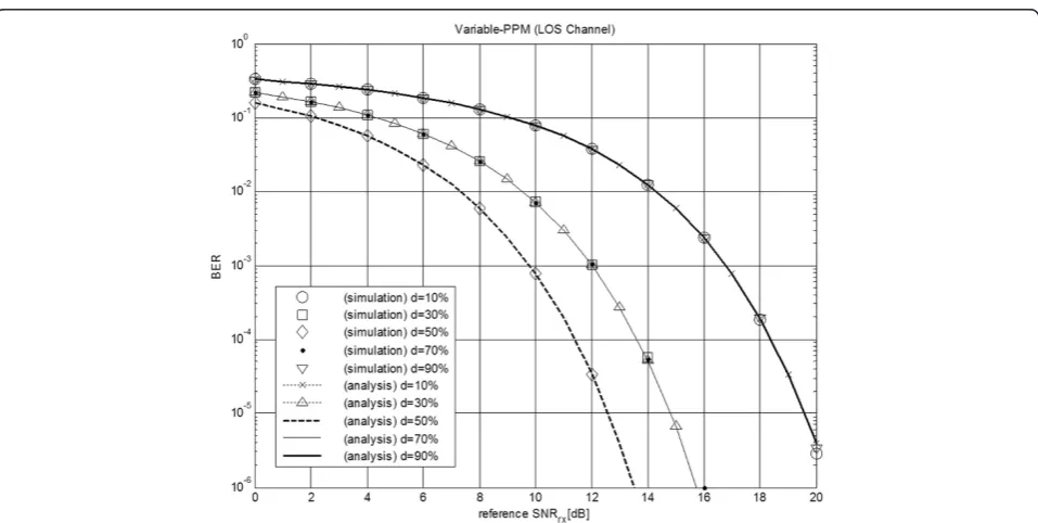
Figure 4 shows the analytical and simulated bit error rate (BER) performance according to the reference re-ceived signal-to-noise ratio (SNRrx) by changing the
dimming levels in the LOS channel case. The reference SNRrxdenotes the amount of noise power by setting the
signal power with a 50% dimming level as the reference signal power. Therefore, the actual SNRrx will be
changed according to the dimming ratio. The figure shows that the analytical curves are well matched with the simulation curves. Therefore, the analytical results
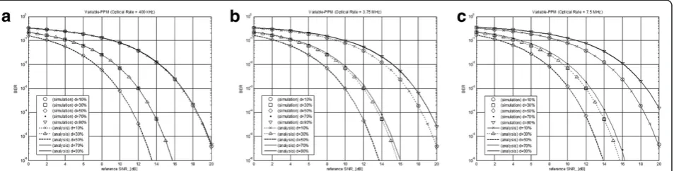
Figure 5The BER performance of VPPM in a diffuse channel case according to optical rate of LED.(a) 400 kHz, (b) 3.75 MHz, and (c) 7.5 MHz.
provide a good estimation of the performance when the system parameters have been selected. VPPM showed the best performance at the 50% dimming level with the BER degrading symmetrically as the dimming level strays from 50%. A dimming level less than 50% is due to less allocated signal energy. When the dimming level is greater than 50%, the increasing correlation factor degrades the performance faster than the increase in allocated signal energy. Therefore, the dimming levels in VPPM strongly affect the communication performance.
Figure 5 shows the analytical and simulated BER per-formance in the diffuse channel case. The optical rate of the LED according to the IEEE standard was changed to examine the effects of channel dispersion on the com-munication performance [4]. Figure 5a shows the result when the optical rate is 400 kHz. A similar result was obtained in the LOS case. On the other hand, the BER performance of the optical rate (3.75 and 7.5 MHz) in Figure 5b,c is degraded when the dimming level is greater than 50%. This is because the relative length of the channel delay spread is becoming longer than the symbol duration (Ts) as the optical rate is increasing.
This causes a larger correlation factor, which degrades the BER performance.
Figure 6 shows the relationship between VPPM and the BER performance according to (1) the distance be-tween TX and RX, (2) the dimming ratio, and (3) the op-tical rate of a LED under the VLC scenario in reference [1]. Because the VLC performance based on VPPM af-fects the design of LED illumination infrastructure, it will be meaningful to express communication perform-ance based on the distperform-ance, optical rate, and dimming ratio under a given VLC scenario. Therefore, the actual SNRrxwill be determined as a function of the distance,
dimming level, optical rate, and environment settings. Figure 6a shows that the distance between TX and RX should be in the range of approximately 2.5 to 3.8 m to achieve a 10−4BER and 10% to 90% dimming flexibility. In the case of Figure 6b,c, the distance between TX and RX becomes shorter to obtain the same performance (approximately 1.4 ~ 2.2 m at a 3.75-MHz optical rate and 1.5 ~ 1.8 m at a 7.5-MHz optical rate). This is be-cause the noise bandwidth and correlation factor due to a channel dispersion increase with increasing optical rate.
5. Conclusion
The error performance of VPPM was analyzed, and the results were confirmed by a simulation under LOS and diffuse channel conditions. An examination of the rela-tionships among the BER curve, dimming level, and op-tical rate according to the reference SNRrx revealed
tradeoffs between the dimming flexibility and communi-cation performance according to the channel condition
if the VPPM scheme for VLC is considered. Care should be taken when designing LED illumination infrastructure with a VLC support based on VPPM because the SNRrx
in a VLC is related to the LED luminance distribution.
Competing interests
The authors declare that they have no competing interests.
Acknowledgments
This research was supported by the Basic Science Research Program through the National Research Foundation of Korea (NRF), funded by the Ministry of Education, Science and Technology (No. 2010-0021118).
Received: 26 March 2012 Accepted: 8 May 2013 Published: 24 May 2013
References
1. T Komine, M Nakagawa, Fundamental analysis for visible-light
communication system using LED lights. IEEE Trans On Consumer Electron
50(1), 100–107 (2004)
2. J Grubor, S Randel, K-D Langer, JW Walewski, Broadband information broadcasting using LED-based interior lighting. J Lightw Technol26(24), 3883–3892 (2008)
3. T Komine, JH Lee, S Haruyama, M Nakagawa, Adaptive equalization system for visible light wireless communication utilizing multiple white LED lighting equipment. IEEE Trans Wireless Comm8(6), 2892–2900 (2009) 4. IEEE Std 802.15.7,IEEE Standard for Local and Metropolitan Area
Networks-Part 15.7, Short-Range Wireless Optical Communication Using Visible Light (IEEE, Piscataway, 2011)
5. JB Carruthers, P Kannan, Iterative site-based modeling for wireless infrared channels. IEEE Trans Antennas and Propagation50(5), 759–765 (2002) 6. JR Barry, JM Kahn, WJ Krause, EA Lee, DG Messerschmitt, Simulation of
multipath impulse response for indoor wireless optical channels. IEEE J Sel Area Comm11(3), 367–379 (1993)
7. X Zhang, K Cui, M Yao, H Zhang, Z Xu, Experimental characterization of indoor visible light communication channels, in8th International Symposium on Communication Systems, Networks & Digital Signal Processing (CSNDSP) (Poznan, 2012). 8–20 July 2012, pp. 1–5
8. JG Proakis, M Salehi,Digital Communication, 4th edn. (McGraw-Hill, New York, 2006)
doi:10.1186/1687-1499-2013-134
Cite this article as:Yoo and Jung:Modeling and analysis of variable PPM for visible light communications.EURASIP Journal on Wireless Communications and Networking20132013:134.
Submit your manuscript to a
journal and benefi t from:
7Convenient online submission 7Rigorous peer review
7Immediate publication on acceptance 7Open access: articles freely available online 7High visibility within the fi eld
7Retaining the copyright to your article