© 2015, IRJET.NET- All Rights Reserved
Page 1723
Performance of Thermal Power Plant on System Based
Mr. Manjeet B Shende
1, Prof. N. N. Shinde
2*, Prof. S. B. Desai
3*, Prof. M.M. Wagh
4*1 2 4
Energy Technology, Dept. of Technology, Shivaji University, Kolhapur,India.
3YCSRD, Shivaji University, Kolhapur, India.
---***---Abstract -
The steam is used for rotate the turbinein thermal power plant. In India power generation is largely depends upon thermal power plant which having share of 71% of total generation. In view of energy conservation and possibility of scarcity of fuel there is need to check the performance of thermal power plant.
The Energy audit generally carried out by equipment and devices based energy efficiency improvements by way of testing in operation and on field i.e. load variation. The system based energy audit would indicate the practice system efficiencies and its integration for whole power plant performance such approaches have not be considered so far and must be tried. The actual performance of thermal power vary due to quality of used fuel, excess air control, viscosity of working fluid, turbulence, environmental impacts.
An effort is made in this work for developing methodology of energy audit in thermal power plant on system based. The paper shows all the performance equation of component involves in the thermal power plant according to the system base.
Key Words
:Energy Audit, Thermal Power Plant,
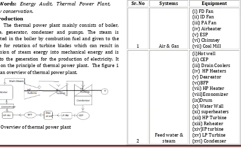
shows an overview of thermal power plant.Fig -1: Overview of thermal power plant
For conservation of fuel it is required to carry out energy audit of thermal power plant otherwise scarcity of fuel in future occurs. Pains taking task work with rMany people’s had done the works on performance of thermal power plant according to the equipment based. But system based work hadn’t found for auditing the thermal power plant. There is potential of energy conservation on the basis of system based audit. The thermal power plant mainly consists of following systems
1) Air and flue gas system
2) Feed water and steam system
3) Cooling water system
4) Fuel and ash handling system
© 2015, IRJET.NET- All Rights Reserved
Page 1724
3 Cooling Water
(i) Cooling tower (ii) CWP
4 Fuel & Ash
(i) Conveyer Belt (ii)Feeders
(iii) Crusher (v) Ash Water Pump
(vi) Ash Disposal Pump
5
Electrical Systems
(i) Transformer
(ii)Motors
Table -1: Thermal Power Plant System
II) Methodology
In view of EnmS 50001:2011, the study of thermal power plant system is done. According to study list of various performances equation of equipment according to system is carried out.
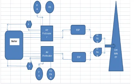
1) Performance of Air and flue gas system.
Air is required for combustion purpose in thermal power plant and due to combustion of fuel, flue gas is formed which is used for heating purpose. The equipment are involves in the system are shown in figure 2.
Fig -2: Air and Flue gas system
The performance of flue gas system can be calculated as follows.
Ƞ(%) =
a) Performance efficiency of FD, PA, ID fan can be calculated as follows
b) Performance of APH can be calculated as follows.
Where,
Q= Heat Transfer in kcal/hr
A= Heat Transfer surface area in m2
LMTD= Log mean Temp difference in ◦ C
U= Overall heat transfer coefficient
kcal/hr/m2/◦C
LMTD can be calculated as follows
For Counter Flow
For Parallel Flow
Where,
Ti = Inlet temperature of Hot air T0= Outlet Temperature of hot air ti= Inlet Temperature of cold air to= Outlet Temperature of cold air
c) Performance of ESP
Performance of precipitator = 1 – [e](-Aw/V)
Migration Velocity (w) =
Where,
A= Effective Precipitating collecting electrode area
V= Gas Flow through the precipitator
r = Radius of the particle
E1= Strength of particle charging field (volts)
E2= Strength of particle collecting field (volts)
μ = Viscosity of frictional coefficient of the gas
d) Performance of chimney
For the performance purpose of chimney the efficiency
can be carried out as follows
© 2015, IRJET.NET- All Rights Reserved
Page 1725
Where,
H= Height
J = In SI unit J is equal to 1
ma= mass of air supplied per kg of fuel
ma+1= mass of chimney gases
Tg = average absolute temperature of chimney gases
Ta = absolute temperature at atmosphere
T1= Absolute temperature of flue gases leaving the
chimney to create draught
T2 = Absolute temperature of flue gases leaving the
chimney in case of artificial draught
e) Performance of coal mill
In the performance of coal mill air fuel ratio and Specific
energy consumption of coal can be check. It can be
calculated as follows
Air fuel Ratio=
SEC of coal (kWhr/T) =
2) Performance of Feed water and steam system
The feed water is required for generating the steam in boiler and is given to the turbine. After the work done in turbine steam is dumped in condenser and conversion of steam to water takes place. The equipment involves in this system is shown in figure no. 3
Fig -3: Feed Water and steam system
The performance of feed water and steam system can be calculated as follows
η (%)=
a) Performance of CEP and BFP
×100
Where,
Where,
Q= mass flow rate (m3/sec) ρ= Density of fluid (kg/m3)
g= acceleration due to gravity (m/s2) Hd-Hs= Total Head in meters
b) Performance of HP & LP heaters
For the performance purpose of LP & HP heaters
effectiveness can be carried out
Where,
Ti = Inlet temperature of condensate To= Outlet Temperature of condensate ti= Inlet Temperature of extracted steam to= Outlet Temperature of extracted steam
c) Performance of Boiler
The performance of boiler can be calculated as by direct method and indirect method
i. Direct Method
Boiler efficiency (Ƞ) =
Where,
hg– Enthalpy of saturated steam in kCal/kg of steam
hf – Enthalpy of feed water in kCal/kg of water
Q – Quantity of steam generated per hour (Q) in kg/hr.
q– Quantity of fuel used per hour (q) in kg/hr
GCV – gross calorific value of the fuel in kCal/kg of fuel
ii. Indirect Method
In indirect method, efficiency is the difference between the losses and energy input
The following losses are applicable to coal fired Boiler
L1. Loss due to dry flue gas (sensible heat)
L2. Loss due to hydrogen in fuel (H2)
L3. Loss due to moisture in fuel
© 2015, IRJET.NET- All Rights Reserved
Page 1726
L5. Loss due to carbon monoxide (CO)
L6. Loss due to surface radiation, convection and other
unaccounted
L7. Unburnt losses in fly ash (Carbon)
L8. Unburnt losses in bottom ash (Carbon)
Boiler Efficiency by indirect method = 100 - (L1 + L2 + L3
+ L4 + L5 + L6 + L7 + L8)
Calculation procedure For Indirect Method
Theoretical (stoichiometric) air fuel ratio and excess air
supplied are to be determined first for computing the
boiler losses
a. Theoretical air required for
combustion=[(11.6×C)+{34.8×(H2 –
O2/8)}+(4.35×S)]/100
Where C, H2 O2 and S are the percentage of carbon, hydrogen, oxygen and sulphur present in fuel
b. % Excess Air Supplied (EA) =
c. Actual mass of air supplied /kg of fuel (AAS)= {1+EA/100}×theoretical air
The various losses associated with the operation of a
boiler are discussed below with
Required formula
1. Heat loss due to dry flue gas
Where,
L1 = % Heat loss due to dry flue gas
m = Mass of dry flue gas in kg/kg of fuel
= Combustion products from fuel: CO2 + SO2 +
Nitrogen in fuel +Nitrogen in the actual mass of air
supplied + O2 in flue gas.
(H2O/Water vapour in the flue gas should not be
considered)
Cp = Specific heat of flue gas in kCal/kg°C
Tf = Flue gas temperature in °C
Ta = Ambient temperature in °C
2. Heat loss due to evaporation of water formed due to
H2 in fuel (%)
Where
L2=Heat loss due to evaporation of water formed due to
H2 in fuel
H2 = kg of hydrogen present in fuel on 1 kg basis
Cp = Specific heat of superheated steam in
kCal/kg°C
Tf = Flue gas temperature in °C
Ta = Ambient temperature in °C
584=Latent heat corresponding to partial pressure of
water vapour
3. Heat loss due to moisture present in fuel
Where
L3 = Heat Loss due to moisture present in fuel
M = kg moisture in fuel on 1 kg basis
Cp = Specific heat of superheated steam in kCal/kg°C
Tf = Flue gas temperature in °C
Ta = Ambient temperature in °C
584 =Latent heat corresponding to partial pressure of
water vapour
4. Heat loss due to moisture present in air
Where
L4=Heat loss due to moisture present in air
AAS = Actual mass of air supplied per kg of fuel
Humidity factor = kg of water/kg of dry air
Cp = Specific heat of superheated steam in kCal/kg°C
Tf = Flue gas temperature in °C
Ta = Ambient temperature in °C (dry bulb)
© 2015, IRJET.NET- All Rights Reserved
Page 1727
Where,
L5 = % Heat loss due to partial conversion of C to CO
CO = Volume of CO in flue gas leaving economizer (%)
CO2 = Actual Volume of CO2 in flue gas (%)
C = Carbon content kg / kg of fuel
6. Heat loss due to radiation and convection:
0.548 x [ (Ts / 55.55)4- (Ta / 55.55)4] + 1.957 x (Ts -
Ta)1.25 x sq.rt of
[(196.85 Vm + 68.9) / 68.9]
Where
L6 = Radiation loss in W/m2
Vm = Wind velocity in m/s
Ts = Surface temperature (K)
Ta = Ambient temperature (K)
7. Heat loss due to unburnt in fly ash :
8. Heat Loss due to unburnt in bottom ash
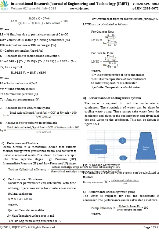
d) Performance of Turbine
Steam turbine is a mechanical device that extracts thermal energy from pressurized steam, and converts to useful mechanical work. The steam turbines are split into three separate stages, High Pressure (HP), Intermediate Pressure (IP) and Low Pressure (LP) stage.
e) Performance of Condenser
Condenser performance can deteriorate with time,
offdesign operations and other interferences such as
fouling, scaling etc
Where,
Q= Heat Transfer in kcal/hr
A= Heat Transfer surface area in m2
LMTD= Log mean Temp difference in ◦ C
U= Overall heat transfer coefficient kcal/hr/m2/◦C
LMTD can be calculated as follows
For Counter Flow
For Parallel Flow
Where,
Ti = Inlet temperature of Hot condensate To= Outlet Temperature of hot condensate ti= Inlet Temperature of cold water to= Outlet Temperature of cold water
3) Performance of Cooling water system
The water is required for cool the condensate in condenser. The circulation of water can be done by cooling water pump. These pumps take water from the condenser and given to the cooling tower and given back the cold water to the condenser. This can be shown in figure no. 4
Fig -4: Cooling water system
Performance of cooling water system can be calculated as follows
η cooling water system (%)=
a) Performance of cooling water pump
The water is required for cool the condensate in condenser. The performance can be calculated as follows.
×100
© 2015, IRJET.NET- All Rights Reserved
Page 1728
Where,
Q= mass flow rate (m3/sec) ρ= Density of fluid (kg/m3)
g= acceleration due to gravity (m/s2) Hd-Hs= Total Head in meters
b) Performance of Cooling Tower
The cooling tower efficiency can be expressed as
Ƞ = (ti - to) ×100 / (ti - twb)
Where,
Ƞ
= cooling tower efficiency (%)t
i= inlet temperature of water to the tower (oC)t
o= outlet temperature of water from the tower (oC)t
wb= wet bulb temperature of air (oC) 4) Fuel and ash systema) Fuel handling system
The fuel handling plant mainly consists of equipment like crusher, feeder, and conveyor. So for the purpose of performance of this equipment motors performance can be carried out as follows
Efficiency of motor is given by
Where,
Pout – Output power of the motor Ploss – Losses occurring in motor Pin – Input power of the motor Motor Loading can be calculated as
b) Ash handling system
In ash handling plant mainly consist of pumps. So the
performance of pump can be carried out as follows.
×100
Where,
Where,
Q= mass flow rate (m3/sec) ρ= Density of fluid (kg/m3)
g= acceleration due to gravity (m/s2) Hd-Hs= Total Head in meters
5) Performance of Compressed air system
In thermal power plant Compress Air is required for Instrumentation and service. The performance of compressor can be calculated as follows.
i.
Where,
K: Flow coefficient – as per IS
d: Nozzle diameter M
T1: Absolute inlet temperature °K
P1: Absolute inlet pressure kg/cm2
P3: Absolute Pressure before nozzle kg/cm2
T3: Absolute temperature before nozzle °K
Ra: Gas constant for air 287.1 J/kg k
P3–P4: Differential pressure across the nozzle kg/cm2
ii.
Where,
P1 = Absolute intake pressure kg/ cm2
Qf = Free air delivered m3/hr.
r = Pressure ratio P2/P1
iii.
iv.
Where,
D = Cylinder bore, metre
L = Cylinder stroke, metre
S = Compressor speed rpm
© 2015, IRJET.NET- All Rights Reserved
Page 1729
2 for double acting cylinders
n = No. of cylinders
6) Performance of Lightening system
Lighting is provided in Thermal Power plant for providing comfortable working environment. The performance can be calculated as follows.
Calculate the Room Index
Where,
L = length of interior;
W = width of interior;
Hm = the mounting height
7) Insulation system
Insulation is given to the heating surfaces of the thermal power plant.
Heat loss from a surface is expressed as
Where,
h = Heat transfer coefficient, W/m2–K
H = Heat loss, Watts
Ta = Average ambient temperature, ºC
Ts = Desired/actual insulation surface temperature, ºC
Th = Hot surface temperature
III) Conclusion
This works given an idea for auditing the thermal power
plant. The performance of the thermal power plant can
be check on the basis of system based which brought
several options that result in reduction of energy
conservation.
REFERENCES
1. Vikas Duhan, Jitender Singh “Energy Audit of Rajiv
Gandhi Thermal Power Plant Hisar” JRPS
International Journal for Research Publication & Seminar Vol 05 Issue 02 March -July 2014
2. Ch.Kiran Kumar, G.Srinivasa Rao “Performance
Analysis from the Energy Audit of A Thermal Power
Plant,”IJETT - Volume4 Issue6- June 2013
3. A G Vinchurkar, Dr R R Lakhe, Dr R L Shrivastava,
“Energy management and optimizing energy in
thermal power station,” IJAERD, Volume 1,Issue 7,July
2014
4. Jinendra K Gugaliya,*, Naveen Bhutani, and Mohan S Kumar, “Energy Assessment for Power Plants” Proceedings of the 6th International Conference on Process Systems Engineering (PSE ASIA), 25 - 27 June 2013, Kuala Lumpur
5. Ms.Shradha Chandrakant Deshmukh, Ms.Varsha Arjun
Patil ,“Energy conservation and Audit in TPS”
International Journal of Scientific and Research
Publications, Volume 3, Issue 8, August 2013.
6. Namdeo D. Adate, R. N. Awale, “energy conservation through energy efficient Technologies at thermal power plant,” International Journal of Power System Operation and Energy Management ISSN (PRINT): 2231 – 4407, Volume-2, Issue-3,4. 2013
7. K.R. Shanmugam, Praveen Kulshreshtha, “Efficiency
analysis of coal-based thermal power generation in India during post-reform era” Int. J. Global Energy Issues, Vol. 23, No. 1, 2005
8. S.C.Arora and S. Domkundwar “A Course in Power
Plant Engineering”. Dhanphat Rai & Co. (P) Ltd. Educational & Technical Publication
9. Energy Efficiency: A Worldwide Review” World
Energy Council, Energy Efficiency Policies and Indicators, published on July 2004
10. Mr. Santosh Mahadeo Mestry, “ Technical paper on major energy saving potential in thermal power plant & effective implementation of EC Act 2001 in Power Sector (Issue#28)” Reliance energy Ltd
11. Bureau of energy efficiency Energy audit Guide books
1, 2, 3.4 published in 2005.
Book1: General aspects of energy management and energy
audit
Book2: Energy efficiency in Thermal utilities