ANALYSIS AND COMPARISON OF DIAGRID AND CONVENTIONAL
STRUCTURAL SYSTEM
Raghunath .D. Deshpande
1, Sadanand M. Patil
2, Subramanya Ratan
31
Assistant Professor, Dept of Civil Engineering, Gogte Institute of Technology Belagavi, Karnataka, India
2
Assistant Professor, Dept of Civil Engineering, Gogte Institute of Technology Belagavi, Karnataka, India
3
Post Graduate Student in Structural Engineering, Dept of Civil Engineering, Gogte Institute of Technology Belagavi,
Karnataka, India
Abstract
Advances in materials, construction technology, analytical methods and structural systems for analysis and design initiated development of tall Structures. Structural design for tall structures is governed by horizontal forces due to earthquake and wind load. Lateral load is resisted by exterior structural system or interior structural system. Usually braced frame, shear wall core and their combination with frames are interior system, where lateral force is resisted by centrally located elements.Diagrid structural systemis adopted in tall Structures due to its flexibility in floor area and structural. Diagrid consists of inclined columns on the façade. Due to inclined columns lateral loads are resisted by axial action of the diagonal compared to bending of vertical columns in framed tube structure. Diagrid structures generally do not require core because lateral shear can be carried by the diagonals on the periphery of building. Analysis and design of 60 storey diagrid steel building is presented. A regular floor plan of 24 m × 24 m size is considered. ETABS software is used for modeling and analysis of structural members. All structural members are designed as per IS 800:2007 considering all load combinations. Dynamic along wind and across wind are considered for analysis and design of the structure. Later both Conventional and Diagrid Structural Systems are compared.
Key Words: Diagrid, Conventional Structural System, E-TABS, Optimum Angle, Diagonals, Tracking Nodes, Axial
force.
---***---1. INTRODUCTION
1.1 General
Tall buildings have developed in response to the requirements arising from the continuing increase in world population. In recent times, the demand for these buildings is increased enormously, especially driven by environmental considerations. In the resource scarce era, expanding a building vertically to develop a denser city is more energy efficient because the energy consumed for transferring electricity can be minimized, while the land used for building will be reduced and thus saving more green areas. Therefore, through this project an attempt has been made to arrive at a structural pattern which is superior as compared to conventional structural systems.
In the tall structures, structural pattern can be manipulated to optimize the performance. By arranging the structural members in a particular pattern, efficient structure can be produced, whereas the economy can be increased by grouping structural member dimensions according to their arrangement. Moreover, by a high performance pattern, member sizes can be minimized and thus opening areas can
be maximized. In terms of expressiveness, the use of a certain pattern in a tall building can produce a unique architectural appearance. Therefore the present trend has been for more buildings to employ non routine structural patterns. With this project we want to present non-routine structural patterns as an alternative to replace the orthogonal pattern.
2. DIAGRID
2.1 What is Diagrid?
“DIAGRID (a portmanteau of diagonal grid) is a design for constructing tall buildings with steel that creates triangular structures with diagonal support beams.” It is triangulated beam system which may be curved or straight, and horizontal beams that make structural system for high rise structure. The difference in exterior-braced conventional frame structural pattern and the diagrid structural pattern is that these buildings do not use conventional vertical columns.
2.2 Principle of Diagrid
upgrades each basic component. Ordinarily, segments are utilized to convey vertical burdens, and diagonals give steadiness and imperviousness to substantial strengths, for example, wind and seismic burdens. Yet, Rahimian [structural architect for the Hearst Tower] says that diagonals and props "need" to convey vertical burden and the segments need to convey sidelong load under perfect presumptions in an average tall structure. In a DIAGRID auxiliary framework the two capacities are hitched, he says. 'The sections, diagonals and bracings all are one.'- "Milestone Reinvented" by Brian Fortner.
3. METHODOLOGY
3.1 Gravitational and Lateral Load Calculations
The Gravity force includes the Dead load and Live load. The live load on the floor will remain constant across all the structural systems considered. Dynamic Analysis for wind force calculations will be in accordance with IS 875 (Part 3) to discern the Lateral load.
3.2 Geometrical Specifications
Based on the analysis and design from ETABS the most economical section of the members is obtained.
3.3 Common Building Parameters
Table.3.1: Common Building Parameters
3.4 PLAN
Fig.3.1: Plan
3.5 Load Combinations
Table.3.2: Load Combinations
Sl.No Combination Purpose 1 1.5x(Dead Load)+1.5x(Live
The load combinations applicable for the design perimeter structure are; and analysis of the perimeter structure is carried out for load case (a) by taking the input from floor frame and wind load analysis. The sections obtained are then checked by considering the other load case.
4. CALCULATION OF DESIGN WIND FORCES
4.1 Wind Data
The height to least lateral dimension is more than 5, (180/24) Dynamic analysis is needed.
(IS875 (Part 3) - 1987, Sec 7.1) 1. Basic Wind Speed, Vb = 33m/s
2. Terrain category = 2 “Analysis and Comparison of Diagrid and Conventional Structural System”
4.2 Design Factors
Core wall dimension 12mx12mNo of storeys 60 Core wall thickness 250mm
= 33 x k2 m/s
(IS875 (Part 3) - 1987, Sec 5.3)
4.4 Design Wind Pressure (Pz)
Pz = 0.6 x (Vz)²
(Table-33, IS875 (Part 3) – 1987)
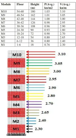
4.5 Wind Loads
The design wind loads are applied as ‘Floor loads” along the x-axis.
Table.4.1: Wind Pressure For Various Modules
Module Floor Height
(m)
P(Avg.) kn/m2
V(Avg.) kn/m
M10 54-60 180 1.03 3.10 M9 48-54 162 1.01 3.05 M8 42-48 144 1.00 3.00 M7 36-42 126 0.98 2.95 M6 30-36 108 0.96 2.90 M5 24-30 90 0.93 2.80 M4 18-24 72 0.90 2.70 M3 12-18 54 0.88 2.65 M2 6-12 36 0.80 2.40 M1 1-6 18 0.76 2.30
Fig 4.1 Wind Pressure For Various Modules
5. TRACKING NODES
In the module, a node which is having maximum deflection is defined as “Tracking Node”. Tracking nodes are must in order to compare actual deflection with theoretically determined limiting deflection. The actual deflection values of the tracking nodes must be less than the theoretical deflection values. Tracking nodes are placed at each module there by facilitating deflection check at particular intervals.
Fig 5.1 Tracking Nodes
6. CONVENTIONAL STRUCTURAL SYSTEM
6.1DESIGN OF PERIMETER STRUCTURE
6.1.1 Stiffness-Based Design
For tall structures with large aspect ratio, stiffness constraint will dominate the design. According to IS875-Part 3, horizontal displacement at top story should be limited to less than H/500 (where ‘H’ is the height of the structure).
6.1.2
Structural Details
Floor to floor spacing – 3m
Column to column spacing – 6m
In tall steel structure, the story height is kept quite large because the beam will be having large depth. Keeping this in hindsight floor height of 3m is provided. To reduce the complexity in assigning the force on the computer model and hence simplifying the structural analysis of the building, column spacing of 6m is provided. ‘Strong’ bending direction of the column is aligned along the face of the structure.
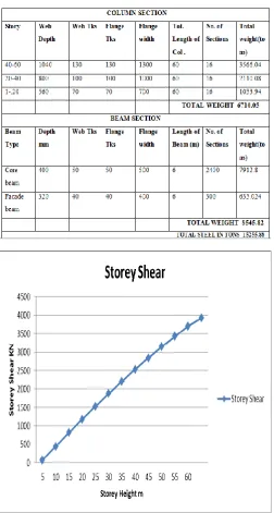
6.1.3 Design Section
Table 6.1 Total Steel Usage For Conventional Structural System
Fig.6.1: Graph showing Storey Shear at various floors.
Fig.6.2: Graph showing Deflection at various floors.
7. DESIGN OF DIAGRID
7.1 DESIGN OF PERIMETER STRUCTURE
7.1.1
Structural Details
Storey height – 4m
Steel sections – Circular Hollow Sections (CHS)
Diagonal angle – 72o (1-36 floors) 56o (36-60 floors)
Circular Hollow Sections (CHS) are adopted, because of their high efficiency relative to other sections.
Design Sections
Table.7.1: Total Steel Usage For Diagrid Structural System
Fig.7.1: Graph showing Deflection at various floors.
Fig.7.2: Graph showing Storey Shear at various floors.
PERFORMANCE COMPARISON
8.1 DIAGRID vs. CONVENTIONAL BUILDING
Fig.8.2: Comparison of steel usage of both structural frames
Table.8.1: Performance comparison between conventional and diagrid structure
Compared to Conventional Structure, Diagrid Structure has,
More opening area performance evaluation, such as, efficiency, expressiveness and sustainability.
Structure has comparatively less deflection.
Structural weight is reduced to greater extent.
Due to this structure has more resistance to lateral forces
Cost effective and Eco-friendly.
Diagrid uses 11247 tonnes of steel which is 28% less compared to the conventional orthogonal building which uses 15255 tonnes.
10. REFERENCES
[1]. Moon, K., Connor, J. J. and Fernandez, J. E. (2007). Diagrid Structural Systems for Tall Buildings: Characteristics and Methodology for Preliminary Design.” The Structural Design of Tall and Special Buildings (Vol. 16)”.
[2]. Moon, K. S. (2008). “Material Saving Design Strategies
for Tall Buildings”. CTBUH 8th World Congress.
[3].Smith, B.S., & Coull, A. (1991). “Tall Building Structures Analysis and Design”. New York: John Wiley & Sons, Inc.
[4]. Taranath, B. S. (1988). “Structural Analysis and Design of Tall Buildings”. New York: McGraw-Hill Book
[7]. Khajuria, A. (2008). “Estimation of Wind Loads in Tall Buildings”. M.Tech thesis submitted to Thapar University, Patiala..
[8]. . “Explanatory Handbook on IS:875 (Part 3)” – 1987.
(2001). New Delhi: Bureau of Indian Standards.
BIOGRAPHIES
Raghunath .D. Deshpande (M.tech structural Engg.)
Assistant Professor, Civil Engineering Department, Gogte Institute of Technology Belagavi, Karnataka, India.
Sadanand M. Patil (M.tech structural Engg.)
Assistant Professor, Civil Engineering Department, Gogte Institute of Technology Belagavi, Karnataka, India.
Subramanya Ratan (M.Tech Scholar)