www.ijiset.com
49
Hybrid Manufacturing Machine
Hamoud, M.P
1
P
,Gaber, A.P
2
P
, Mohamed, A.P
3
P
, Essam, I.P
4
P
, Mohamed, I.P
5
P
, Mustafa, I.P
6
P
,Emad, M.P
7
P
, Atef, M.P
8
P
, and Hamdy, M.P
9
P
P
1
P
Assistant Professor, P 2 to 9
P
Students at Mechanical Eng. Dept, Faculty of Eng., Helwan University, Cairo, Egypt
Abstract-
Recently, the integration between the additive and subtractive manufacturing has drawn an attention of many industries to reduce the time and cost for development of new product in medical implants, in architecture and in freeform fabrication that cannot be manufacturing by other means. Based on this fact, the paper aims at design and built a hybrid machine which contains both functions of 3D printing (3DP) and Laser cutting/engraving in one machine in order to reduce the effort, the waste time, the maintenance cost, the working area and to maximize the utilization of planet layout. In the machine, the 3DP is based on the technology of the Fused Deposition Modeling (FDM), and the laser system is based of Gas laser (CO2) source.Keywords-
Hybrid Machine, 3D Printing, Laser engraving/cutting, FDM.I.
INTRODUCTIONAdditive manufacturing (AM) has drawn interest from fields ranging from aerospace to tissue engineering [1]. Because this technology is being increasingly used in many applications, the technology is also known by several other names like Rapid Manufacturing (RM), Rapid Prototyping (RP), Layered Manufacturing (LM), Digital Fabrication, 3D printing(3DP), Free Form Fabrication (FFF), Desktop Manufacturing, Direct CAD Manufacturing, and Computer Automated Manufacturing [2]. AM is a process where an initially conceptualized 3D CAD model is fabricated by adding successive layers of material on top of each other while eliminating the need for any process planning. AM processes are gaining popularity in several industries such as aerospace, health care, architecture, industrial design, automotive and consumer products due to the ease with which complex parts can be manufactured [3]. CO2 laser technology is one of the most effective micromachining tools for low-conductive and brittle materials such as ceramics and glasses [4]. Hybrid production/manufacturing means the combination of processes/machines in order to produce parts in a more efficient and productive way of material and geometry. Combining both subtractive and additive process on a single platform has significant advantages. However, this has several challenges such as control system integration and maintaining accuracy of alignment during the changeover process. This research attempts to assimilate both of theseprocesses and propose a new design of hybrid machine with the purpose of overcoming the drawbacks related with different control panel and misalignment issues [5]. In addition, 3DP is going to become a basic equipment at home in the future [6].
II.
MACHINE CONFIGURATIONwww.ijiset.com
50
use just two axes of motion (x and y-axis). Generally, the machine is consisting of two main systems [mechanical and control system] as shown in Fig.1. In addition, the machine contains the 3DP head and the laser head module.A. The Mechanical Components and The Design
The mechanical components of the machine consist of machine frame, motors, lead screws, nuts, flexible couplers, bearings, timing belt, pulley drives, belt clamps, guide wheels, extruder, laser module, and laser cutting bed.
Figure1. The machine configuration
1.
The Machine FrameThe frame is built up by 2040 V-Slot aluminum extrusions and assembled together by aluminum L-angles, bolts and nylon lock nuts as shown in the Fig.2.
Figure2. a. 2040 V-Slot
16T
Figure2. b. L-angles for
assembly
Figure2. The machine frame
2.
MotorsThe stepper motor used in the machine is Nema 17, which have 200 steps per revolution, and torque equal to 3.2 Kg.cm.
www.ijiset.com
51
Based on the following design calculations, the machine will consist of four lead screws with 700 mm length, 8 mm diameter, and 2 mm pitch: the lead screw material is stainless steel with yield strength of 290 Mpa, and modulus of elasticity (E) = 193Mpa, and safety of factor (s.f) equal to 1.8.For the 1st mode of failure “compression stress”:
For the 2nd mode of failure “buckling stress”:
4. Flexible Couplers
The machine uses four Aluminum flexible couplers 5*8 mm to connect the four motor shafts with the four lead screws as shown in the Fig. 3.
Figure 3. (5*8) mm Flexible Coupler
5. Timing Belt and Pulley Drives
www.ijiset.com
52
resistance, and various types of steel wire core to ensure it remains in good operating capacity in high load transmission as shown in the Fig.5.Figure 4. GT2 36 teeth
timing pulley
Figure 5. Polyurethane
timing belt with steel wire
core
6. Belt Clamps
The two ends of the belt tied together by the Aluminum belt clamp; which are attached to the moving part with bolt.
7.
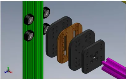
Guide WheelsThey are responsible for carrying any moving part in the machine, where it designed specifically to work as a guide of movement on the v-slots, that is why a specific guide wheel is designed; which consists of four V-Wheels and four assembly plates as shown in the Fig.6.
Figure 6. Guide Wheels
B. 3D Printer Head
www.ijiset.com
53
Figure 7. The cold top part
16TFigure 8. Hot end extruder
C. Laser Module
In the laser cutting process there are various types of laser that can be used. The type of laser module that used in the machine is co2 laser with 15-Watt, 450 nm laser focusing module which can cut 3 mm wood and engrave stainless steel and anode colored aluminum surface as shown in the Fig. 9.
Figure9. laser head
In addition to the laser cutting bed as it works as a support to the work piece to be cut. Laser cutting beds are available in many different sizes and designs, but the commonly used types are (Blade Worktable and Honeycomb Bed).
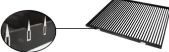
1. Blade Worktable
This table uses a blade system, which resemble numerous thin blades pointing up. The blade system minimizes contact with the products and allows adequate airflow underneath the object as shown in Fig.10.
www.ijiset.com
54
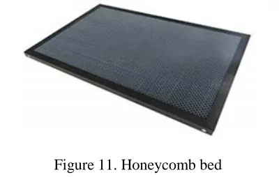
2. Honeycomb Bed.When the material to be cut is very thin or less rigid material like paper or fabric, a honeycomb bed is required to keep the material flat and the structure allows the heat and waste material caused by the process to escape as shown in Fig.11.
Figure 11. Honeycomb bed
3.
CONTROL UNITE
Control is very important in order to allow each component to do the required task at the desired time. Controlling a 3D printer is not an easy work because it is containing on a lot of hardware to be simultaneously coordinated.
• The movement of three axes has to be coordinated
• The filament being fed by the cold end has to be controlled.
• The temperatures of the hot end and the heated bed need to be monitored and adjusted.
• Finally, fans have to be turned on and off.
This all requires processing power, significant amounts of current being passed through the control board and the simultaneous control of multiple outputs and inputs.
A. Electronics Connect and Wiring
www.ijiset.com
55
16T
Figure12. control component wiring
B. Firmware
Marlin Firmware is an Open Source 3D printer and laser cutting software program, written using Arduino C language, licensed by GPL. It is uploaded on Arduino Mega board using USB cable to control the head of printer and laser. It is responsible for controlling the movement of the axis (its direction and feed rate), the temperature (reads temperature from sensors and control on and off of the heater block) and limit switches (position of zero of machine). In order to compile firmware and upload it to electronics:
1-Download the Arduino IDE from www.arduino.cc.
2-Download the Marlin firmware from https://github.com/ErikZalm/Marlin 3-Editing the Marlin configuration files for RAMPS.
IV. ASSEMBLING PROCEDURES
1. Take five parts of 2040 v-slot and they should be arranged as shown in the Fig. 13.
2. Make connections between every two elements by using corner 1 and corner 2 as shown in the Fig. 14.
3. Make connections with bolt in each corner and make assembly by angle in each corner as shown in the Fig.15.
4. Make four parts of guide wheel holder for Z axis as shown in the Fig.16.
5. Make the guide wheel part for Y axis by repeating the previous step and get 2 parts as shown in the Figure17.
www.ijiset.com
56
7. Put the 4 guide wheel parts of Z axis in the v-slots.8. Make assembly of motors of Z axis in their places with connection in v-slot by Z motors holder and with nuts and bolts as shown in the Fig.19.
9. Make assembly of bearing and screw bearing housing with screw bearing holder and screw bearing lock and connect them to the frame with nut and bolt as shown in the Fig.20.
10.Make assembly of screw with motor by connection of coupler as shown in the Fig.21.
11. Make assembly of screw and nuts as shown in the Fig.22.
12.Repeat steps 8,9,10, and 11 in every corner to get
Z axis with assembly of end of screw in bearing.
13.Make assembly of inside frames shown in the Fig.23.
14. Make assembly of two parts of guide wheel of y axis into inside frame.
15. Make assembly of two Y motors and bearing holder into frame by bolts and nuts shown in the Fig.24 and Fig.25.
16. Make assembly of x, y v-slot 2040 into inside frame.
17.Make assembly of X motor into frame as shown in the Fig.26. and assembly of belt holder.
18. Make assembly of belt between pulleys that connected with motor and bearing that make movement smoothing but you have to fi belt into X guide wheel with a clamp s shown in the Fig.27.
19. Make assembly of part that hold the laser head and hot end into the X guide wheel by bolts and nuts.
20.Make assembly of hot end and laser head into their part as shown in the Figure28.
Figure13. Assembly of frame
Figure14. One corner of
www.ijiset.com
57
Figure15. Assembly of the corner with assembling part
Figure16. Using angles in assembly
www.ijiset.com
58
Figure18. Guide wheel holder of y axis
Figure19. Assembly of Z motors
www.ijiset.com
59
Figure21. Assembly of screw with the coupler
with the motor
Figure22. Screw and nut
www.ijiset.com
60
Figure24. Assembly of Y motors
Figure25. Assembly of bearing holders
www.ijiset.com
61
Figure27. Belt with clamp
Figure28. Assembly of hot end and laser head
V. TECHNICAL SPECIFICATIONS
• Printer size 125cm X 125cm X 60 cm
• XY Resolution: 0.1mm • Layer Resolution: 0.1-0.3mm • Speed: 40mm/s, max 100mm/s • Wade style Extruder
• E3D All-metal v6 Hot End Full Kit - 1.75mm Universal (Direct) (12v)
• Nozzle diameter 0.4mm/0.5mm
www.ijiset.com
62
• G3D LCD display with G3D Shield including SD card reader and SD Card for standalone operation.• four points platform leveling
• Removable acrylic sheet for good adhesion and easy part removing • File Type: STL
• Firmware: Marlin
• 15W Laser Head Engraving Module • Cutting and engraving up to 6 mm in wood
VI.
CONCLUSIONThe integration of 3DP and Laser cutting device had been built in order to reduce the efforts and the waste time and it works appropriately. Based on this principle, this study did some experiments for obtaining the focal length of the Laser device. The type of laser module that we rely on it is 15-Watt, 450 nm laser focusing module which can cut 3 mm wood and engrave stainless steel and anode colored aluminum surface. A CAD model is constructed, and then converted to DXF format, The Laser machine processes the .DXF fie by creating lines and points related with power of laser of the model, The sheet is feed on the machine then select the zero work pieces from machine, and Start cutting and engrave lines and points from sheet to create final product.
VII. ACKNOWLEDGEMENT
The authors would like to thank the Academy of Scientific Research & Technology (ASRT) for supporting us financially and believing in our idea, and the authors would like to thank Made in Egypt (MIE) community for supporting us technically by providing the sessions we needed to carry on with our project. finally, we would thank All teaching staff in FEHU specially in Mechanical Department for the efforts they done along fie year past from now to help us getting ready to be good mechanical engineers.
VIII.REFERENCE
1. Hamoud M., “Surface Roughness Justification in Additive Manufacturing” 18th International Conference on Applied Mechanics and Mechanical Engineering- AMME-18, pp 185-195, Cairo, Egypt, April 3-5, 2018.
2. Hamoud M., “Enhancement of Sliced Layer Contour for Reconstructing A 3D Model Using Solid Freeform Fabrication” 18th International Conference on Applied Mechanics and Mechanical Engineering- AMME-18, pp 196-208, Cairo, Egypt, April 3-5, 2018.
www.ijiset.com
63
4. Mariana Kuhl Cidade, Felipe Luis Palombini, Lauren Cunha Duarte, and Sidnei Paciornik, “Investigation of the thermal microstructural effects of CO2 laser engraving on agate via X-ray microtomography”, Optics and Laser Technology, v104, pp 56-64, 2018.5. Bert Lauwers, Fritz Klocke, Andreas Klink, and A. Erman Tekkaya, Reimund Neugebauer, Don Mcintosh, “Hybrid processes in manufacturing ”, CIRP Annals - Manufacturing Technology, v63, pp561-583, 2014.