Experience of the Development of the Geometry
Database for the CBM Experiment
Elena Akishina1,Evgeny Alexandrov1, Igor Alexandrov1,Irina Filozova1,2,3,*, Volker Friese4, and Victor Ivanov1,5
1Laboratory of Information Technologies, Joint Institute for Nuclear Research, 6 Joliot-Curie, Dubna, Moscow region, 141980, Russia
2Dubna State Univeristy, 19 Universitetskaya, Dubna, Moscow region, 141982, Russia 3Plekhanov Russian University of Economics, 36 Stremyanny per., Moscow, 117997, Russia 4GSI Helmholtzzentrum für Schwerionenforschung GmbH, Planckstraße 1, 64291 Darmstadt, Germany
5National Research Nuclear University MEPhI, 31 Kashirskoe shosse, Moscow, 115409, Russia
Abstract. This paper is dedicated to the current state of the Geometry Database (Geometry DB) for the CBM experiment. The geometry DB is an information system that supports the CBM geometry. The main aims of Geometry DB are to provide storage of the CBM geometry, convenient tools for managing the geometry modules, assembling various versions of the CBM setup as a combination of geometry modules and additional files, providing support of various versions of the CBM setup. The development is based on the analysed users’ requirements (which were formulated in User Requirements Document) and takes into account peculiarities of the workflow for simulation of particle transport through the setup. Both the Graphical User Interface (GUI) and the Application Programming Interface (API) are available for the members of the CBM collaboration.
1 Introduction
The Geometry database (Geometry DB) supports the geometry of the CBM experiment at the detailed level required for simulation of particle transport through the setup using GEANT3 [1]. The motivation of this development is caused by the following reasons. There is a variety of detector modules: Muon Chambers (MuCh), Time-of-Flight System (TOF), Projectile Spectator Detector (PSD), Silicon Tracking System (STS), Micro Vertex Detector (MVD), Transition Radiation Detector (TRD), Ring Imaging Cherenkov Detector (RICH), Electromagnetic Calorimeter (ECAL), Magnet and Beam Pipe.
There are the di-electron and the di-muon versions of the CBM setup. In the di-electron version of the CBM setup RICH and TRD will provide a reliable registration of electrons/positrons with the momenta of more than 1 GeV. ECAL is used for electron/photon identification. In the di-muon version of the CBM setup for registration and identification of high-energy muons, the muon detection system MUCH is used. Together
with one coordinate plane of the TRD detector the MUCH is also used to reconstruct the trajectories of charged muons [2]. The evolution of geometries and variants must be taken into account in the design and the construction phases of the experiment. The geometry of the CBM modules is provided in ROOT files, each containing the top-level volume for the respective module. Each file comes with a running versioning tag, e.g. “sts_v15a.geo.root”. The same module can be used in different contexts, i.e. there are the setups with different placements. It is needed to provide the flexibility, i.e. to combine the different modules for the different setups (e.g., sis100_electron, sis100_muon). Finally, one has to manage this variety and flexibility and the evolution of geometries in a fail-safe, reproducible and transparent way.
The Geometry DB as an information system is aimed to the following tasks: to store the modules of CBM, to load the geometry modules for setup construction, to construct the setup from the stored modules and to support different versions of setup.
2 Design and implementation of the Geometry DB
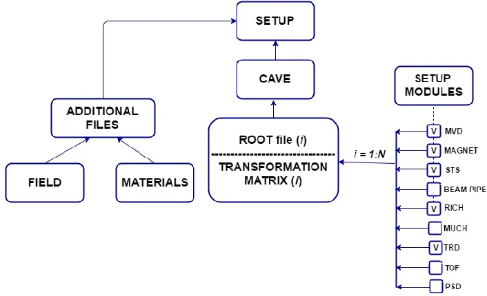
The issues dealing with the development of the requirements and the design of the Geometry DB are considered in detail in papers [2] and [3]. The specific of the developed information system is defined by the procedure of assembling of various CBM setup options. Fig.1. illustrates dynamic and flexibility aspects of geometry DB.
Fig. 1. The structure of the CBM setup.
with one coordinate plane of the TRD detector the MUCH is also used to reconstruct the trajectories of charged muons [2]. The evolution of geometries and variants must be taken into account in the design and the construction phases of the experiment. The geometry of the CBM modules is provided in ROOT files, each containing the top-level volume for the respective module. Each file comes with a running versioning tag, e.g. “sts_v15a.geo.root”. The same module can be used in different contexts, i.e. there are the setups with different placements. It is needed to provide the flexibility, i.e. to combine the different modules for the different setups (e.g., sis100_electron, sis100_muon). Finally, one has to manage this variety and flexibility and the evolution of geometries in a fail-safe, reproducible and transparent way.
The Geometry DB as an information system is aimed to the following tasks: to store the modules of CBM, to load the geometry modules for setup construction, to construct the setup from the stored modules and to support different versions of setup.
2 Design and implementation of the Geometry DB
The issues dealing with the development of the requirements and the design of the Geometry DB are considered in detail in papers [2] and [3]. The specific of the developed information system is defined by the procedure of assembling of various CBM setup options. Fig.1. illustrates dynamic and flexibility aspects of geometry DB.
Fig. 1. The structure of the CBM setup.
The Geometry Module is the file in ROOT format (ROOT file (i) in Fig. 1) with the content of the detector geometry. The Setup Module consists of Geometry module, link to mother Geometry module and transformation matrix. The transformation matrix (object of class TGeoMatrix) defines the module placement in the mother module. Setup is the combination of the setup modules that represents the full CBM geometry. So, the setup consists of a set of setup modules and additional files. The additional files include the detailed information on the distribution of the magnetic field inside and around the dipole magnet and a list of materials that makes up the CBM installation.
It must be mentioned that the details of any subdetector geometry are inside a root file. This means that CBM Geometry DB can be applied to other experiments with minimal changes. Currently NICA megaproject is very promising from this point of view as both experiments have similar software environment.
2.1 Functional model of Geometry DB
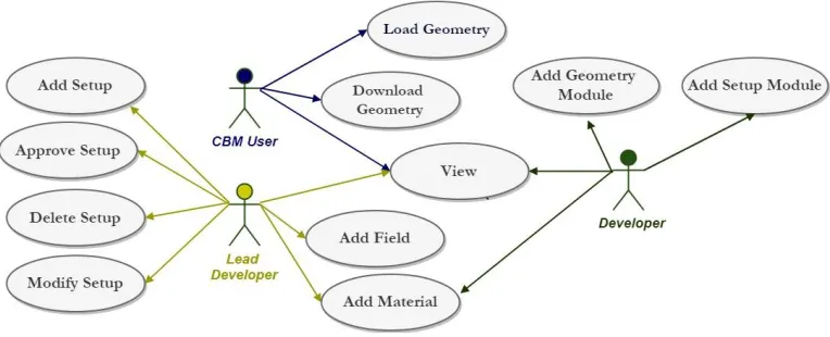
The functional model (Fig. 2.) of Geometry DB is described in paper [3].
Fig. 2. Use cases of the Geometry DB.
There are three roles: Lead Developer, Developer and CBM user. Their functions are defined in the URD [3]. The Lead Developer is a coordinator and responsible person for the entire Geometry DB. Only Lead Developer is able to delete or modify any setup, create new one, approve it since the setup is verified and can be used by CBM users. Lead Developer can add new versions of magnetic field and materials. The Developer is a person responsible for one of the setup modules. Both Developer and Lead Developer are able to create, edit or delete the setup module. The Lead Developer can modify any setup module while the Developer – only the setup module which he/she is responsible for. The CBM user is only able to: view the content of the Geometry DB; download the full setup or the setup module into local file system; load setup and download the database replica into CBM ROOT framework [4]. The functionality of the system provides interfaces to view, retrieve and update modules and setups; to store setup as a combination of setup modules, magnetic field and materials and to store setup modules as ROOT files and Transformation matrix.
2.2 Database development
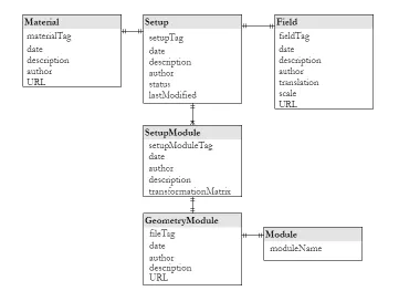
Keynote entities (real-world objects) and relationships between them were identified at the stage of conceptual database design. Then, the properties of each entity and relations between them were clarified (Fig.3).
Fig. 3. Logical ER-model of Geometry DB
Geometry module is just the reference to the root file and the Module is the short name of the Geometry module. Module names corresponds to short official names of CBM detector.
The entity Setup is the central in the developed database. Let’s consider it in more detail. The Setup relationship scheme: Setup(#id, stag, description, author, status, lastmodified), where
1) id — primary key, 2) stag — unique setup tag,
3) description — short setup description, 4) author — creator name of this setup,
5) status — short information about setup status
6) lastmodified — the date/time of the last Setup modification.
The attribute Status may have three possible values: “Created”, “Approved” and “Deleted”. The status “Created” is assigned after inserting a new setup record into database, “Approved” — after action Approve by the responsible person, “Deleted” — after action Delete, correspondently. Delete means to make this setup unavailable for the usage. The setup can be used by users when its status has the value “Approved”.
The general object model of system and logical Entity-Relationship Diagram are represented in the papers [2] and [4].
2.3 Architecture of the Geometry DB
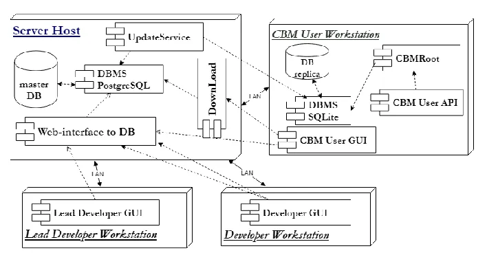
The Geometry DB is a distributed system (Fig.4). Web-server, database interface, Database Management System (PostgreSQL) and the primary data are located at the server host. The local database, CBMROOT and web-browser are placed at the workstation of the user. The CBM user interacts only with the local database, downloaded into the framework.
Fig. 4. General architecture of the Geometry DB.
For updating data files corresponding to any object of the Geometry DB the Lead Developer and the Developer interact only with Central Geometry DB.
The Local Geometry DB (SQLite) [5] is a replica of Central Geometry DB. This DB contains only approved setups. CBM user can load database into root environment only using local replica. Due to the small size of the database any number of local DBs can be performed. So, the scaling does not lead to the increasing of the time to load local DB into Root environment.
2.4 The implementation
Both GUI and API are available for the users. GUI is implemented as Web-interface and allows viewing, editing and downloading the data. API is realized as a set of macros in the ROOT framework. It permits to view the list of available setups and to load any setup into the ROOT framework.
2.4.1 The Web-interface implementation
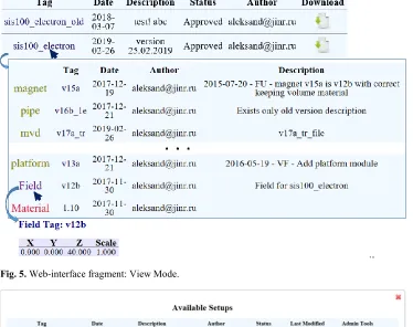
Web-interface is compact and intuitive. All CBM users are able to view and download the entire archived database file to the local disk. There is also a possibility to download any setup as archived file. The left sidebar supports the view mode. By clicking on the active items, user can go to the detailed information (Fig. 5.). So, from the list of available setups, the user can go to the level of detailed description of the setup, and further to the description of setup modules and additional elements. In the same way it is possible to view Materials and Fields.
The module “Configure Access” provides the functionality to manage user accounts and to configure their rights.
Fig. 5. Web-interface fragment: View Mode.
Fig. 6. Web-interface: Edit Mode.
It is also needed to select materials file and magnetic field from the available list (Fig. 7). When a new setup is constructed, Lead Developer pushes “Add Setup” button, and the new setup is compiled.
The interface for modifying the setup is similar. It is also possible to work with materials, magnetic field and setup modules.
2.4.2 The API implementation
The API is implemented as a set of macros of the CBM ROOT framework [6]. These macros are the standard ROOT macros and permit CBM users to obtain information about
Fig. 7. Web-interface: Form for adding a new setup.
the existing setups and to load the geometry of the selected setup into the memory of application. All CBM users can use the Geometry DB in their applications after downloading the entire archived database file to the local disk.
The user can run following macros: 1) macro for viewing list of approved setups and 2) macro for loading setup or setup subset into CBM ROOT environment.
The list of available macros:
void getSetupList()- get the list of available setups. Print the list of available setups
including tag, date of creation, author and description parameters for each approved setup.
Call Example: getSetupList.c();
bool loadSetup(const char* setupTag, const char* moduleName); - load setup
into the CBM ROOT framework. The Geometry can be used in ROOT framework afterwards. Return FALSE if setup is not loaded, and TRUE if the loading is successful.
Call Example: bool res = loadSetup("sis100_electron", "*");
bool loadSetup(const char* setupTag, int moduleId);- load setup into CBM
ROOT environment by module identifier. The Geometry can be used in ROOT framework afterwards. Return FALSE if setup is not loaded, and TRUE if loading is successful.
bool loadSetup(const char* setupTag, const char* moduleName, const char*
xml);- load setup into the ROOT environment. Geometry can be used in the ROOT
environment after this operation. User can use xml file in order to move any setup module during loading. Return false if setup was not loaded because of errors and true if load is successful.
XML file example:
The module is not shifted if there is no corresponding module type specified in the XML file.
Call Example: loadSetup("sis100_electron", "*", "local.xml");
The call with moduleName value * means that all setup modules to be loaded.
3 Conclusion
The Geometry DB prototype for the CBM experiment has been developed. The functionality of GUI depends on the role of the user. Only user with the privileged rights (Lead Developer and Developer) is able to edit the central database. CBM user is able to load the geometry from the local replicas using API. The scaling does not lead to the increasing of the time to load local DB into Root environment. It seems suitable to apply our experience of development the CBM Geometry DB to other experiments of high energy physics, in particular for the NICA megaproject.
References
1. R. Brun, F. Bruyant, M. Maire, A.C. McPherson, P. Zanarini, Geant3. - (CERN; CERN-DD-EE-84-1), 175 pages (1987).
2. E. Akishina, E. Alexandrov, I. Alexandrov, I. Filozova, V. Friese, V. Ivanov. Development of the Geometry Database for the CBM Experiment, PEPAN Letters, 1
(2018)
3. E. Akishina, E. Alexandrov, I. Alexandrov, I. Filozova, V. Friese, V. Ivanov, User Requirements Document of the Geometry DB for the CBM experiment, electronic publishing. Available at: http://lt-jds.jinr.ru/record/69336?ln=en.
4. E. Akishina, E. Alexandrov, I. Alexandrov, I. Filozova, V. Friese, V. Ivanov. Status of the geometry database for the CBM experiment, CEUR Workshop Proceedings, Vol-2023, pp.144-154 (2017).
5. SQLite official web-site. Available at: https://www.sqlite.org/.