Freeware Power Generation Structural
Implementation Strategy using Solar Panels in
Parallel Approach
Syeda Noor Fathima
1, Syed Thouheed Ahmed
2B.E 8th Sem, Dept. of Electrical & Electronics, Dr. T Thimmaiah Institute of Technology (Dr. TTIT), V.T.U, K.G.F,
Karnataka, India 1
Sr. Research Engineer, ThinkSoft Research & IT Consultancy Services Bangalore, Karnataka, India 2
ABSTRACT: As the energy demand is drastically increasing day by day all over the world. The reserves of fossil fuels like coal, oil and natural gas are depleting. To cope up with this unbalancing situation, we should keep more optimistic view about the renewable energy source. In India there is an abundant source of solar energy, this can be utilized in fulfilling the lower demands of the community. In this paper, solar energy is converted into electrical energy by photo voltaic effect hence a voltage is created appended to the load with an economical hardware and cost.
KEYWORDS:Solar panels (SP), Inverter Systems, Optimistic Power Generation Unit
I. INTRODUCTION
The direct conversion of solar energy into electrical energy by means of the photo voltaic effect that is the conversion of light into electric city. The PVE is defined as generation of electromotive force as a result of the absorption of ionization radiation. Energy conversion devices which are used to convert sunlight to electric city by the use of PVE are called solar cells. A single converter cell is called a solar cell or photovoltaic cell and the combination of such cells are designed to increase the electric power output is called solar module or solar array. In this paper we design a circuit to generate a 24V DC by using three 12V solar panels. By connecting the panels in parallel we can double the current by constantans in voltage. Here we avoid the usage of battery and backup’s to formulate an economical hardware. The voltage is given to the invertor circuit where it gets converted into 220V 50Hz AC power.
Photovoltaic cells produced by the majority of today’s most large producers are mainly made of crystalline silicon as semiconductor material. Solar PV modules, which are a result of combination of photovoltaic cells to increase their power, are highly reliable, durable and low noise devices to produce electricity. The fuel for the photovoltaic cell is free. The sun is the only resource that is required for the operation of PV systems, and its energy is almost inexhaustible
II. SYSTEM CONFIGURATION
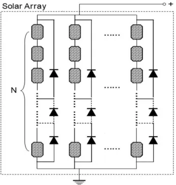
The developed PV power system, as shown in Fig. 1, has two main characteristics. 1) In contrast to conventional configurations characterized as many cells in series, with or without bypass diodes (shown in Fig. 1), the PV array in the system described here adopts a highly parallel configuration. 2) The MPPT is implemented through controlling the PV array operating voltage to follow a prescribed voltage reference corresponding to the single-cell MPP.
Fig. 1.PV array using conventional configuration.
1) Parallel Configuration
The PV array is constructed with a highly parallel, rather than serial, wiring configuration. The highly parallel configuration has three important characteristics 1) The voltage of the MPP is largely independent of illumination, or in other words, even at different irradiance levels, the MPPs of cells connected in parallel occur at nearly a common voltage. 2) Slight deviation from MPP voltage only weakly affects produced power. 3) Voltage of the MPPs is only weakly sensitive to temperature over the usual range (e.g.,20-K difference). As a consequence, the parallel-configured PV array is capable of making every cell in the panel generate nearly maximum power simultaneously, no matter whether the illumination distribution is uniform. Different cells in the panel may supply different currents corresponding to irradiance levels falling on them instantly; however, all the cells share a common voltage that will be controlled to track the MPP
2) MPPT
tracking speed (typically a couple of seconds), it is not easy to implement directly in portable PV applications since the energy generated from partially shaded cells cannot be collected, and the tracking speed is not fast enough for portable applications where shading conditions may changes rapidly (e.g., tenth of a second).
On the other hand, the MPP of any individual cell is actually rather simple to locate since it is located very near to a particular (temperature dependent) operating voltage [1]. Based on this well-known fact, the MPPT methodology of controlling PV array operating voltage was already developed a few decades ago for series-connected PV arrays [7]–[6]. It is easy to implement and has fast dynamic response to illumination changes. For series connected cells, although, uniform illumination is a precondition to make this method work well; shaded cells will defeat the technique because they will reduce the target operating voltage. Therefore, for portable applications, this technology cannot be directly applied if the PV panel were connected using conventional series configurations.
Fig 2: Basic Block Diagram
III. EXPERIMENTAL SETUP
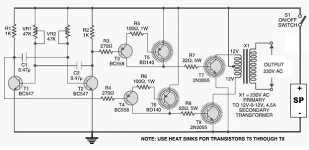
This circuit is designed with eight transistors and a few resistors and capacitors. Transistors T1 and T2 (each BC547) form an astable multivibrator that produces 50Hz signal. The complementary outputs from the collectors of transistors T1 and T2 are fed to PNP Darlington driver stages formed by transistor pairs T3 BC558 , T4 BC558 , T5 BD140, and T6 BD140.
Fig 3b: Inverter Circuit Block Diagram
The outputs from the drivers are fed to transistors T7 and T8 (each 2N3055) connected for push-pull operation. Suitable heat-sinks for transistors T5 ,T6, T7 & T8 is used to dissipated the heat generated by these transistors . A 220V AC primary to 12V-0-12V, 4.5A secondary transformer (X1) is used. The center-tapped terminal of the secondary of the transformer is connected to the Solar panels which are connected in parallel so as to produces 12V 4Amps, while the other two terminals of the secondary are connected to the collectors of power transistors T7 and T8,respectively.
When we power the circuit using switch S1, transformer X1 produces 230V AC at its primary terminal. This voltage can be used to glow an 11W to 15W CFL Lamp used as a load. The circuit is assembled on a general purpose PCB and housed in a suitable cabinet. Solar panels and transformer is connected with suitable current-carrying wires. On the front panel of the box power switch S1 and a 3-pin socket for connecting the CFL Lamp is fitted.
IV. RESULTS AND CONCLUSION
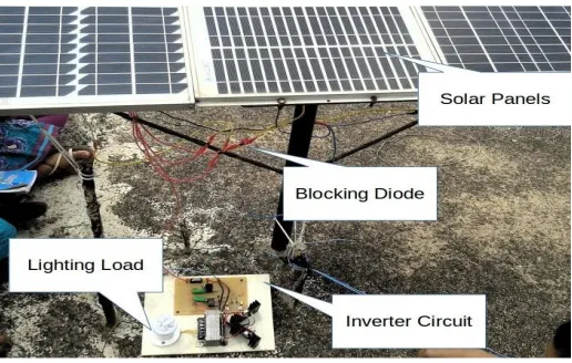
Solar cells are long lasting sources of energy which can be used for prolonged time. The solar rays are directly converted into AC using an inverter circuit, which is accompanied by an astable multivibrator generates a frequency of 50Hz. Since battery usage is avoided, the bulky unit is reduced lading in weight loss in entire system making it cost efficient and economical in the presents of sunrays. With an experimental setup as shown in fig 4, for 3 Solar panel array a generation of 230V is successfully observed with a lighting load of 11W CFL.
REFERENCES
[1] B. E. A. Saleh and M. C. Teich, Fundamentals of Photonics. NewYork: Wiley, 1991.
[2] R. Dougal, L. L. Gao, S. Liu, and A. Iotova, “Apparatus and method for enhanced solar power generation and maximum power point tracking,” Patent PCT Number WO 2007/124059 A2, Nov. 2007.
[3] L. Gao, R. A. Dougal, S. Liu, and A. Iotova, “Portable solar systems using a step-up power converter with a fast-speed MPPT and a parallelconfigured solar panel to address rapidly changing illumination,” in Proc. IEEE APEC, Anaheim, CA, Mar. 2007, pp. 520–523.
[4] H. Koizumi and K. Kurokawa, “A novel maximum power point tracking method for PV module integrated converter,” in Proc. IEEE PowerElectron. Spec. Conf., 2005, pp. 2081–2086.
[5] H. Oldenkamp, I. Jong, N. Borg, B. Boer, H. Moor, and W. Sinke, “PV Wirefree versus conventional PV systems: Detailed analysis of difference in energy yield between series and parallel connected PV modules,” in Proc. 19th Eur. Photovoltaic Solar Energy Conf., Paris, France, Jun. 2004. [6] W. Xiao, N. Ozog, and W. G. Dunford, “Topology study of photovoltaic interface for maximum power point tracking,” IEEE Trans. Ind.
Electron., vol. 54, no. 3, pp. 1696–1704, Jun. 2007.
[7] R. Gules, J. De Pellegrin Pacheco, H. L. Hey, and J. Imhoff, “A maximum power point tracking system with parallel connection for PV stand-alone applications,” IEEE Trans. Ind. Electron., vol. 55, no. 7, pp. 2674–2683,Jul. 2008.
[8] O. Wasynczuck, “Dynamic behavior of a class of photovoltaic power systems,” IEEE Trans. App. Syst., vol. PAS-102, no. 9, pp. 3031–3037, Sep. 1983.
[9] M. Calais and H. Hinz, “A ripple-based maximum power point tracking algorithm for a single-phase, grid-connected photovoltaic system,” Sol. Energy, vol. 63, no. 5, pp. 277–282, Nov. 1998.
[10] N. Femia, G. Petrone, G. Spagnuolon, and M. and M. Vitelli, “Optimization of Perturb and observe maximum power point tracking method,” IEEETrans. Power Electron., vol. 20, no. 4, pp. 963–973, Jul. 2005.
BIOGRAPHY