Manual Pigging with Improved Safety using
Microcontroller based Passcode Lock
T.Kiruthikaa
1, M.Bharathi
2PG Student [EIE], Dept. of EIE, Bharath University, Chennai, Tamilnadu, India1
Professor, Dept. of EIE, Bharath University, Chennai, Tamilnadu, India 2
ABSTRACT:Pigging, the pipeline cleaning process in oil and gas industries is very risky. Pig, a line size plug is propelled in the pipeline to remove the scales and debris. So many fatal accidents happened so far during the removal of pig from the pipeline. Safety is very important than anything. This paper deals about providing a cost effective simple easily adaptable solution to avoid accidents during the removal of pig. A passcode open lock is provided at the closure for safety. The passcode will be generated using a microcontroller reading the safe conditions like position of the valves and pressure in the receiver using proximity and pressure sensors. The passcode will randomly change and will be displayed when the condition is safe. The closure cannot be opened without passcode. Thus we can improve the safety and avoid accidents.
KEYWORDS:Pigging, pig, passcode generator, electro pneumatic lock, proximity sensor, pressure sensor, microcontroller
I.INTRODUCTION
In oil and gas industries the pipeline cleaning is mandatory as there is constant deposition of scales and debris in the pipeline. This may block the pipeline and affect the flow. For cleaning they adapt a process called pigging. In pigging process they send a line size swab inside the pipeline to remove the scales and debris. Most of the time, pigging is an online process. The pipeline flow fluid is used as the propelling fluid for the pig. The pipeline pressure is in the order of several 1000 psi. To remove the pig from the pipeline, the pipeline handling several 1000 psi pressure should be opened. Hence it’s a dangerous process. Some carelessness may lead to fatal accidents. So far so many accidents have happened. There are so many smart techniques available in the market to provide smart pigging. But still manual pigging is done in most industries. Hence we plan to provide a cost effective simple solution which can be easily adapted by the operator without any need for special training to prevent the accidents.
II.RELATED WORK
A launcher or receiver station is typically a vessel connected in parallel to the existing pipeline. This makes it possible to launch or receive the pig using the pipeline’s normal operating pressure and without interrupting the flow or stopping production.
The vessel is equipped with a closure door to load or offload a pig. By leading the process through the launcher station, the pig will be launched and pushed through the pipeline to be received at the other end in the receiver station.
A. Launching Procedure
Fig 1. PigLauncher
1. Ensure isolation and launch-line (kicker line) valves are closed.
2. Open vent and drain valves to allow liquid displacement or vent to atmospheric pressure.
3. When the pressure gauge on launcher reads zero psi, and with drain and vent valves in open position, open closure.
4. Insert pig and push forward until nose or front of the pig is firmly in contact with the reducer
5. Close and secure closure
6. Close the drain valve and gradually open kicker valve, venting through vent valve.
7. When launcher is full, close vent valve and allow pressure to equalize.
8. Open isolation valve.
9. Gradually close main line valve, thereby increasing flow behind pig.
10. Monitor pig detector for pig passage.
11. Once pig has entered main line completely, open main line valve fully.
12. Close kicker and isolation valves.
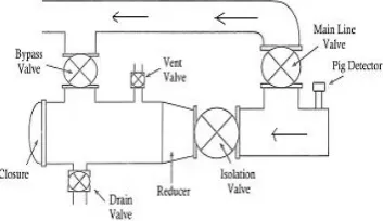
B.Receiving Procedure
Fig 2. Pig Receiver
1. Open bypass and isolation valves.
2. Partially close main line valve.
3. Monitor pig detector for pig reception.
5. Close bypass and isolation valves.
6. Open vent and drain valves.
7. .By checking pressure gauge for zero psi, ensure receiver is depressurized.
8. Open closure.
9. Remove pig.
10. Close and secure closure.
Several safety measures can be taken on the closure doors to prevent opening under pressure and by using written procedures but this is no guarantee that all of the above is taken into consideration. Throughout the years many accidents happened all over the world during this dangerous maintenance operation. Even though some larger valves are equipped with a MOV the process cannot be fully automated since there is manual labour involved in loading and offloading the pig. According to statistics, “70% of the reported incidents in the oil and gas industry worldwide are attributable by human error”. People can be trained to follow procedures and informed about potential danger but a mistake cannot be excluded.
III. PROPOSED METHODOLOGY
My project is to provide a solution to minimize the human error during the pig reception. As discussed in the introduction, before opening the closure safely, there are several basic safety criteria that need to be met.
1. The vessel must be drained and depressurized.
2. The vessel must be isolated from the process pipeline by closing the Kicker lines and the main valves. 3. In case of a closed drain systems and/or vent headers the vessel must also be isolated by closing the drain and
vent valves.
4. The vessel needs to be free from toxic gasses like H2S.
5. At the same time the vessel must remain isolated when the door is open
6. When the launching or receiving procedure starts the closure should be properly closed.
This paper deals about providing a cost effective simple easily adaptable solution to avoid accidents during the removal of pig. A passcode open lock is provided at the closure for safety. The passcode will be generated using a microcontroller reading the safe conditions like position of the valves and pressure in the receiver using proximity and pressure sensors. The passcode will randomly change and will be displayed when the condition is safe. The closure cannot be opened without passcode. Thus we can improve the safety and avoid accidents.
IV.EXPERIMENTAL RESULTS
Fig.4.Flow Chart
Pressure sensor at the receiver - If there is pressure behind the pig while opening the pig will come out with high speed which is not safe. We place a sensor behind the pig to read the pressure behind the pig. When the pressure is at the safe level the sensor will give an output, and the light in the local check list panel will be on.
Proximity sensor at bypass valve - The bypass valve should be closed so that the receiving end will be disconnected from main line. A proximity sensor will be placed at the bypass valve. When the valve is closed the sensor will send signals and the light in the local check list panel will be on.
Proximity sensor at Isolation valve - The isolation valve should be closed so that the receiving end will be disconnected from main line. A proximity sensor will be placed at the bypass valve. When the valve is closed the sensor will send signals and the light in the local check list panel will be on.
Proximity sensor at Drain valve - The Drain valve should be opened so that the pressure inside the receiving end will be drained. A proximity sensor will be placed at the drain valve. When the valve is opened the sensor will send signals and the light in the local check list panel will be on.
Proximity sensor at vent valve - The vent valve should be opened so that the pressure inside the receiving end will be drained. A proximity sensor will be placed at the vent valve. When the valve is opened the sensor will send signals and the light in the local check list panel will be on.
Fig.5. Local check list Panel
8051 Micro controller - The 8051 micro controller will make the light in the local panel to on /off according to the sensor output. According to the sensor output, if the condition is safe to remove the pig, the controller will select a passcode and display it in LCD display.
Fig.6. Microcontroller and LCD display
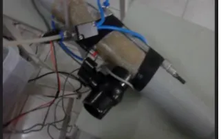
Electronic Lock - Electronic lock will be unlocked when the passcode displayed in the LCD display is given to the electronic lock keypad.
Fig. 7. Keypad for entering passcode to open the lock
Fig. 8. The closure is secured with the lock
Fig.9. The lock is opened on giving the passcode
V. CONCLUSION
A model of manual pigging is done in a two inch pipeline. The microcontroller is programmed to provide passcode when the valves are the in the safe position and the pressure is safe to operate. When the passcode is entered in the keypad the lock is opened as expected.
VI. FUTURE SCOPE
We have proposed one simple cost effective easy to adapt solution which doesn’t need any special training solution for the operator to ensure the safety before opening the closure member at the receiving end. In future we also have to provide same sort of cost effective solution to prevent accident at the launching end of pig.
REFERENCES
[1] Multi-diameter, bi-directional pigging for pipeline pre-commissioning - Aidan O'Donoghue, PPSA Conference Aberdeen, November 2009 [2] Pigging as a Flow Assurance Solution Avoiding Slug Catcher Overflows - Aidan O'Donoghue, PPSA Conference Aberdeen, November 2005 [3] Estimating Pigging Frequency for Dewaxing - Aidan O'Donoghue, Pipelssssine Pigging Conference, Amsterdam, May 2004
[4] Latest Design Techniques for Dual and Multi diameter pigs - Aidan O'Donoghue, Pipeline Pigging Conference, Houston, January 2001 [5] Dynamic Simulation of the NorneHeidrun 10" x 16" Dewatering Pig - Aidan O'Donoghue, Pipes and Pipeline International, January/February
2001