2nd Int. Workshop Irradiation of Nuclear Materials: Flux and Dose Efects November 4-6, 2015, CEA – INSTN Cadarache, France
Centre of Excellence for Nuclear Materials
Microstructure Evolution in Fe and Fe-Cr Alloys with OKMC Methods
Maria J. CATURLA
1, Maria J. ALIAGA
1, Ignacio MARTIN-BRAGADO
2, Ignacio DOPICO
3,
Lorenzo MALERBA
3, Mercedes HERNANDEZ-MAYORAL
41
Dept. Física Aplicada, Facultad de Ciencias, Fase II, University of Alicante (Alicante, Spain)
2
IMDEA Materials Institute, Getafe (Madrid, Spain)
3
SCK-CEN, Nuclear Materials Science Institute (Mol, Belgium)
4
CIEMAT, Division of Materials (Madrid, Spain)
The type of damage observed under transmission electron microscopy (TEM) in b.c.c. Fe and FeCr alloys under irradiation is very dependent on the irradiation conditions. At high doses the damage consists mostly of ½ <111> and <100> loops, which are considered to be of interstitial type [1, 2]. Depending on the type of irradiation and the irradiation conditions, the ratio of one type of loop with respect to the other changes, with situations in which only one of the two types of loops are observed. The formation of <100> loops is still a controversial issue, with different models arising in the last few years. Experimentally, even the nature of these loops (vacancy or interstitial type) is still under debate under certain situations. Moreover, the type of irradiation (ion implantation vs. neutron irradiation) also changes the type and distribution of these defects.
In an attempt to shed some light into this complex system, we have developed models to study the damage of Fe and FeCr under irradiation. We combine results from density function theory (DFT), molecular dynamics (MD) and object kinetic Monte Carlo (OKMC) to study the production and evolution of the damage to time scales that can be directly compared to experiments. In this work we will discuss one particular issue: the differences between ion implantation and neutron irradiation. Currently, ion implantation is commonly used to obtain information about defect production and defect evolution, in an attempt to build models for neutron damage. We will point out the differences and commonalities between the two types of irradiation in the particular case of Fe, and those aspects that should be taken into consideration when building models for neutron irradiation from information obtained from ion implantation.
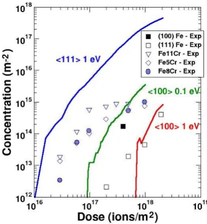
We will describe results of damage evolution in Fe using two different models for <100> loop formation: one where <100> loops are formed from the interaction between ½ <111> loops (based on simulations by Marian [3] and Terentyev [4]) and a second one where two populations of loops are formed directly in the collision cascade and evolve independently. This last model is based on the observation of stable immobile clusters from DFT calculations [5]. The population of loops formed as a function of dose for different irradiation conditions is explored and results compared to experiments. The validity of the models and the influence of the different parameters are discussed. In particular, we will study how the mobility of <111> interstitial loops changes both the total concentration of visible defects as well as the ratio of <111> vs. <100> loops and compare the results with experimental data available, as shown in the Fig. 1. In this case the experiments
are from reference [1]. Figure 1: OKMC simulations (solid lines)
compared to experiments from ref. [1]
EPJ Web of Conferences 115, 03001 (2016) DOI: 10.1051/epjconf/201611503001
© Owned by the authors, published by EDP Sciences, 2016
2nd Int. Workshop Irradiation of Nuclear Materials: Flux and Dose Efects November 4-6, 2015, CEA – INSTN Cadarache, France
2
Centre of Excellence for Nuclear Materials
Finally we will discuss how object kinetic Monte Carlo can be modified to study high concentrated alloys for the particular case of FeCr.
References
[1] Z. Yao, M. Hernández Mayoral, M. L. Jenkins, M. A. Kirk, Heavy-ion irradiations of Fe and Fe-Cr model alloys Part 1: Damage evolution in thin-foils at lower doses, Phil. Mag. 88 (2008) 2851. [2] M.L. Jenkins, Z. Yao, M. Hernández-Mayoral, M.A. Kirk, Dynamic observations of heavy-ion
damage in Fe and Fe-Cr alloys, J. of Nucl. Mat. 389 (2009) 197–202.
[3] J. Marian, B. D. Wirth and J. Manuel Perlado, Mechanism of formation and growth of <100> interstitial loops in ferritic materials, Phys. Rev. Lett. 88, 25 (2002).
[4] Haixuan Xu, Roger E. Stoller, Yuri N. Osetsky and Dmitry Terentyev, Solving the puzzle of <100> interstitial loop formation in bcc iron, Phys. Rev. Lett. 110, 265503 (2013).
Microestructure Evolution in Fe and FeCr alloys with
OKMC methods
M. J. Aliaga
1, I. Martin-Bragado
2, I. Dopico
3, L. Malerba
3,
M. Hernández-Mayoral
4, M. J. Caturla
11
Dep. Física Aplicada, Universidad de Alicante, Spain
2IMDEA Materials Institute, Getafe, Madrid, Spain
3
SCK-CEN, Belgium
4CIEMAT, Madrid, Spain
Motivation:
validate models with ion implantation – extrapolate
to neutron irradiation
Reproduce and explain ion and neutron
implantation experiments in Fe and FeCr
Z. Yao, et al., Phil. Mag. 88, 2851 (2008)
http://jannus.in2p3.fr/
Intermediate Voltage
Electron Microscope
(IVEM) Tandem
facility at ANL (USA)
:
MD database + DFT data → OKMC →
damage in bulk and thin films
•
Interstitials
•
Vacancies
70 nm
100 keV Fe recoil in bulk
100 keV Fe recoil in thin film
OKMC
MD
+ DFT
Exp
.
Vacancies Self-interstitials
C. C. Fu et al. Nature Mat. (2004)
•
J. Marian,
PRL 2002
New methods/models are emerging
at all levels
Treating
electronic
effects from
first
principles
Jorge
Kohanoff
First passing KMC
Primary damage: influence on microstructure evolution
Fe 30keV, 66 defects Cu 30keV, 69 defects
Similar number of defects but more vacancy clustering in Cu than in Fe
This has important consequences in the subsequent damage evolution
1014 1015 1016 1017 1018
10-5 10-4 10-3 10-2 10-1 100
Damage Accumulation in Copper
kMC: V>1.5 nm
Fusion Neutrons Spallation Neutrons Fission Neutrons Protons
C
o
n
c
e
n
tr
a
ti
o
n
(
c
m
-3)
Dose (dpa)
Damage accumulation in Cu and Fe compared to experiments
Simulations explain the basic differences observed experimentally in Cu and Fe:
nucleation of vacancy clusters in Cu together with fast migration of self
interstitials, the presence of traps in Fe and the visibility under TEM
1014 1015 1016 101710-5 10-4 10-3
Copper
Iron
C
lu
s
te
r
D
e
n
s
it
y
(
c
m
-3)
Dose (dpa)
Damage accumulation in Cu and Fe
Fe calculations – N. Soneda
www.kit.edu
Influence of initial cascade damage distribution
on damage accumulation
(Carolina Björkas, Univ. Helsinki)
Question addressed: Is the long term evolution of defects affected by the
picosecond cascade damage distribution or does it only depend on migration and
binding energies?
30keV Fe in bcc Fe
NO EXPERIMENTAL VALIDATION OF MD RESULTS ON SINGLE CASCADE DAMAGE
OKMC calculations using cascade
damage distributions from 3 different
interatomic potentials, AMS [1], DD-BN
[2,3] and MEA-BN [3, 4]
[1] G. J. Ackland, M. I. Mendelev, et al. J. Physics: Condens. Matter, 16 (2004) [2] S. L. Dudarev and P.
M. Derlet. J. Phys.: Condens. Matter, 17 (2005) [3] C. Bjorkas and K. Nordlund, Nucl. Instrum. & Meth. B
259 (2007) [4] M. Muller, P. Erhart, and K. Albe, J. Phys.: Condens. Matter, 19 (2007)
Influence of initial cascade damage distribution
on damage accumulation
(Carolina Björkas, Univ. Helsinki)
OKMC simulations
TOTAL DEFECT CONCENTRATION:
no significant difference between the three potentials
I > 5 mobile <111> + traps (0.9 eV)
www.kit.edu
Influence of initial cascade damage distribution
on damage accumulation
(Carolina Björkas, Univ. Helsinki)
VISIBLE DEFECT CONCENTRATION:
only those clusters of interstitials > 55 (loop of 1nm radius)
only those clusters of vacancies > 350 (void of 1nm radius)
Large differences are now observed between the three potentials
I > 5 mobile <111>
+ traps (0.9 eV)
25
50 KeV
Cluster size
Energy
96
100 keV
Cluster size
Energy
Differences in cluster size distribution with int.
potential
(Carolina Björkas, Univ. Helsinki)
AMS potential predicts
significantly larger
self-interstitial clusters at 50keV
cascades
Interstitial
clusters
AMS DD-BN MEA-BN10 30 50 70
90
Cluster size
SIA AMS Potential
SIA MEA Potential
www.kit.edu
Experimental validation of models
Multiscale modeling can only work with the
proper experimental validation
Z. Yao, et al., Phil. Mag. 88, 2851 (2008)
Intermediate Voltage
Electron Microscope
(IVEM) Tandem
facility at ANL (USA)
:
http://www.ne.anl.go
v/ivem/
In-situ TEM analysis of
irradiation
MD simulations of irradiation in Fe thin films
Enhanced production of vacancy loops, mostly <100>
Irradiation of thin films at low energies (50-150keV) show the formation of
large (~1nm radius) <100> vacancy loops. Mostly square loops as expected
from energy considerations (Gilbert et al J.Phys:Cond.Mat. 2008)
Thin film irradiation with
100keV Fe ions
Simulating damage in metals: surface vs. bulk irradiation
Bulk irradiation with 100keV PKA in Fe
◐
Bulk irradiation shows the formation of self-interstitial loops
◐Some large vacancy loops are also observed.
◐
Note the sub-cascade formation
Vacancies
Interstitials
Statistical analysis of MD cascades
Cluster size differences between bulk and thin films
◐
Significant difference between the size of the clusters in bulk and thin
films for the same energy
◐
Vacancy clusters much larger in thin films (> 100 defects)
◐Self-interstitial clusters significantly larger in bulk irradiation
Damage produced by Ga ions in Fe at low energies (30keV)
Thin film irradiation with
30keV Ga ions
Heavier ion (Ga) produces much larger vacancy clusters also of <100>
type even at lower energies (30 keV), in agreement with experiments, M.
L. Jenkins Nature (1976) & Z. Yao Phil. Mag. 2008
Modeling damage accumulation in Fe: OKMC
OKMC code – MMonCa from IMDEA-Materials
I. Martin-Bragado, et. al. Computer Physics Comunications (2013). /
www.materials.imdea.org/MMonCa
MMonCa – OKMC code
All individual defects can be resolved
Energetics from
M R Gilbert et al, J. Phys.:
Condens. Matter 20 (2008)
345214
Small defects
Vacancies and Self-interstitials up to 4
Energetics from C. C. Fu, Nat. Mat.
4
(2005) 68
• 17
Defect-defect interaction in OKMC
<100> vs. <111> self-interstitial loops
100 keV Fe implantation in thin film
Sample
50-100nm
Model A
J. Marian [1]
D. Terentyev [2]
Formation of <100> by
interaction between <111> loops
of the same size
Model B
Marinica [3]
Growth of two independent loop
populations
5% <100> - 95% <111>
[1] J. Marian et al. PRL 88, 25 (2002).
[2] H. Xu, R. Stoller, Y. Osetsky, D. Terentyev, PRL 110, 265503 (2013).
[3] M.-C. Marinica, F. Williaime, J.-P. Crocombette, PRL 108, 025501 (2012).
[4] N. Soneda, T. Diaz de la Rubia, Phil. Mag. A 81 (2001) 331
<111> loop mobility from
Soneda [4]
• 18
OKMC of 100keV Fe implantation in Fe and FeCr
Reference experiments
Yao et al.
Phil Mag.
(2008)
Effect of different parameters:
Mobility of <100> loops
Model A: minimum <111> loops to <100>
Model B: ratio of <100> vs. <111> loops
Presence of traps (binding of 0.8 eV)
Mobility of <111> loops
Evaluate the defects obtained from the two models
Thickness ~ 50nm
Pure Fe: mostly <100> loops
at low dose
• 19
OKMC of 100keV Fe implantation in Fe and FeCr
<100> Vacancy loops
<100> Vacancy loops immobile
<100> Vacancy loops mobile
Concentrations too high compared
to experimental measurements
• 20
OKMC of 100keV Fe implantation in Fe and FeCr
Model A vs. Model B – no Carbon
Model A: <111>+<111> -> <100>
Model B: 5% <100>, 95% <111>
Without Carbon all loops are of
<100> type with both models
Concentrations are too high
compared to experimental
measurements
• 21
OKMC of 100keV Fe implantation in Fe and FeCr
Model B – effect of initial distribution of loops
Model B:
5.0% <100>, 95.0% <111>
0.1% <100>, 99.9% <111>
Distribution of only 0.1% of the
small Interstitial clusters (< 4) as
seeds for <100> loops gives loops
concentrations in closer agreement
to experimental values for (100)
orientation
Rate of growth of loops with dose in
agreement with experimental
• 22
OKMC of 100keV Fe implantation in Fe and FeCr
Model B – effect of <111> mobility
Model B:
<111> E
m~ 0.1eV
<111> E
m= 1 eV
Two population of loops:
<111> and <100>
Densities close to values for FeCr
More <111> than <100> loops
Problems with the saturation of
loops at high doses:
loop-loop interaction capture radius
or long range interactions must be
www.kit.edu
OKMC model for concentrated alloys
1. T
he alloying element is not treated discretely but in terms of
concentration
2. Jump rates of particles are not fixed: will depend on the
location of the particle and the enviroment.
1
C
1
2
C
2
…
…
i C
i
i+1
C
i+1…
N
C
N
L. MALERBA & M. J. CATURLA
C
1
C
2
1
2
4
Do all these mechanisms just add up?
1 + 1 = 2 ?
500 kev cascade in Fe
E. Zarkadoula et al,
www.kit.edu
Simulating interfaces and complex systems
Fréchard et. al. JNM (2009)
TEM image of a martensitic steel
after He implantation
What we want to achieve:
Modeling concentrated
alloys, interfaces (grain
boundaries) and
Conclusions
Primary damage plays a major role in the subsequent
microstructure evolution
Surface effects must be taken into account when
comparing to in-situ TEM ion implantation:
–
Damage production could be affected by the
presence of surfaces (low energy irradiation)
–
Damage evolution will be affected due to
preferential trapping by surfaces or image forces.
More complex and detail simulations: loop size and type.