1126 | P a g e
COMPARISIONAND REALIZATION OF
MICROSTRIP BAND PASS AND BAND REJECT
FILTER AT GSM BAND (850MHz) USING
DGS-TECHNIQUE
Richa Chaturvedi
1, Dr.Laxmi Shrivastava
2Department of electronics and communication Engineering, Madhav institute of technology and
science, Gwalior
ABSTACT
Filters are essential high frequency components in microwave communication system. The filters are
use
for
communication
purpose,
satellite
communication
as
well
as
in
radar
communication.A bandpass filter is adevice that allows signals to pass between two specific
frequencies,but that supressed against signals at other frequencies.
.
This paper introduces a compact
band stop and band pass filters using DGS for size reduction technique,which is improved by the DGS
technique.This DGS technique is proposed version of conventional (circular-head) and slotted ground
to improve the performance of filters.A (five pole hairpin) microstrip band pass filter is designed with
GSM band center frequency i.e. 850Mhz,as well as the band reject (open circuit stub)filter is having
the same frequency,The insertion loss is improved in the band pass filter as well as band stop filter
through the DGS technique.In this paper improved results have been obtained by comparing 850Mhz
normal with 850Mhz(DGS) in band pass filter as well as in band stop filter,the improved results
showing sharp roll off. The insertion lossof band pass filter and band reject filters are improved by
applying the DGS technique.The filters are simulated using CST software 2010.
Keywords- Band pass filter, Band stop filter, Defected ground structure i.e.(circular head and
slotted ground),CST (computer simulation technology)
I. INTRODUCTION
Combline for the realization of band pass filters have been presented.There is a disadvantage of parallel coupled
line Filters are used for communication purpose. There is a requirement of mobility of components and
equipment in mobile communication systems [1]. A DGS technique is very popular technique for reducing the
size of the filters and achieved the properties of filters like insertion loss.Thus DGS-filters structure has the
advantage of compact size and low cost [2].In band pass filter the design is based on Chebyshev response as
Butterworth filter is less selective than that of Chebyshev response[2].The cut off frequency of the structure with
this slot can be controlled by adjusting the distance, without changing the area occupied by the slot[3].To
1127 | P a g e
aperture].PBG(Photonic Band Gap) is a structure which is designed to reject the particular frequency band.
Because of difficulties in modeling and radiation from the periodic etched defects, PBG structures can not be
used for the microwave components designing[2].The Band pass filters are the important components to
overcome the losses in the microwave for rejecting the undesired frequencies[4].As well as in the band stop
filter provide the desired frequencies.DGS disturbs the defending current distribution, which change the
inductance and capacitance of the line.The series inductance is increased by DGS which in turn increases the
reactance of microstrip at cut-off, high Q with low cost and size and low insertion loss. Numerous design
techniques such as parallel coupled line, split ring resonators (SRR) and filter.It suffers from spurious response
which degrades the pass band and stop band performance of the filter, Split ring resonators suffers from large
from large circuit losses and large frequency variation[2]. The filters using the DGS circuit has a number of
attractive features, which include the following.
1)The stopband is very wide and more deeper than that of a conventional low-pass filter.
2) The structure is very simple
3)Extremely small element values for implementation filter can be realized.
4) The insertion loss is very low[5]
In this paper the band pass and band stop filters are designed of GSM band i.e,850Mhz which is the center
frequency of 800-900 Mhz .A five pole haipin band pass filter is designed with circular head DGS as well as
without DGS whereas a open band stop open circuited (slotted ground)is designed with or withoutDGS.To
improve the insertion loss of the filters and achieve sharpe cut-off.
II. Design
2.1 Design of Hairpin band pass filter-
In the band pass filter by without DGS the dimensions of the filters are having 10cm×8.5cm.The
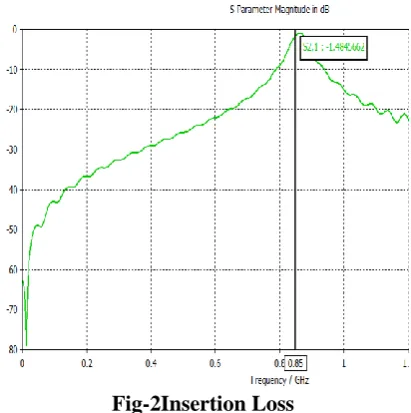
insertion loss of this filter is -1.4845dB.
1128 | P a g e
Fig-2Insertion Loss
In this figure thesimulated insertion loss of band pass filter wihout DGS is shown i.e, -1.4845dB
2.2. Various DB-DGS pattern
Fig.3 (1) Triangular head (2) Sqare head (3) circular head (4) Hexagonal head.
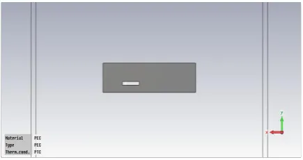
2.3Design of Band pass filter with DGS Technique(circular-head)-
Fig 4-Circular head Shape
Table-1 Dimension of circular head –
Dimensions in mm Circular
R 0.3
G 0.8
1129 | P a g e
Hairpin filter is obtained by folding the parallel half wavelength resonators in dumbbled-shape,The microstrip
dumbbled-shape filtersare very popular because they have simple structure[5].The circular-head DGS technique
is used in the design.Here the combination of capacitor and inductor used for modeling the resonators.
Qe1=g0g1/FBW (1) Qen=gngn+1/FBW (2) Mi,i+1=FBW/gigi+1 for i=1 ton-1(3)
Where the Qe1 and Qenshowing the quality factors of input and output, Mi,i+1 showing the mutual
coupling between the resonators.And the FBW (fractional bandwidth)=BW/f0=0.206dB at center frequency
850Mhz .The parameters are used for determine the gap and size in Hairpin filter which can be derived from
theseequations.The dimensions of the filter have 10cm×8.5cm,center frequency of the band pass filter have
850Mhz,substrate thickness (h)=1.6,Di-eleltric constant εr=4.4 mm,Band pass ripple=0.1 Db, characterstics line
impedence Z0=50 ohm, normalized frequency Ωc=1,Number of poles=5,circular head pole=2,fractional
banwidth of filter is= FH-FL/FC i.e, 0.995-0.82/0.85=0.206dB.
Where FH is the high frequency,FL is the low frequency and Fc is cut-off frequency.
M12=M45=0.1307
M23=M34=0.076
Qe1=Qe5=5.5669
The coupling coefficient can be varied by varying the spacing between the resonators by using the formula
K= (f22-f12)/(f22+f12)
The spacing required quality factor can be obtained by using the above formula where f1 and f2 are the two
peak resonance. These frequencies are obtained from the simulated response S21 for resonators.
The elements values are-
The five pole hairpin filters have parameters g1=go=1.0, g1=g5=1.1468,g2=g4= 1.3712 and g3=1.9750.These
values are used to determine the design parameters of band pass filter.By using DGS technique the results are
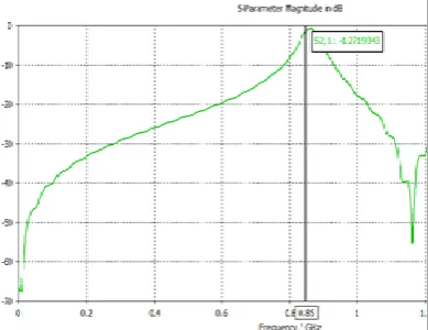
improved, insertion loss is shifted from –1.4845dB to -1.27193dB
.
Design for the filter-
Fig.5-U-shape structure
N g
1g
2g
3g
4g
5g
61
0.3052 1.0
2
0.8431 0.6220 1.3554
3
1.0315 1.1474 1.0315 1.0
4
1.1088 1.3062 1.7704 0.8181 1.3554
1130 | P a g e
Filters are constructed by U-shape structure.These U-shape structures are obtained by folding the resonators of
half-wave length resonator filter and parallel-coupled
.
Fig. 6: Improved insertion loss of band pass filter with DGS
In this figure the simulated insertion loss of band pass filter with DGS is shown i.e, -1.27dB.
III. DESIGN OF BAND REJECT FILTER
The length and width of the filters have 16.7cm×4cm.The insertion loss is -42.47dB.The dielectric constant of
substrate (FR4-LOSSY) εr=4.4mm,loss tangent=0.0025 are used in design configuration.
Fig7- Band reject filter-
1131 | P a g e
In this figure the simulated insertion loss of band reject filter wihout DGS is shown i.e, -42.47Db
IV. DESIGN OF BAND REJECT FILTER WITH DGS
All thefilters are designed using 50Ω microstrip line. The size of band pass reject fixed are kept fixed which is
16.7cm×4cm.The dielectric constant of substrate(FR4-LOSSY) εr=4.4mm,loss tangent=0.0025,conductor height
is=1.53mm are used in design configuration.The simulated results are shown in fig
.7
The insertion loss of the band is improved by using DGS technique i.e, -44.61dB.In order to design the band
stop filter with a sharpe cut-off,DGS slot is used.The slot consists of 9cm×3.5cm Performance of filter depend
upon the number of factors such as slotted ground, shape radius and position of DGS.
Fig. 9: Band reject filter with slotted
ground-Fig-10 Improved insertion losswith DGS
In this figure the simulated improved insertion loss of band reject filter with DGS is shown i.e,-44.61dB.
RESULTS
Table2: Comparison of filter’s results-
FILTERS WITHOUT DGS
(INSERTION LOSS)
WITH DGS
(INSERTION LOSS)
Band pass -1.4845Db -1.27193Db
Band Reject -42.47dB -44.6165Db
The filters are simulated with CST software 2010.The band pass and band reject center frequency is
1132 | P a g e
FABRICATED RESULTS-V. CONCLUSION
In this paper,the performance of filters is improved by using DGS-structure.The insertion loss of filter is
improved by designing BPF (Band pass filter) and BRF (Band reject filter) with DGS technique. Good
agreement was achieved.
REFERENCES
[1] Boutejdar, Ahmed. "Design of Compact Reconfigurable Broadband Band-Stop Filter Based on a Low-Pass
Filter Using Half Circle DGS Resonator and Multi-Layer Technique." Progress In Electromagnetics
1133 | P a g e
[2] Vidhya, K., and T. Jayanthy. "Design of microstrip hairpin band pass filter using defected ground structure
and open stubs." In 2011 international conference on information and electronics engineering IPCSIT, vol.
6. 2011.
[3] Balalem, Atallah, Ali R. Ali, Jan Machac, and Abbas Omar. "Compact band-stop filter using an interdigital
DGS structure." In Microwave Techniques, 2008. COMITE 2008. 14th Conference on, pp. 1-3. IEEE, 2008.
[4] Annam, Kaushik, Sunil Kumar Khah, Steven Dooley, Charles Cerny, and Guru Subramanyam.
"Experimental design of bandstop filters based on unconventional defected ground structures." Balalem,
Atallah, Ali R. Ali, Jan Machac, and Abbas Omar. "Compact band-stop filter using an interdigital DGS
structure." In Microwave Techniques, 2008. COMITE 2008. 14th Conference on, pp. 1-3. IEEE,
2008. Microwave and Optical Technology Letters 58, no. 12 (2016): 2969-2973.
[5] Kershaw, Vivek Singh, Sarita Singh Bhadauria, and Geetam Singh Tomar. "Design of Microstrip
Hairpin-Line Bandpass Filter with Square Shape Defected Ground Structure." (2017).
[6] Ahn, Dal, J-S. Park, C-S. Kim, Juno Kim, Yongxi Qian, and Tatsuo Itoh. "A design of the low-pass filter
using the novel microstripdefected ground structure." IEEE transactions on microwave theory and