ISSN (Print) : 2320 – 3765 ISSN (Online): 2278 – 8875
I
nternational
J
ournal of
A
dvanced
R
esearch in
E
lectrical,
E
lectronics and
I
nstrumentation
E
ngineering
(An ISO 3297: 2007 Certified Organization)
Vol. 4, Issue 5, May 2015
Electricity Generation by Speed Breaker
G.Ramakrishna Prabu, G.Ethiraj
Associate Professor, Dept of EEE, VMKV Engg College, Salem, Tamil Nadu, India
PG Scholar, Dept of EEE, VMKV Engg College, Salem, Tamil Nadu, India
ABSTRACT: Energy is the primary need for survival of all organisms in the universe. Everything what happens in the surrounding is the expression of flow of energy in one of the forms. But in this fast moving world, population is increasing day by day and the conventional energy sources are lessening. The extensive usage of energy has resulted in an energy crisis over the few years. Therefore to overcome this problem we need to implement the techniques of optimal utilization of conventional sources for conservation of energy. This project includes how to utilize the energy which is wasted when the vehicles passes over a speed breaker. Lots of energy is generated when vehicle passes over it. We can tap the energy generated and produce power by using the speed breaker as power generating unit. The kinetic energy of the moving vehicles can be converted into mechanical energy of the shaft through rack and pinion mechanism. Then, this mechanical energy will be converted to electrical energy using generator which will be saved with the use of a battery. The energy we save during the day light can be used in the night time for lighting street lights. Therefore, by using this arrangement we can save lot of energy which can be used for the fulfillment of future demands.This project harvests energy from speed breaker by making gear arrangement and using electronic gadgets. Large amounts amount of electricity can be generated saving lot of money. And if implemented will be very beneficial for Government.When vehicle is in motion it produces various forms of energy like, due to friction between vehicle‟s wheel and road i.e. rough surface HEAT Energy is produced, also when vehicle traveling at high speed strikes the wind. The principle involved is potential energy to electrical energy conversion. There is a system to generate power by converting the potential energy generated by a vehicle going up on a speed breaker into kinetic energy. When the vehicle moves over the inclined plates, it gains height resulting in increase in potential energy, which is wasted in a conventional rumble strip. When the breaker comes down, they crank a lever fitted to a ratchet-wheel type mechanism (a angular motion converter) which in turn rotates a geared shaft loaded with recoil springs. The output of this shaft is coupled to a dynamo to convert kinetic energy into electricity.
I. INTRODUCTION
Increasing demand of energy adds to the need of identifying non-conventional resources of energy. In my paper, I will discuss about power generation from speed breaker and the possible mechanism required for it.An energy crisis is any great bottleneck (or price rise) in the supply of energy resources to an economy. It usually refers to the shortage of oil and additionally to electricity or other natural resources. An energy crisis may be referred to as an oil crisis, crisis, energy shortage, electricity shortage electricity crisis. While not entering a full crisis, political riots that occurred during the 2007 Burmese antigovernment protests were initially sparked by rising energy prices. Likewise the Russia-Ukraine gas dispute and the Russia-Belarus energy dispute have been mostly resolved before entering a prolonged crisis stage.
Market failure is possible when monopoly manipulation of markets occurs. A crisis can develop due to industrial actions like union organized strikes and government embargoes. The cause may be ageing over-consumption, infrastructure and sometimes bottlenecks at oil refineries and port facilities restrict fuel supply. An emergency may emerge during unusually cold winters. EMERGING SHORTAGES Crisis that currently exist include. The availability of regular conventional fossil fuels will be the main sources for power generation, but there is a fear that they will get exhausted eventually by the next few decades. Therefore, we have to investigate some approximate, alternative, new sources for the power generation, which is not depleted by the very few years. Another major problem, which is becoming the exiting topic for today is the pollution. It suffers all the living organisms of all kinds as on the land, in aqua and in air. Power stations and automobiles are the major pollution producing places.
ISSN (Print) : 2320 – 3765 ISSN (Online): 2278 – 8875
I
nternational
J
ournal of
A
dvanced
R
esearch in
E
lectrical,
E
lectronics and
I
nstrumentation
E
ngineering
(An ISO 3297: 2007 Certified Organization)
Vol. 4, Issue 5, May 2015
renewable energy such as solar wind), OTEC (ocean thermal energy conversions) etc…for power generation. The latest technology which is used to generate the power by such renewable energy” POWER HUMP”.
II. LITERARY SURVEY
1 THE BURGER KING ON U.S. HIGHWAY, CUSTOMERS PULLS IN AND OUT ALL DAY, AND AT LEAST 100,000 CARS VISIT THE DRIVE-THRU EACH YEAR. AND A NEWLY INSTALLED,
MECHANIZED SPEED BUMP(VIDEO) WILL BOTH HELP THEM SLOW DOWN AND HARVEST SOME
OF THAT COASTING ENERGY.
The weight of a car is used to throw a lever, explains Gerard Lynch, the engineer behind the MotionPower system developed for New Energy Technologies, a Maryland-based company. "The instantaneous power is 2,000 watts at five miles-per-hour, but it's instantaneous which means some form of storage will be required.
Fig 1: Speed Bump
2 JOURNAL OF ENGINEERING RESEARCHANDSTUDIES.PRODUCE ELECTRICITY BY THE USE OF SPEED BREAKERS. ASWATHAMAN.V, ELECTRONICS AND COMMUNICATION ENGINEERING SONA COLLEGE OF TECHNOLOGY, SALEM, INDIA
This paper attempts to show how energy can be tapped and used at a commonly used system- the road speed breakers. The number of vehicles passing over the speed breaker in roads is increasing day by day. A large amount of energy is wasted at the speed breakers through the dissipation of heat and also through friction, every time a vehicle passes over it. There is great possibility of tapping this energy and generating power by making the speed-breaker as a power generation unit. The generated power can be used for the lamps, near the speed breakers. The utilization of energy is an indication of the growth of a nation. For example, the per capita energy consumption in USA is 9000 KWh (Kilo Watt hour) per year, whereas the consumption in India is 1200 KWh (Kilo Watt hour). One might conclude that to be materially rich and prosperous, a human being needs to consume more and more energy. A recent survey on the energy consumption in India had published a pathetic report that 85,000 villages in India do not still have electricity. Supply of power in most part of the country is poor. Hence more research and development and commercialization of technologies are needed in this field. India, unlike the top developed countries has very poor roads. Talking about a particular road itself includes a number of speed breakers. By just placing a unit like the “Power Generation Unit from Speed Breakers”, so much of energy can be tapped. This energy can be used for the lights
on the either sides of the roads and thus much power that is consumed by these lights can be utilized to send power to these villages.
ISSN (Print) : 2320 – 3765 ISSN (Online): 2278 – 8875
I
nternational
J
ournal of
A
dvanced
R
esearch in
E
lectrical,
E
lectronics and
I
nstrumentation
E
ngineering
(An ISO 3297: 2007 Certified Organization)
Vol. 4, Issue 5, May 2015
The rotor (rotating shaft) is directly connected to the prime mover and rotates as the prime mover turns. The rotor contains a magnet that, when turned, produces a moving or rotating magnetic field. The rotor is surrounded by a stationary casing called the stator, which contains the wound copper coils or windings. When the moving magnetic field passes by these windings, electricity is produced in them. By controlling the speed at which the rotor is turned, a steady flow of electricity is produced in the windings. These windings are connected to the electricity network via transmission lines. IIT Guwahati has evaluated the machine and recommended it to the Assam ministry of power for large scale funding. IIT design department says it is a „very viable proposition‟ to harness thousands of megawatts of electricity untapped across the country every day. A vehicle weighing 1,000 kg going up a height of 10 cm on such a rumble strip produces approximately 0.98 kilowatt power. So one such speed-breaker on a busy highway, where about 100vehicles pass every minute, about one kilo watt of electricity can be produced every single minute. The figure will be huge at the end of the day. A storage module like an inverter will have to be fitted to each such rumble strip to store this electricity. The cost of electricity generation and storage per megawatt from speed-breakers will be nearly Rs 1 crore as opposed to about Rs 8 crores in thermal or hydro power stations.
III. EXISTING METHODS
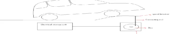
FIG 2: Basic Outline of system
The project is concerned with generation of electricity from speed breakers-like set up. The load acted upon the speed breaker - setup is there by transmitted to rack and pinion arrangements. Here the reciprocating motion of the speed-breaker is converted into rotary motion using the rack and pinion arrangement. The axis of the pinion is coupled with a gear. This gear is meshed a pinion. As the power is transmitted from the gear to the pinion, the speed that is available at the gear is relatively multiplied at the rotation of the pinion.
The axis of the pinion is coupled to a gear arrangement. Here we have two gears with different diameters. The gear (larger dimension) is coupled to the axis of the pinion. Hence the speed that has been multiplied at the smaller sprocket wheel is passed on to this gear of larger dimension. The pinion is meshed to the gear. So as the gear rotates at the multiplied speed of the pinion, the pinion following the gear still multiplies the speed to more intensity. Hence, although the speed due to the rotary motion achieved at the first gear is less, as the power is transmitted to gears the speed is multiplied to a higher speed. This speed is sufficient to rotate the rotor of a generator.
The rotor which rotates within a static magnetic stator cuts the magnetic flux surrounding it, thus producing the electric motive force (emf). This generated emf is then sent to a bridge rectifier, where the generated AC current is converted to DC. This regulated emf is now sent to the lead-acid battery
Disadvantages:
Shafts are required to be mounted on bearings which creates balancing problem.
Mechanical vibrations which in turn damage the bearings.
ISSN (Print) : 2320 – 3765 ISSN (Online): 2278 – 8875
I
nternational
J
ournal of
A
dvanced
R
esearch in
E
lectrical,
E
lectronics and
I
nstrumentation
E
ngineering
(An ISO 3297: 2007 Certified Organization)
Vol. 4, Issue 5, May 2015
IV. PROPOSED SYSTEM
1. BLOCK DIAGRAM:
Fig 3: BLOCK DIAGRAM
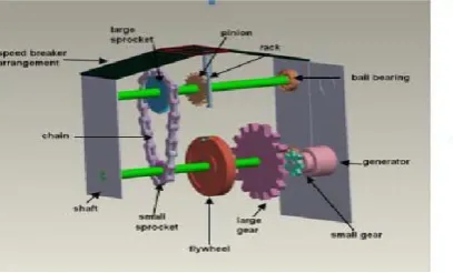
2. CONSTRUCTION DETAILS:
The various machine elements used in the construction of power hump are
RACK
SPUR GEAR
FLY WHEEL
BEARINGS
SHAFT
SPRINGS
ELECTRIC DYNAMO
A dome is mounted on four springs and in the bottom, a rack is clamped. The rack consists contact teeth on both the faces. It is connected to two gear wheels to rotate the gear wheels only in one direction. We have inserted a free wheel in each gear. The free wheel and the gear assembly are mounted centrally. The flywheel is also mounted on the same shaft and the shaft is simply supported at the both ends by means of ball bearings. Now a dynamo is connected to each shaft by belt drive. The output terminal of dynamo is connected to an electrical storing device. The total assembly is arranged in concrete pit.
3. WORKING:
ISSN (Print) : 2320 – 3765 ISSN (Online): 2278 – 8875
I
nternational
J
ournal of
A
dvanced
R
esearch in
E
lectrical,
E
lectronics and
I
nstrumentation
E
ngineering
(An ISO 3297: 2007 Certified Organization)
Vol. 4, Issue 5, May 2015
While moving, the vehicles possess some kinetic energy and it is being wasted. This kinetic energy can be utilized to produce power by using a special arrangement called POWER HUMP. It is an Electro-Mechanical unit. It utilizes both mechanical technologies and electrical techniques for the power generation and its storage. POWER HUMP is a dome like device likely to be speed breaker. Whenever the vehicle is allowed to pass over the dome it gets pressed downwards then the springs are attached to the dome are compressed and the rack which is attached to the bottom of the dome moves downward in reciprocating motion.
Fig 5: SCHEMATIC DIAGRAM
Since the rack has teeth connected to gears, there exists conversion of reciprocating motion of rack into rotary motion of gears but the two gears rotate in opposite direction. A flywheel is mounted on the shaft whose function is to regulate the fluctuation in the energy and to make the energy uniform. So that the shafts will rotate with certain R.P.M. these shafts are connected through a belt drive to the dynamos, which converts the mechanical energy into electrical energy. The conversion will be proportional to traffic density. Whenever an armature rotates between the magnetic fields of south and north poles, an E.M.F (electro motive force) is induced in it. So, for inducing the E.M.F armature coil has to rotate, for rotating this armature it is connected to a long shaft.
Byrotating same e.m.f, is induced, for this rotation kinetic energy of moving vehicles is utilized. The power is generated in both the directions; to convert this power into one way a special component is used called zenor diode for continuous supply. All this mechanism can be housed under the dome, like speed breaker, which is called HUMP. The electrical output can be improved by arranging these POWER HUMPS in series. This generated power can be amplified and stored by using different electrical devices
4. POWER CALCULATIONS:
RACK AND PINION CALCULATIONS:
Module = Pitch Circle Diameter/ Number of teeth = 36/18 = 2 mm Pitch Circle Radius(r) = 36/2 = 18 mm
Addendum (a) = module = 2 mm
Addendum Circle Radius (ra) = r + addendum = 18 + 2 = 20mm Pressure angle of pinion (Φ) = 14.5° involute
Length of path of contact = (a/sin Φ) + { [ra^2 – (r sin Φ)^2]} ^0.5 - r sin Φ = 13.29 mm Length of arc of contact = Length of path of contact / sin Φ = 13.75 mm
Minimum number of teeth in contact = Length of arc of contact / πm = 2 Angle turned by the pinion = Length of arc of contact x 360 / 2πra = 39.39° Minimum Length of rack = 2πra = 125.66 mm
SPUR GEAR:
It is a positive power transmission device with definite velocity ratio. In volute teeth profile is preferred for adjusting some linear misalignment. It should have high wear and tear, shock-absorbing capacity.
Gear Specifications
ISSN (Print) : 2320 – 3765 ISSN (Online): 2278 – 8875
I
nternational
J
ournal of
A
dvanced
R
esearch in
E
lectrical,
E
lectronics and
I
nstrumentation
E
ngineering
(An ISO 3297: 2007 Certified Organization)
Vol. 4, Issue 5, May 2015
• Number of Teeth (N) = 76
• Pitch Circle Diameter (D) = Do /(1+2/N) = 155/ (1+2/76) = 151 mm • Module = D/N = 151/ 76 =2 mm
• Pressure angle of gear (Φ) = 14.5°
• Diametral Pitch (P) = N/D = 76/151 = 0.5 mm • Addendum (a) = 1/P = 1/0.5 = 2 mm
• Dedendum (b) = 1.157/P = 1.157/0.5 =2.31 mm • Tooth Thickness = 1.5708/ P = 1.5708 / 0.5 =3.14 mm • Whole Depth = 2.157/P = 2.157/0.5 = 4.314 mm • Clearance = 0.157/ P = 0.157/0.5 = 0.314 mm
• Center Distance = (N1 + N2)/ (2*P) = (76 + 18 )/ (2* 0.5) = 94 mm • Working Depth = 2/P = 2/0.5 = 4 mm
• Addendum Circle Diameter = D + 2m =151 + 2(1.98) = 154.96 mm • Dedendum Circle Diameter = D – 2.5m = 151 -2.5(1.98) = 146.05 mm
PINION SPECIFICATIONS:
• Outside Diameter ( Do ) = 40 mm • Number of Teeth (N) = 18
• Pitch Circle Diameter (D) = Do / (1+2/N) = 40/ (1+2/18) = 36 mm
• Module = D/N = 36/ 18 =2 mm
• Pressure angle of pinion (Φ) = 14.5°
• Diametral Pitch (P) = N/D = 18/36 = 0.5 mm • Addendum (a) = 1/P = 1/0.5 = 2 mm
• Dedendum (b) = 1.157/P = 1.157/0.5 =2.31 mm • Tooth Thickness = 1.5708/ P = 1.5708 / 0.5 =3.14 mm • Whole Depth = 2.157/P = 2.157/0.5 = 4.314 mm • Clearance = 0.157/ P = 0.157/0.5 = 0.314 mm
• Center Distance = (N1 + N2)/ (2*P) = (76 + 18 )/ (2* 0.5) = 94 mm • Working Depth = 2/P = 2/0.5 = 4 mm
• Addendum Circle Diameter = D + 2m =36 + 2(2) = 40 mm • Dedendum Circle Diameter = D – 2.5m = 36 -2.5(2) = 31 mm
DESIGN OF GEARS:
(1)Power to be transmitted from 1st shaft to 2nd shaft (P) = 0.18 KW Number of teeth on gear (z2) = 76
Number of teeth on pinion (z1) = 18 Speed of gear (n2) = 70 rpm Speed of pinion (n1) = 280 rpm
Velocity Ratio (i) = n1/n2 = Z2/Z1 = 4
2) Design
a) Tangential tooth load
Ft = 9550 x 1000 x P x Cs / n1 r1
= 9550 x 1000 x 1.22 x 1.5 / 1120 x 18m = 866.88 / m
b) Lewis Equation for tangential tooth load Ft = σob y p Kv
Face Width (b) = 10m Circular Pitch (p) = πm
Ft = (137) (10m) (0.086) (πm) Kv = 370.14m2 Kv
ISSN (Print) : 2320 – 3765 ISSN (Online): 2278 – 8875
I
nternational
J
ournal of
A
dvanced
R
esearch in
E
lectrical,
E
lectronics and
I
nstrumentation
E
ngineering
(An ISO 3297: 2007 Certified Organization)
Vol. 4, Issue 5, May 2015
= π x m x 18 x 1120 / 60000 = 1.055m
Equating equations (i) and (ii) 370.14m2 Kv = 866.88 / m
m3Kv= 2.34
Trial 1 :
Select module m = 1 mm vm= 1.055 x 1 = 1.055 m/sec
Velocity Factor Kv= 3 / 3 + vm= 3 / 3 + 1.055 = 0.739 [vm< 7.5 m/sec] From equation (iii)
(1)3 (0.739) ≥2.34
0.739< 2.34
Trial 2 :
Select module m = 2 mm vm= 1.055 x 2 = 2.11 m/sec
Velocity Factor Kv= 3 / 3 + vm= 3 / 3 + 2.11 = 0.58 [vm< 7.5 m/sec] From equation (iii)
(2)3 (0.58) ≥2.34
4.64> 2.34 ... Module m = 2 mm
c) Check for the stress
Allowable Stress σall= (σo1 Kv)all = (137) (0.58) = 79.46 N/mm2
Induced Stress σind= (σo1 Kv)ind = Ft / b y1 p
= [866.88 / 2] / (10 x 2) (0.086) (π x 2)
= 40.1 N/mm2 Since (σo1 Kv)ind< (σo1 Kv)all , the design is safe.
1) Identify the weaker member
Lewis form factor for 14.5° involute y = 0.124 – 0.684/z
Lewis form factor for pinion y1 = 0.124 – 0.684/ z1 = 0.124 - 0.684/18 = 0.086 Lewis form factor for gear y2 = 0.124 – 0.684/ z2 = 0.124 - 0.684/76 = 0.115 Allowable stress for pinion and gear σo= 137 MPa
σo y1= (137) (0.086) = 11.78
σoy2= (137) (0.115) =15.75
Since σo y1 <σoy2 , pinion is weaker. Therefore design should be based on pinion.
(2)Power to be transmitted from 2nd shaft to 3rd shaft (P) = 1.22 KW Number of teeth on gear (z2) = 76
Number of teeth on pinion (z1) = 18 Speed of gear (n2) = 280 rpm Speed of pinion (n1) = 1120 rpm Velocity Ratio (i) = n1/n2 = Z2/Z1 = 4
SHAFTS:
It is a rotating element, which is used to transmit power from one place to another place. It supports the rotating elements like gears and flywheels. It must have high torsional rigidity and lateral rigidity.
SHEAR STRESS IN THE SHAFT
It is calculated using the torsion equation-
T/J = τ/ r Where, T – Torque Transmitted (N-mm)
ISSN (Print) : 2320 – 3765 ISSN (Online): 2278 – 8875
I
nternational
J
ournal of
A
dvanced
R
esearch in
E
lectrical,
E
lectronics and
I
nstrumentation
E
ngineering
(An ISO 3297: 2007 Certified Organization)
Vol. 4, Issue 5, May 2015
τ - Shear stress (N/mm2)
r – Radius of the shaft (mm) T/ (πd^4/32) = τ/(d/2)
Torque Transmitted (T) = Force x Radius of shaft = 150 x 9.81 x 19 = 27958.5N-mm 27958.5/[π(19^4)/32] = τ / (38/2) Shear stress (τ) = 41.51 N/mm
V. CIRCUIT DIAGRAM
VI. HARDWARE IMPLEMENTATION
ISSN (Print) : 2320 – 3765 ISSN (Online): 2278 – 8875
I
nternational
J
ournal of
A
dvanced
R
esearch in
E
lectrical,
E
lectronics and
I
nstrumentation
E
ngineering
(An ISO 3297: 2007 Certified Organization)
Vol. 4, Issue 5, May 2015
6.2 OUTPUT:
Generator output without load
Generator output with load (Battery)
Battery output
VII. ADVANTAGES
ISSN (Print) : 2320 – 3765 ISSN (Online): 2278 – 8875
I
nternational
J
ournal of
A
dvanced
R
esearch in
E
lectrical,
E
lectronics and
I
nstrumentation
E
ngineering
(An ISO 3297: 2007 Certified Organization)
Vol. 4, Issue 5, May 2015
By using this method, electricity will be generated throughout the year without depending on other factors. Easy for maintenance and no fuel transportation problem.
Pollution free power generation.
Less floor area required and no obstruction to traffic. No need of manpower during power generation.
VIII. CONCLUTION
"Electricity plays a very important role in our life”. Due to population explosion, the current power generation has become insufficient to fulfill our requirements. In this project we discover technology to generate electricity from speed breakers in which the system used is reliable and this technique will help conserve our natural resources. In coming days, this will prove a great boon to the world, since it will save a lot of electricity of power plants that gets wasted in illuminating the street lights. As the conventional sources are depleting very fast, it‟s high time to think of alternative resources. We got to save the power gained from the conventional sources for efficient use. So this idea not only provides alternative but also adds to the economy of the country.
REFRENCES
[1]. Sharma.P.C ,Principle of renewable energy systems (Public printing service, New Delhi, 2003). [2]. Sharma.P.C, Non-Conventional power plants (Public printing service, New Delhi, 2003).
[3]. Mukherjee.DChakrabarti.S, Non-conventional power plants (Public printing service, New Delhi, 2005).
[4]. Ankita, MeenuBala, Power Generation From Speed Breakers, International Journal Of Advance Research In Science and Engineering, 2(2),
2013.