REVIEW ON COMPUTER AIDED ENGINEERING OF
WORK ROLL CHOCK AND BACKUP ROLL CHOCK
IN COLD ROLLING MILL
Snehal Nemade
1, D.D. Baviskar
2, G.M. Lonare
3 1M.E. Scholar,
2Assistant Professor,
3Associate Professor BVCOE Kharghar Mumbai (India)
ABSTRACT
The process of reduction of thickness of metal by passing it through the rolls called as the metal rolling. Rolling
is widely used thickness reduction process, which can have high production figures and precise control of final
product. Rolling is classified in two major types the cold rolling and hot rolling. Every part has its own theory,
development of rolling process and consequently the designing of the cold rolling mill components, like rolls
and rolling mill housing. The present paper studies to understand the various methodologies which are used to
design the cold rolling mill. We have concentrated on the history of the rolling process; it is understand that the
rolling process was adopted since year 1590. Though it was raw method but it initiated the slitting rolling mill
and the actual experimentation were started from year 1670. In those days rolling was concerned with rolling of
bars only after few years the rolling of bars were started In year 1783, after the entry of grooved rolls the rolling
production increased up to 15 times and that was the start of modern rolling mill. We have studied the different
parameters and factors that affect the roll design. While designing of rolling mill housing, we study the load that
comes on the rolls during the rolling operations and how it affects the bearing life and chock life. The finite
element analysis method is used for weight reduction of chock which is major part for failure.
Keywords: Cold Rolling, Plastic Deformation, Design Methodologies, Housing, Rolls, Split End,
Central Burst
I. INTRODUCTION
Design of rolling mill is a hard-hitting process where the designer should have clear knowledge and
understanding of the rolling process. There are various contradictory goals which need to satisfy, many
investigations need to be done for the complete analysis [1] Chocks are almost invariably the highest stressed
component in a manufactured item, and so are most susceptible to invariable the financial losses incurred as a
result of chock failure will be far greater than the actual value of the chock instantiated delivery of chocks
because of manufacturing presetting failure could stop a production failure at the assembly stage is almost
certain to halt production if only one or two chocks out of a large batch tailback no manufacturer would
willingly assemble goods that are suspecting failure in serviceable the most catastrophic consequences example
failure of cold rolling mill chock is very likely to result in the complete destruction of the cold rolling mill.
Failure of chocks in a cold rolling mill is basically because of higher stressed generated during start up and shut
maximum load acting on a chock to prevent from a failure fatigue failure beachwear of cyclic loading is also a
criteria of chocks design. Second most important function of the work as an isolator case of cold rolling mill
also it has to perform this function. So design chock hold has a required stiffness to transmit a vibration from a
source to receiver. So while designing a chock for cold rolling mill two factors is very important i.e. strength of
chock to sustain a maximum load and stiffness of a chock to transmit lesser vibration.
II. LITERATURE SURVEY
KatyalPuneet [1], in his thesis „Stress analysis and optimization of rolling mill housing using CAE‟ studied the
optimization of Rolling Mill Housings design for rigidity, to control the deflection of the housing for better gage
control of the material being rolled. The Housing stress distribution has been analyzed using analysis software
CATIA from which maximum static stress at critical areas have been calculated.
This study clearly concluded that, further work can be done so that housing experiences the same stresses at all
sections which then be called a balanced housing. Further dimensions of the balanced housing can be proposed
with respect of the components like chocks of respective positions so that the housing failure does not take place
in under loading.So, we are focusing our project work to study the work roll & backup roll chocks for optimized
design
2.1 History of Rolling Mills
The earliest rolling mills were slitting mills which were introduced from what is now Belgium to England in
1590. These passed flat bars between rolls to form a plate of iron, which was then passed between grooved rolls
(slitters) to produce rods of iron. The first experiments at rolling iron for tinplate took place about 1670. These
were followed by the erection by 1697 by Major John Han bury of a mill at Pont pool to roll 'Pont pool plates' -
back plate. Later this began to be reenrolled and tinned to make tinplate. The earlier production of plate iron in
Europe had been in forges, not rolling mills. The slitting mill was adapted to producing hoops (for barrels) and
iron with a half-round or other sections by means that were the subjects of two patents of c. 1679.Some of the
earliest literature on rolling mills can be traced back to Christopher Polhem in 1761 in Patriotism Testament,
where he mentions rolling mills for both plate and bar iron. He also explains how rolling mills can save on time
and labor because a rolling mill can produce 10 to 20 and still more bars at the same time which is wanted to tilt
only one bar with a hammer. A patent was granted to Thomas Block leys of England in 1759 for the polishing
and rolling of metals. Another patent was granted in 1766 to Richard Ford of England for the first Tandem Mill.
A tandem mill is where the metal is rolled in successive stands; Ford‟s tandem mill was for hot rolling of wire
rods. Rolling mills for lead seem to have exited by the late 17th century. Copper and brass were also rolled by
the late 18th century.
2.2Types of Roll Chocks
Roll Chocks are used in different applications and depending upon the nature of the application, the roll chocks
are broadly categorized into 4 types. These types of roll chocks are:
Work Roll Chocks
Back-up Roll Chocks
Bottom Roll Chocks
2.3 Back-up Roll Chock Liners
The roll chocks are protected from wearing by the backup roll that presents outside the chock liners. It also
permits close clearance between the backup roll chocks and the mill housings. This clearance assists to maintain
gaps and roll alignment. For both inside and outside backup roll chock liners, wear resistance lists, then parts
having higher hardness will erode the part with lower hardness.
2.4 Bearing Housing
The most general Bearing Housing are constructed and designed as a single piece. Cast iron is used for casting
these housings. After the casting is over, to provide a perfect flat mounting surface, the bases of the housings are
machined. To provide the exact fit with the insert bearing, the inner diameters of the housings are also
machined. The housing that is made of cast iron gets greater applicability and also get high rigidity. This
housing is strong enough to suit for any type of application. For very heavy applications, other housing materials
apart from the cast iron are also used for making housings. These housings are used for the special applications.
Another one-piece designed housing is made of malleable cast iron. These housings are not very rigid and
therefore, such housings are less susceptible to fracture than gray iron housings. Where the shock loads are
present, in these applications malleable cast iron housings are applicable. Another type of housings is called
Pressed Steel Housings, and these housings are stamped or pressed, of plain carbon steel. These housings are the
least rigid then the other two type of housings, which have been mentioned above. In high duty applications, the
presses Steel Housings are used. The Press Steel Housings are designed as tow- piece housings. Between the
two sections, the insert bearing is cradled. The bolts that attached the housings to the applications help in
holding the assembled units intact. Although, the bases of these housings are not machined, but these provide
relatively strong and stable foundation for the insert bearing along with the most economical and lightest
possible housing system. Sometimes, additional rubber tires or grommets are required in the applications of the
Pressed Steel Housings around the insert bearing's O.D. This Grommet is used for reducing the noise. Cast
Stainless Steel Housing is another kind of housing. The main purpose for making these housings is to prevent
the corrosion against other contaminants and exposure to liquids. In food and beverage industries, these
housings are mainly used. In these industries, the equipment have to keep hygienic, and therefore, these
equipment‟s are washed frequently.
2.5 Roll Chocks Maintaining: Features
The maintenance process of the Roll Chock is very important. The bearings and Roll Chock maintenance
process is a comprehensive sub-system of the RMS providing maintenance scheduling and also recording for
plain bearing, roll chocks, thrust bearings and roller bearings. The entire maintenance schedule is recorded
through highly inherent data entry screens such as Roll Chock Maintenance Wizard. The features of this
maintenance process are: Intuitive screens based on chock and bearing engineering diagrams. Detail recording
of condition and dimensional checks. Recording of chock and bearing damage histories. Schedule component
maintenance on basis of usage rather than time.Bearing performance analysis by type Significant. The hardness
the backup chocks. This is because, if there is a difference between the hardness of two contacted par. Industrial
Application: Steel Mills, Sugar Mills, Petroleum Industry, Cement Industry, etc.
2.6 Rolling Mill Housing
Housings are elements in a rolling mill that enclose and support the chock assemblies, the adjusting mechanism
etc., and retain them in their proper positions. They set the rolls in correct vertical and horizontal position. An
example of housing is shown in Figure 1 (a).
Fig. 2.1: Housing of rolling mill
III. EXISTING DESIGN OF CHOCK
3.1 Introduction
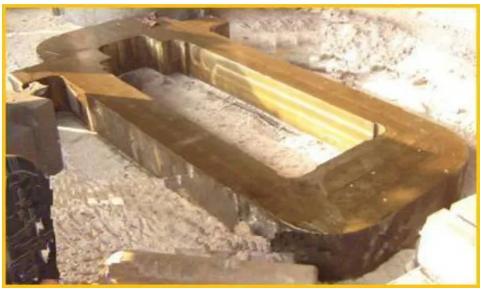
The housing of a work/backup roll bearing is called a chock. It is mounted on the window of the housing
between the posts with a small clearness in open bearing the chock is usually a U-shaped frame of cast steel .in
small mills when rolling is carried out with fixed pass setting the linings are usually mounted directly in the
chock. In large mills where the roll is adjusted after each pass (blooming, primary, and plate mills), lining in
boxes is mounted in the chocks. The lower roll chock is covered to prevent scale getting into the neck bearing,
and to the lower part of the upper roll chock is fastened a support with an additional lining for holding up the top
roll when the mill is idling. Housings are elements in a rolling mill that enclose and support the chock
assemblies, the adjusting mechanism etc., and retain them in their proper positions. They set the rolls in correct
vertical and horizontal position. Their construction and dimensions have to take into account the sizes of various
other elements. The forces, which act on the rolls during rolling, are completely transferred on to the housing.
So, the housing of rolling stand requires high rigidity, sufficient strength for taking the loads, simplicity of
Fig. 3.1: Forces acting in rolling process
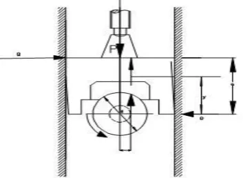
The chock strength can be ascertained approximately allowing for screw-down pressure and the tilting moment
due to friction forces Q from the housing preventing the turning of the chock are
Fig. 3.2: Forces acting on top roll chock support
Q = (P/A)*l
Q= (P/A)* µ* d/2
Where
P = the pressure of the screw down, a = the arm of the couple Q , l = the radius of the circumference of friction
µ = the coefficient of friction, d = the neck diameter,
The greatest bending moment will being the cross section I-I, where the bending stresses are defined by the
formula
= Q y/w
Where,
y= Arm of the forces Q to neutral line of the section under consideration, w= opposing moment of the
section I-I
The estimated stress on the surface of the chock allowing for the specific pressure p on the foot of the screw
down is
Cal = ó +p
The top roll chock support is considered as a beam held at two points. The bending moment acting in the middle
of the support
M=G/4*(l-b/2)
Where,
chocks in three high mills .with the exception of mills havingan adjustable middle roll and three high blooming
mills, are calculated for bending using equations Except that in this case the value of G is equal to the pressure
on the roll neck during rolling, and is equal to the t distance between the chock supports .in view of the limited
size of the middle roll chocks and the large bending moment it is recommended that they should be made of
forged steel with improved mechanical properties.
3.2 Material Used For Chocks
The original Roll Chocks are manufactured by fabricating from cast steel or gray cast iron. The cast iron from
which such Roll Chocks are manufactured should contain carbon from 0.2% to 0.3%. In cast Iron Roll Chocks,
minor welding repair is possible but major welding repair is not possible to these cast iron Roll Chocks because
the major welding repair, large amount of welding material is required.
IV. MATHEMATICAL ANALYSIS OF CHOCK
4.1 Manufacturing Process of Roll Chocks
Roll Chocks can also be made of steel casting but in this manufacturing process a great diligence and utmost
care are required. Especially, during the formation of precision holes of roller bearings and machining of
diameters of these chocks, high degree of accuracy is needed. Surface accuracies of the holes those are present
in these chocks is very essential.
Fig. 4.1: Pressure diagram
4.2 Calculation of Roll Load
The force on the frame is the force applied by the rolls. It can be calculated by the most commonly used
T-selikov theory. The forces on the roll neck and in the housing posts are identical. The strength of the neck (with
a constant relation between its diameter and length) is approximately proportional to d2
Where d= diameter of roll neck bearing.
For various mills, roll load depends on the roll material.
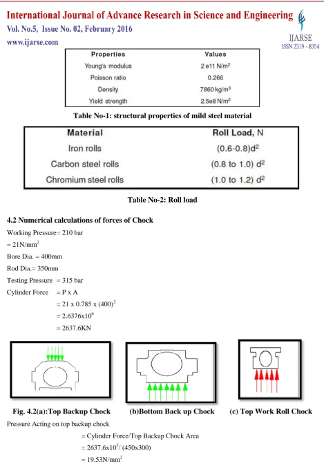
Table No-1: structural properties of mild steel material
Table No-2: Roll load
4.2 Numerical calculations of forces of Chock
Working Pressure = 210 bar
= 21N/mm2
Bore Dia. = 400mm
Rod Dia.= 350mm
Testing Pressure = 315 bar
Cylinder Force = P x A
= 21 x 0.785 x (400)2
= 2.6376x106
= 2637.6KN
Fig. 4.2(a):Top Backup Chock (b)Bottom Back up Chock (c) Top Work Roll Chock
Pressure Acting on top backup chock
= Cylinder Force/Top Backup Chock Area
= 2637.6x103/ (450x300)
= 19.53N/mm2
Pressure Acting on Bottom backup chock
= Cylinder Force/Bottom Backup Chock Area
= 2637.6x103/ (810*405)
Pressure Acting on Top Work roll Chock
= Cylinder Force/Top Work Roll Chock Area
= 2637.6x103/ (550x350)
= 13.7N/mm2
Fig. 4.3: Bottom Work Roll Chock
Pr
essure Acting on Bottom Work roll Chock
= Cylinder Force/Bottom Work Roll Chock Area
=2637.6x103/ (720x350)
=10.4N/mm2
V. CONCLUSIONS
This paperreviewsthe earlier literature, which gives information about chock material and its operating
conditions. The earlier literature only gives the idea about critical areas where the stresses can be induced at
maximum level during the working conditions. From this literature we study that by using Finite Element
Analysis the weight of chock can be reduce without affecting the life cycle of the rolling mill housing. The
rolling chock can be design by applying Computer Aided Design and Engineering method for rolling housing
mill and pressure generated on the surface of chock.
REFERENCES
[1] KatyalPuneet, “Stress analysis and optimization of rolling mill housing using CAE”, Thesis for ME in
.CAD/CAM ,Thapar Institute Of Engineering and Technology (Deemed University),Patiala-147004,
(India)
[2] A.G.Davenport, “The application of statistical concept to the wind loading of structure”,
proc.Inst.CivilEngg. London 19(1961)449-472.
[3] Theodore G. ToRidis, “Computer analysis of rigid frames, Computers”, Volume 1, Issues 1-2, August
1971, Pages 193-221.
[4] William Prager , “Conditions for structural optimality”, Computers & Structures‟, Volume 2, Issues
5-6, 1972, Pages 833-840
[5] J. H. Rong, “An improved method for evolutionary structural optimization against
[6] G. P. Steven, “Multicriteria optimization that minimizes maximum stress and maximizes stiffness”,
Computers & Structures Volume 80, Issues 27-30 , November 2002, Pages 2433-2448.
[7] Rafael Febres, “Modeling of local buckling in tubular steel frames subjected to cyclic Loading”,
Computers & Structures, Volume 81, Issues 22-23, September 2003
[8] Kurt Maute, “an interactive method for the selection of design criteria and the formulation of
optimization problems in computer aided optimal design”, Computers Volume 82, Issue 1 , January
2004, Pages 71-79.
[9] Wen-Da Wanga,b, Lin-HaiHanb, Xiao-Ling Zhao, “Analytical behavior of frames with steel beams to
concrete-filled steel tubular column”, Journal of Constructional Steel Research, Volume 65, year 2009,
Pages 497_508
[10] EsbenLindgaard , Erik Lund, “Nonlinear buckling optimization of composite structures” Computer
Methods in Applied Mechanics and Engineering volume 199, year 2010, Pages 2319–2330.
[11] H. Akbulut, O.Gundogdu,M.S-engul, “Buckling behaviors of laminated composite stepped flat columns”
Finite Elements in Analysis and Design, Volume 46, year 2010, Volume 1061–1067
[12] BojanDolšak , Marina Novak, “Intelligent decision support for structural design analysis”, Advanced
Engineering Informatics volume 25 ,year -2011, pages 330–340
[13] Wei-XinRen, Hua-Bing Chen,“Finite element model updating in structural dynamics by using the
response surface method‟, Engineering Structures Volume 32 year 2011, Pages 2455 -2465
[14] Wen-Yu He, Wei-XinRen, “Finite element analysis of beam structures based on trigonometric wavelet”,
Finite Elements in Analysis and Design, Volume 51, year 2012, Pages 59–66
[15] N. Krauberger, S. Bratina, M. Saje, S. Schnabl, I. Planinc, “Inelastic buckling load of a locally weakened
reinforced concrete column”, Engineering Structures Volume 34, year 2012, Pages 278–288.
Books:-
1. A.I. Tseliko and V.V. Smirnov, M.H.T. Alford (1965), Rolling Mills.
2. William L.Roberts (1938), “Manufacturing engineering and materials processing/2”,
Cold Rolling Of Steel.
3. Ginzburg Vladimir B.”High-Quality Steel Rolling Theory and practice M. Newyork”, USA, Marcel Deker