Power Quality Improvement of Grid
Connected Wind Energy System by
STATCOM-Control Scheme
Shivaraja D M
1, S.Saranya
2PG Student [PSE], Dept. of EEE, AMC Engineering College, Bangalore, Karnataka, India1 Assistant Professor, Dept. of EEE, AMC Engineering College, Bangalore, Karnataka, India2
ABSTRACT:when the wind power is connected to an electrical grid effects of the power quality. The effects of power quality measurements are the active power, reactive power, variation of voltage, flickers, harmonics and electrical behavior of the switching operation. The installation of the wind turbine with grid causes power quality problems determined by studying this paper. For this static compensator (STATCOM) with a battery energy storage system (BESS) at the point of common coupling to mitigate the power quality problems. The grid connected wind energy generation system for the power quality improvement by using STATCOM control scheme is simulated using SIMULINK power system blocked set. This is relives the main supply source from the reactive power demand of the load and induction generator in this proposed scheme. The improvement in the power quality on the grid has been presented here according to the guidelines specified in IEC-61400 standard (International Electro-technical commission) provides some norms and measurements.
KEYWORDS: International Electro-technical commission (IEC), STATCOM, Battery Energy Storage System, (BESS), Total Harmonic Detection (THD), and Point of Common Coupling (PCC)
I. INTRODUCTION
The renewable energy resources like wind, hydro, biomass etc.. Are necessary to sustainable growth and social progress, it is necessary to meet the energy need by utilising the renewable energy resource like wind. The need to integrate the renewable energy like wind energy into power system is to make it possible to minimize the environmental impacts. Power quality is defined as power that enables the equipment to work properly. A power quality problem can be defined as any deviation of magnitude, frequency, or purity from the ideal sinusoidal voltage wave form. Good power quality is benefit to the operation of electrical equipment, but poor power quality will produce great harm to the power system. However, the generated power from wind energy conversion system is always fluctuating due to the nature of the wind. Therefore injection of the wind power into an electric grid affects the power quality. The important factors to be considered in power quality measurements are the active power, reactive power, variation of voltage, flicker, harmonics, and electrical behaviour of switching operation. In this proposed scheme static synchronous compensator (STATCOM) is connected at a point of common coupling with a battery energy storage system (BESS) to mitigate the power quality issues. Therefore STATCOM provides reactive power support to wind generator and load. The battery energy generation system for power quality improvement is simulated using MATLAB/SIMULINK in power system block set .In the surveying of the stating supplying power (voltage/current) including the harmonics percentage is more while concluding in the ending stage of the output power (voltage/current) Is increased and harmonics percentage is reduced finally we get power quality improved.
OBJECTIVE OF THE PAPER
The grid connected wind energy generation system for power quality improvement by using STATCOM has the following objectives.
To Maintains power factor as unity at the source end.
II. STATCOM-STATIC SYNCHRONOUS COMPENSATOR
The STATCOM is a shunt-connected reactive power compensation device that is capable of generating and/or absorbing reactive power and in which the output can be varied to control the specific parameter of an electric power system. It is in general a solid-state switching converter capable of generating or absorbing independently controller real and reactive power at its output terminals when it is fed from an energy source or energy-storage device at its input terminals. Specifically, the STATCOM considered in this chapter is a voltage-source converter that, from a given input of dc voltage, produce a set of 3-phase ac-output voltage, each in phase with coupled to the corresponding ac system voltage through a relatively small reactance (which is provided by either an interface reactor or the leakage inductance of a coupling transformer)
The dc voltage is provided by an energy-storage capacitor.
The power-oscillation damping in power transmission systems.
The dynamic voltage control in transmission and distribution systems.
The transient stability.
The voltage flicker control.
Fig.1.System operational scheme in grid system
III. SYSTEM OPERATION
The shunt connected STATCOM with battery energy storage is connected with the interface of the induction generator and non-linear load at the PCC in the grid system. The STATCOM compensator output is varied according to the controlled strategy, so as to maintain the power quality norms in the grid system. The current control strategy is included in the control scheme that defines the functional operation of the STATCOM compensator in the power system. A single STATCOM using insulated gate bipolar transistor is proposed to have a reactive power support, to the induction generator and to the non-linear load in the grid system. The main block diagram of the system operational scheme is shown in fig.2.
IV. CONTROL SCHEME
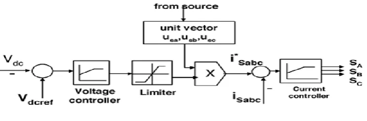
The control scheme approach is based on injecting the currents into the grid using “hysteresis current controller”, using this technique, the hysteresis current controller keeps the control system variable between boundaries of hysteresis area and gives correct switching signals for STATCOM operation. The control algorithms need the measurements of several variable such as three-phase source current (iabc), DC voltage (Vdc), inverter current (iabc).
The current control block, receives an input of reference current (i*abc) and actual current (iabc)are subtracted so as to activate the operation of STATCOM is presented below. The RMS voltage source amplitude is calculated at the sampling frequency from the source phase voltage (Va, Vb, Vc) for the three phase balanced system. And this can be expressed as Vm, sampled peak voltage, is in below equation.
Vsm = {(2/3)(Vsa 2
+Vsb 2
+Vsc 2
Fig.2.control scheme
The in-phase unit vector are obtained from AC source phase voltage and the RMS value of unit vector are shown below as
usa = (Vsa/Vsm); usb = (Vsb/Vsm); usc = (Vsc/Vsm)---2
The in-phase generated reference current are derived using in-phase unit voltage templates as represented below as
i*sa=I.usa ; i*sb=I.usb; i*sc=I.usc---3
Where I is proportional to the magnitude of filtered source voltage for respective phases .This ensure that the source current is controlled to be sinusoidal. The unit vectors implement the important function in the grid connection for the synchronization for STATCOM
The reference current is generated as in equation below and actual current are detected by current sensor and are subtracted for obtaining a current error for a hysteresis based current controller. Thus the ON/OFF switching signals for IGBT of STATCOM are derived from hysteresis controller. The switching function SA for phase „a‟IS EXPRESSED AS
When Ia< (I*a-HB), SA=0 When Ia > (I*b-HB),SA=1
Where HB is a hysteresis current-band, similarly the switching function SB, SC can be derived for phases b and c respectively
V. SYSTEM PERFORMANCE
The proposed control scheme is simulated using SIMULINK in power system block set. The system parameter for given system is given Table I. The system performance of proposed system under dynamic condition is also presented.
Voltage Source Current Control—Inverter Operation
The three phase injected current into the grid from STATCOM will cancel out the distortion caused by the non-linear load and wind generator .The IGBT based three-phase inverter is connected to grid through the transformer. The generator of switching signals from reference current is simulated within hysteresis band of 0.08. The choice of narrow hysteresis band switching in the system improves the current quality and control signal of switching frequency within its operating band.
Table I: System Parameters
Sl.No Parameters Ratings 1. Grid Voltage 3-phase, 415V, 50Hz 2. Induction Generator 3.35KVA, 415V, 50Hz, P=4
Rs=0.01Ω, Rr=0.015Ω, Ls=0.06H, Lr=0.06H
4. IGBT Rating Collector Voltage = 1200V Forward Current = 50A Gate Voltage = 20V Power Dissipation = 310W 5. Load parameter Non-linear Load = 25Kw
6 Line series inductance 0.05 Mh
STATCOM—Performance under Load Variations
The wind energy generating system is connected with grid having the non-linear load. The performance of the system is measured by switching the STATCOM at time t=0.7s in the system and how the STATCOM responds to the step change command for increase in additional load at 1.0 s is shown in the simulation. When STATCOM controller is made ON , without change in any other load condition parameter, it starts to mitigate for reactive demand as well as harmonic current. This additional demand is fulfil by STATCOM compensator. The simulation proposed control scheme with STATCOM is shown in fig.3. The output of STATCOM is shown in fig.4.The DC link voltage regulates the source current in the grid system, so the DC link voltage is maintained constant across the capacitor. The source current waveform in simulated model is analysed with STATCOM and without STATCOM operation.The below test with proposed scheme has not only power quality improvement feature but it also has sustain capability to support the load with the energy storage through the batteries. The DC link voltage and current through capacitor are shown in fig.5.The source voltage and current at PCC is shown in Fig.6.
VI.SIMULATION AND RESULTS
Fig.3.proposed control scheme with STATCOM
It is observed that the source current on the grid is affected due to the effects of nonlinear load and wind generator. Thus purity of waveform may be lost on the both sides in the system. The inverter output voltage under STATCOM operation with load variation is shown in fig.4
Fig.5.DC Link voltage and current through capacitor
The DC link voltage regulates the source current in the grid system,so the DC link voltage is maintained constant across the capacitor shown(upper).The current through the dc link capacitor indicating the charging and discharging operation as shown(lower) in Fig.5
Fig.6. (a) source current, (b) load current,(c) inverter injected current, (d)wind generator current
The wind energy generating system is connected with grid having the nonlinear load. The performance of the system is measured by switching the STATCOM at time t=0.7s in the system and how the STATCOM responds to the step change command for increase in additional load at 1.0s is shown in the simulation. When STATCOM controller is made ON, without change in any other load condition parameters, it starts to mitigate for reactive demand as well as harmonic current. The dynamic performance is also carried out by step change in a load, when applied at 1.0s. This additional demand is fulfill by STATCOM compensator. Thus, STATCOM can regulate the available real power from source. The result of source current, load current are shown in Fig.(a) and (b) respectively. While the result of injected current from STATCOM are shown in Fig.6(c) and the generated current from wind generator at PCC(Point of Common Coupling)are depicted in Fig.6(d).
The Fourier analysis of this wave form is expressed and the THD of this source current at PCC without STATCOM is 4.06% as shown in Fig.7.
Fig.8.FFT analysis with controller (THD=0.48%)
The power quality improvement is observed at point of common coupling, when the controller is in ON condition. The STATCOM is placed in the operation at 0.7s and source current at PCC with STATCOM is 0.48% and waveform is shown in fig.8.with it‟s FFT. It is shown that the THD has been improved considerably and within the norms of the standard.
VI. CONCLUSION
This paper presents the grid connected wind energy system for power quality improvement by using STATCOM. The power quality problem, its consequences and their mitigating techniques are presented here. In this proposed scheme to eliminate the harmonic content of the load current the STATCOM-BESS control system is used. So that power quality is maintained at the point of common coupling. And hysteresis current control scheme in the STATCOM is used for the fast dynamic response. It also Maintain voltage and current in phase. That means unity power factor is maintained at the source end.
REFERENCES
[1] Sharad W.Mohod and Mohan V.Aware “A STATCOM-Control scheme for grid connected wind energy system for power quality improvement” IEEE systems journal vol.4 sept-2010
[2] A. Sannino, “Global power systems for sustainable development,” in IEEE General Meeting, Denver, CO, Jun. 2004.
[3] K. S. Hook, Y. Liu, and S. Atcitty, “Mitigation of the wind generation integration related power quality issues by energy storage,” EPQU J., vol. XII, no. 2, 2006.
[4] R. Billinton and Y. Gao, “Energy conversion system models for adequacy assessment of generating systems incorporating wind energy,” IEEE Trans. on E. Conv., vol. 23, no. 1, pp. 163–169, 2008, Multistate.
[5] C. Han, A. Q. Huang, M. Baran, S. Bhattacharya, and W. Litzenberger, “STATCOM impact study on the integration of a large wind farm into a weak loop power system,” IEEE Trans. Energy Conv., vol. 23, no. 1, pp. 226–232, Mar. 2008.
[6]R. S. Bhatia, S. P. Jain, D. K. Jain, and B. Singh, “Battery energy storage system for power conditioning of renewable energy sources, ”in Proc. Int. Conf. Power Electron Drives System, Jan. 2006, vol. 1, pp.501–506.
BIOGRAPHY
Shivaraja D M received the B.E. degree in Electrical and Electronics Engineering in 2013 from RITM, Bangalore and doing M.Tech degree in Power System Engineering from AMC Engineering College, Bangalore.