Experimental and numerical study of a bird strike against a windshield
Fabien Plassarda, Pierre-Louis Hereil, Pierric Joseph, and J´erˆome Mespoulet THIOT INGENIERIE, Route Nationale, 46130 Puybrun, France
Abstract. This paper describes a bird strike study performed at THIOT-INGENIERIE laboratory. For aeronautic requirements, the 220 mm version of the gas gun TITAN is used to perform bird strike on instrumented structures. This paper shows a bird strike on a polycarbonate windshield instrumented with high speed cameras, velocity and force sensors. A crossed work with numerical simulation has been performed to design target support and diagnostic tools. It permits also to demonstrate reliability of the numerical tools.
1. Introduction
Since the beginning of the aeronautic age, around 250 deaths and 80 destroyed civil aircrafts have been caused by bird strikes [1]. Moreover, with the increase of the traffic, the cost of bird strike damages and delays is higher than 1 billion dollars in the world. Civil Aircraft in the United States reported 30 bird strikes per day in 2013 [2,3]. The vulnerable parts of planes or helicopters are windshield, nose, fuselage panels, wing and empennage leading edges, rotor blades, fan blades and engines inlets (Fig. 1). Bird strike resistance has to be proved for the dynamic certification tests. During the design of aeronautic parts, numerical simulations allow studying the best technical solution to get the best structural behaviors.
A simultaneous work between experiments and numerical simulations is necessary to well understand the behavior of a bird during an impact and also the reaction of the impacted material and structure.
This paper deals with the study of a bird strike against a windshield performed at THIOT-INGENIERIE shock physics laboratory.
The first part presents the experimental configuration and the metrology of the test and the second part shows the associated numerical simulation performed to anticipate and fit the results.
2. Experimental setup
The TITAN Light Gas Gun (LGG) is a single stage launcher (Fig.2) which can be configured using different barrel diameters: Ø60 mm, Ø100 mm, Ø 220 mm and Ø 350 mm [4–6]. Thanks to this particularity, this LGG allows to obtain several impact velocities with numerous types of projectiles or targets. For each TITAN LGG configuration, the projectile velocity achievable with a particular projectile weight is summarized on Fig.3.
The objective of the experimental configuration is to launch a 622 g bird at a velocity of 125 m/s on a polycarbonate plate which is representative of a aCorresponding author:technique@thiot-ingenierie.com
Figure 1. Aircraft component exposed to bird strike.
Figure 2. TITAN light gas gun with 220 mm calibre.
Figure 3. Projectile velocities achievable for each configuration
of the TITAN LGG.
windshield. A schematic description of the experimental set-up is presented on Fig. 4. The windshield was positioned on a dedicated tool which provides both angular positioning and suitable impact location. Target positioning was realized using a laser alignment.
Figure 4. Schematic description of the experimental setup.
Figure 5. 3D view of the dedicated tool used to position the test
parts (top) – Gas gun exit and windshield target (bottom).
Laser barriers are used for impact velocity measure-ment and displacemeasure-ment sensors, load sensors and high speed cameras are used to analyse the behaviour of the projectile and the target during impact.
The impactor is a whole dead chicken wrapped with adhesive tape. It is enclosed in a sabot that is designed to carry it at the right location on the windshield target. The total weight of the impactor is 622 g.
The target is a 1046 mm×826 mm polycarbonate plate of 8 mm in thickness. It is screwed on the tool in order to avoid the lateral displacement and to have a well-known condition at the periphery of the plate.
Photographs of the windshield target and the bird projectile are presented on Fig.5and Fig.6.
2.1. Dynamic load sensors
Four dynamic load sensors were positioned at the four corners of the windshield (green arrows on Fig.4). Table 1 summarizes actual precision observed on each load sensor with the full measuring system. Figure 7 indicates sign convention for load measurements.
Figure 6. Alive bird (on the left) - Wrapped dead bird before test
(right).
Figure 7. Sign convention for displacement and load
measure-ments.
Table 1. Precision of CFW/330kN sensors with the full
measuring system.
Sensor number Precision (%)
F1 0.04
F2 0.01
F3 0.08
F4 0.02
Table 2. High speed video cameras settings.
Camera Frames
ID Optics per sec Resolution
Photon Lens 17–35 mm, 6000 512×512 Ultima APX diaphragm 2.8
Phantom Lens 24–70 mm, 6000 1280×800 v710 diaphragm 2.8
Phantom Lens 17–35 mm, 6000 832×544 M320S diaphragm 2.8
2.2. Velocity sensor
The displacement of the windshield was measured using a heterodyne velocimetry system (PDV). This kind of system measures the local velocity of the windshield wall at the impact point through Doppler Effect. Displacement is then calculated using this measure of velocity. Typical error is 1% in the – 2000 m.s−1 / + 2000 m.s−1 range. Bandwidth of this system is estimated to 31 MHz. Sign convention for displacement measurement is indicated on Fig.7.
2.3. High speed cameras
Three high speed video cameras were used during tests: • Photron ULTIMA APX,
• Phantom v710, • Phantom M320S
Figure 8. Schematic description of the cameras locations during
tests (top – side view; bottom – front view).
3. Experimental results
Experimental results obtained during this bird strike test #TI0849 are indicated on Fig. 9 to Fig. 14. Measured projectile velocity is 128±2 m/s.
Photographs of windshield after the test (Fig. 9) indicates:
• no break of the polycarbonate plate and no visible residual strains: the material remained elastic during the impact,
Figure 9. Windshield after test.
Figure 10. Pictures taken from high speed camera #1 (top view).
Figure 11. Pictures taken from high speed camera #3 (lateral
view).
• strong residual strains on the washers of the screws (Red arrows on Fig.9).
Pictures taken from the three high speed cameras (Fig.10, Fig. 11and Fig. 12) indicate some white parts corresponding to the sabot debris but the mass of this pieces made of light foam has no effect.
The bird impacts the center of windshield. It is totally smashed, but it is more consistent than water.
Figure 13. Velocity measurement.
Figure 14. Force measurement (only values between±13 kN are recorded).
PDV measurement behind the windshield shows a maximum velocity of 50 m/s and by time integration, a maximum deflection of 45 mm (Fig.13).
For this test, a mistake has been done on the parameters of the load sensors which results in a saturation of this sensors at a value of±13 KN (Fig.14).
4. Numerical simulations
4.1. Model
Simulations of test #TI0849 have been done using the nonlinear explicit code LS-DYNA. Experimental results are compared to numerical results given by 3D lagrangian elements and 3D-SPH. The SPH solver was firstly introduced in the late 70’s for astrophysics. It is a Lagrangian method with a variable nodal connectivity. It is gridless and thus can handle severe distortions without grid tangling and so does not need the use of unphysical erosion algorithms. This technique is then well adapted for bird strike simulations.
Some studies have been performed to determine what is the right shape to represent a bird in simulations [7]. The choice of using SPH formulation to model the bird allows us to use a more complex shape closer than the shape of a real bird (Fig.15).
Figure 16. Numerical model side view.
Figure 17. Isometric closed views of the mesh.
An homogeneous material model with a low yield strength has been used to simulate the bird. This allows keeping the consistency during the impact. In our case, local behaviors are not preponderant because no local break of the windshield appears and no cutting of the bird occurs: it is why this material model is sophisticated enough for our case study [8].
The entire structure holding the windshield has been modeled with a millimeter sized mesh (Fig.16, Fig.17). The force sensors are set between the windshield holder and the inclined rigid frame. During the dynamic impact, mass and rigidity of each part are essential to reproduce load measurements.
The 46 screws are modeled without prestresses. This unstressed assumption makes possible the observation of the minimal needed tension in the screw during the impact.
4.2. Results and perspectives
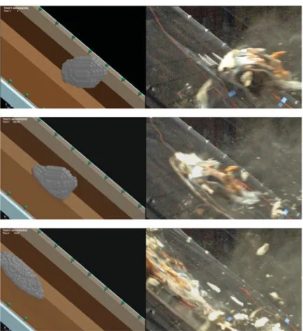
Comparisons between simulation and the three high speed video cameras pictures are indicated on Fig. 18 and Fig.19. These comparisons shows that the global dynamic responses of the bird impactor and the polycarbonate target are correlated. In particular, visible waves of the polycarbonate plate on the middle and between screws are well represented.
Figure 18. Simulation compared with pictures from camera #3.
Figure 19. Simulation compared with pictures from camera #1.
between displacement profiles (obtained by integration of velocity profiles) is very good.
Figure21shows correlation for the load measurement on one corner. For values below 13 kN, level and global shape of the curve are well reproduced. Simulation shows the maximal load expected on each corner is 40 kN and that one screw can have a maximal tension of 14 KN. This value is high enough to explain the distorsion of the washers observed after the test.
Figure 20. Correlation between test and calculation of the
velocity measurement and displacement.
Figure 21. Correlation between test and calculation of load
measurements (one corner).
All these comparisons show that there is a good fitting between experiment and calculation.
This study has shown that the simulation is refined enough (mesh size, material models . . . ) to represent a bird strike on a polycarbonate windshield. It is possible to foresee the behavior of the windshield and design the fastenings.
The limits of this model are:
• A material subjected to local brittle breaks due to reaction to Hugoniot pressure cannot be represented with this material model [9].
• The validity of bird material model is not proved for situation where the bird is cut. Especially for local breaks on turbo fans during motor ingestion or on leading edge. A heterogeneous model in this case may be needed and should be a mandatory [10].
5. Conclusions and future works
TITAN gas gun using the 220 mm caliber has shown its ability to perform bird strike impacts in the big cubic target chamber to work with large instrumented aeronautics structures.
A crossed work between experiments and calculations has been performed to developed test facilities and numerical tools for bird strike studies.
sufficient for every bird strike cases especially for turbo fan ingestion.
References
[1] J. Thorpe: International bird strike committee: “Fatalities and destroyed civil aircraft due to bird strike, 1912-2002 (2003)
[2] Report of Associate Administrator of Airports, Office of Airport Safety and Standards, Airport Safety & Certification “Wildlife strikes to civil aircraft in the United States 1990-2013”, Washington (2014) [3] J.R. Allan, The costs of bird strikes and bird strike
prevention (2000)
(2009)
[6] P. Thiot, Description of a new 220 mm gas launcher at THIOT INGENIERIE’s plant and first results, Proceeding of the 61stARA meeting, Thun (2010) [7] S.C. McCallum, C. Constantinou, The Influence of
Bird Strike Analysis (2005)
[8] L. Jun, L. Yulong, G. Xiaosheng, The Influence of bird-strike on sidewall structure on an aircraft nose, Chin. Soc. Of Aero. & Astro., Beihang University [9] L.S. Nizampatnam, Models and methods for bird
strike load prediction, Aero. Eng. Wikita State University (2009)