HVOF Sprayed Coating’s (WC-Co Ni Cr Si )
to Conduct the Erosion Test
Navinesh.BC1, Prathap.D2, Praveen.D2, Sanjay.S2, Veerendra Patel2, Dr.B.Somasundaram3
Department of Mechanical Engineering, SKIT, School of Mechanical, REVA University Bangalore, India
ABSTRACT: It is a well-known fact that materials that consist of both brittle and ductile constituents can show erosion behavior in either a ductile or a brittle manner. The high velocity oxy-fuel(HVOF) sprayed WC-CoNiCrSi coatings on GrA1 boiler tube steal exhibit composite ductile and brittle modes of erosion under angular silica sand erodent of size 125-180 impacted at 40m/s. The HVOF spraying leads to a high retention of WC in the coating matrix accompanied with lower porosity. The as-sprayed as well as eroded coatings have been characterized using scanning electron microscope and optical profilometer.
KEYWORDS: HVOF process, erosion test, coating composition, and 306-SS
I. INRODUCTION
Erosive wear is caused in the solid bodies by the action of sliding or impact of solids, liquids, gases or a combination of these [1]. Manifestations of solid particle erosion in service usually include thinning of components, a macroscopic scooping appearance following the gas particle flow field, surface roughening, lack of the directional grooving characteristic of abrasion and in some but not all cases, the formation of ripple patterns on metals [2]. Solid particle erosion is an important material degradation mechanism encountered in a number of engineering systems such as thermal power plants, aircraft gas turbine engines, pneumatic bulk transport systems, coal liquefaction/gasification plants and ore or coal slurry pipe lines [3,4].
Power plants are one of the major industries suffering from severe corrosion and erosion problems resulting in the substantial losses. Erosion results from impact of particulates, such as coal ash, dolomite and unburned carbon particles o the surface of heated boiler tubes. It is generally believed that the most erosive species in the fly ash are quartz, which is a crystalline from of SiO2 and mullite. More than one quarter of all the boiler tube failures worldwide are caused by fly ash erosion [5,6].
Fig 1.1 Erosion on Metal Surface
overly, diffusion coating, thermal spraying and laser cladding. The most important drawbacks diffusing coatings are that they are thin and cannot be produced on sight or repaired. In compression with diffusion coatings, thermal spray coatings do not require such a high temperature of the base metal that would impair the mechanical or micro structural properties in the case of weld overly there is increase in corner that repeated weld overlay application to the same tube area may result in embrittlement of the old overlay and lead to cracks that could propagates in to the overlaid tube. Because of the mentioned short coming in diffusion and weld overlay coatings, attention is increasingly being forced on thermal sprayed coating.[1],[2],[3],[4],[5],[10].
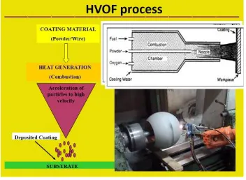
II. HIGH VELOCITY OXY-FUEL PROCESS (HVOF) 2.1. Explanation on HVOF Process
Fig 2.1 Block Diagram of HVOF Process.
HVOF is a method of propelling molten particles on to work surfaces for each coating. As an essential feature of thermal spray coatings, sprayed particles – upon and after impact – deform so as to interlock with the impact surface’s profile. While the initial thermal spray technology focused on guaranteed deformation through excessive heating, a new method is introduced with the high velocity of HVOF.
A small chamber is used to create supersonic velocity of exhaust. The focused exhaust stream receives the powder material at a velocity that the resultant impact forges adequate bonding. In fact, the impact from the kinetic energy is so great that most of the porosity is eliminated. As such, the less porous coating provides the best wear resistance and densest coatings available. The HVOF thermal spray process uses the combustion gases such as propane, propylene hydrogen or a liquid fuel such as a kerosene fuel and oxygen.[1],[2],[3],[5]
2.2. HVOF Process Parameters
Oxygen flow rate 200 l/mm
Fuel (LPG) flow rate 50 l/mm
Air flow rate 750 l/mm
Spray distance 100mm
Powder feed rate 36g/min
2.2. Coating Compositions
In this coating, 80% of coating contains WC Co and 20% of Ni Cr Fe Si.
The percentage of WC - 66.4, Co - 13.6, Ni - 8.67, Cr- 9.82, and that of Si - 1.557.
III. EXPERIMENTAL PROCEDURE 3.1 Substrate material and development of coating
Low carbon steel ASTM-SA201 grade A1(GrA1) which is used as material for boiler tubes in some coal fired thermal power plants in northern part of India has been used as substrate in the study. The specimens with approximate dimensions of 30mm*30mm*5mm were cut from the tubes for erosion studies. Samples were grinded with SiC papers down to 180 grit and grit blasted with Al2O3 (grit45) before being HVOF sprayed to develop better adhesion between the subtract and the coating. [8],[9],[10]
The composite coating powder of 80%WC CO-NiCrFeSi was used to spray to deposit coatings using HVOF Process.
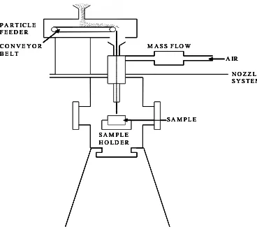
3.2 Erosion Test Equipment and Setup
Fig 3.1 Block Diagram of Erosion Test Equipment Fig 3.2 Air Jet Erosion Test Machine
P A R T I C L E F E E D E R C O N V E Y O R B E L T
M A S S F L O W
A IR N O Z Z L E S Y S T E M
S A M P L E S A M P L E
H O L D E R P A R T I C L E
F E E D E R C O N V E Y O R B E L T
M A S S F L O W
A IR N O Z Z L E S Y S T E M
S A M P L E S A M P L E
H O L D E R P A R T I C L E
F E E D E R C O N V E Y O R B E L T
M A S S F L O W
A IR N O Z Z L E S Y S T E M
S A M P L E S A M P L E
H O L D E R P A R T I C L E
F E E D E R C O N V E Y O R B E L T
M A S S F L O W
A IR N O Z Z L E S Y S T E M
S A M P L E S A M P L E
H O L D E R
Air pressure
Model no of the gun
Diameter of the gun
535kpa
5220
11mm
WC Co Ni Cr Si
Erosion Test Procedure:
• Before conducting the test, the specimen surface was cleaned properly.
• The sample is clamped at the fixture. The required angle and standoff distance was adjusted.
• The air at required pressure is mixed with the erosive particle and is directed to a specimen for specified time duration.
• The initial mass and the mass of the specimen after erosion were found out using the weighing machine. • The above steps are repeated for different parameters mentioned.
3.3 Erosion Test for Substrate (306-SS)
Its compositions are listed below:
Element Percent by Weight 306-SS
Carbon 0.08
Manganese 2.00
Silicon 0.75
Chromium 16.00
18.00
Nickel 10.00
14.00
Molybdenum 2.00
3.00
Phosphorus 0.045
Sulfur 0.030
Nitrogen 0.10
Iron Bal.
1.6 Tables for Impingement Angles (300, 600, 900) 300Table
Fig 4.1 Erosion Test for 300
Cycle Initial Final
5 15.6445 15.6440
10 15.6440 15.6395
15 15.6395 15.6393
20 15.6393 15.6392
600 Table
Fig 4.2 Erosion Test for 60
900Table
Fig 4.3 Erosion Test for 900
3.4 Erosion Test for Coating Components (300, 600, 900)
Coating Compositions – WC Co-NiCrSi (80%-20%) 300 Table
Fig 4.4 Erosion Test at 300
600 Table
Fig 4.5 Erosion Test at 600
Cycle Initial Final
5 19.6329 19.6326
10 19.6326 19.6324
15 19.6324 19.6323
20 19.6323 19.6323
Cycle Initial Final
5 19.6335 19.6332
10 19.6332 19.6330 15 19.6330 19.6329
20 19.6329 19.6329
Cycle Initial Final
5 16.2802 16.2773
10 16.2773 16.2760
15 16.2760 16.2743
20 16.2743 16.2736
25 16.2736 16.2730
30 16.2730 16.2730
Cycle Initial Final 5 21.2661 21.2652 10 21.2652 21.2633
15 21.2633 21.2617 20 21.2617 21.261
900 Table
Fig 4.6 Erosion Test at 900
IV. RESULT AND DISCUSSION
4.1 Comparison Between Substrate and Coating
4.1.1 Graph for Coating and Substrate at 300, 600 and 900
Explanation: From the above graph the erosion rate increased in coating compared to substrate at 600and 900
Explanation: Bar Graph shows the erosion rate of Substrate and Coated materials
V. CONCLUSION
High velocity oxy-fuel thermal spraying with oxygen and liquid petroleum gas as fuel gases has been used successfully to deposit WC Co-NiCrSi alloy coatings on boiler tube steels. LPG fuel gaze is cheap and readily available as compared to other fuels used for HVOF spraying. Under the given spray parameters coating with average thickness 290microns and average porosity of 0.5%has been achieved coating deposited resulted in hardness value of 1223HV.
WC Co- NiCrAlYSi coatings show retention of higher amount of WC in matrix with a minor amount of W2C brittle phase.
The erosion resistance of WC Co- NiCrSi coating maybe attributed to composite ductile and brittle modes of material removal although brittle mode is dominant. The morphology of the eroded surface points out craters.
15 20 25
Line Graph for …
5 10 15
20 25 30
15 20 25
Substrate Coating
Line Graph for 90
05 10 15
20 25 30
15 20 25
Substrate Coating
Line Graph for 60
05 10 15
20 25 30
Cycle Initial Final
5 21.2723 21.2707 10 21.2707 21.2696 15 21.2696 21.2689
20 21.2689 21.2668
25 21.2668 21.2661
30 21.2661 21.2661
0 50
30 60 90
Bar Graph for Substare and Coated
Substrate steel exhibit slower steady state volume erosion rate in comparison to HVOF sprayed WC Co- NiCrSi coatings under similar test conditions. The higher hardness ratio between silicon erodent particle and substrate steel might have caused the penetration of silica particles into the surface.
Erosion rate with respect to angle of impact is maximum at 30degree and minimum at 90degree. Erosion rate with respect to stand of distance is maximum at 100mm and lower for 200mm. This implies that lower the stand of distance greater is the rate of erosion.
Erosion rate with respect to Pressure increases as the rate of erosion increases.
From the predicted mechanism it is found that the erosion behavior is valid for ductile materials. Hence our observation also follows the same rule.
Having calculated the ideal angle of contact, force of impingement and the distance of fall for a Mild Steel, Aluminum, Stainless Steel, we would now be in a position to predict the condition that should be maintained to minimize wear.
REFERENCES
1. P.H.Shipway, The potential of WC-Co hardness and HVOF sprayed coatings to combat water droplet erosion, www.elsevier.com, Wear 271(2011) 1418-1425.
2. L.Thakur, A comparative study on slurry and dry erosion behaviour of HVOF sprayed WC-CoCr coatings, www.elsevier.com,Wear 303(2013) 405-411.
3. Guoliang Hou, Cavitation erosion of several oxy-fuel sprayed coatings tested in deionized water and artificial seawater, www.elsevier.com,Wear 311(2014) 81-92.
4. J.R.Laguna-Camacho, solid particle erosion behaviour of TiN coating on AiSi 4140 steel, journal of surface engineered materials and advanced technology,(2014), 4, 1-8.
5. M.S.Mahdipoor, HVOF sprayed coatings of nano-agglomerated tungsten-carbide powders for water droplet erosion application, www.elsevier.com, Wear 330-331(2015) 338-347.
6. Yan Wang, Cavitation erosion of plasma-sprayed CoMoCrSi coatings, www.elsevier.com, Tribology international 102(2016)429-435. 7. Gabriel Taillon, Cavitation erosion mechanisms in stainless steel and in composite metal-ceramic HVOF coatings, www.elsevier.com, Wear
364-365(2016) 201-210.
8. A.K.Krella, Cavitation erosion of CrN/CrCN multiplayer coating, www.elsevier.com, Wear 386-387(2017) 80-89.
9. Chuhong Wang, Indentation and erosion behaviour of electroless Ni-P coating on pipeline steel, www.elsevier.com, Wear 376-377(2017) 1630-1639.
10. G.V. Kachalin, Experimental research results of solid particle erosion resistance of blade steel with protective coating, Journal of physics:conf.series 891 (2017) 12259.
11. Hongwei Zhang, solid particle erosion-wear behaviour of Cr3 C2 –NiCr coating on Ni-based super alloy, Advances in mechanical engineering, (2017) vol. 9(3) 1-9.
12. Kumar R.K, A pragmatic approach and quantitative assessment of slit erosion characteristics of HVOF and HVAF processed WC-CoCr coatings, www.elsevier.com, Material and Design 132(2017) 79-95.
13. L.Venkatesh, Microstructural response of various chromium carbide based coatings to erosion and nano impact testing, www.elsevier.com,Wear 386-387 (2017) 72-79.
14. M.A.Gonzalez, Study of the erosion wear behaviour of cryogenically and tempered WC-CoCr coating deposited by HVOF, www.elsevier.com, Wear 376-377 (2017) 595-607.
15. Miguel angle Reyes Mojena, Neural network analysis for erosive wear of hard coatings deposited by thermal spray: Influence of microstructure and mechanical properties, www.elsevier.com, Wear 376-377 (2017) 557-565.