ISSN(Online): 2320-9801 ISSN (Print): 2320-9798
I
nternational
J
ournal of
I
nnovative
R
esearch in
C
omputer
and
C
ommunication
E
ngineering
(An ISO 3297: 2007 Certified Organization)
Vol. 3, Issue 2, February 2015
Performance Analysis and Comparison of
Square and Rectangular Antenna Embedded
With Same DGS
Vidyadhar S Melkeri1* P V Hunagund2 S L Mallikarjun3
School of Engineering, Central University of Karnataka, Kalaburagi, India1
Department of Applied Electronics Gulbarga University Kalaburagi, India 2, 3
ABSTRACT: The achievement of high data-rates and low signal power the Research and Development of Microwave engineering has been focusing to overcome some of the disadvantages. From the review of literature it’s found that defected ground structure may meet the demands and has been rarely used in the improvement of antenna parameters. Intentionally created error or the slot in the ground plane of a microstrip antenna is referred as the Defected Ground Structure (DGS) and is used for different applications. DGS open field of development in the fields of microwave engineering which leads to thousands of applications and developments till date.
In this paper microstrip patch antennas both rectangular and square are designed for 2.4GHz frequency. For the antenna miniaturization and better bandwidth improvement H-shaped DGS on MSA is used. The simulation process has been done through Finite Element Machine (FEM) based software High Frequency Structure Simulator (HFSS) software. The properties of antennas such as reflection co-efficient, bandwidth and gain are determined and compared with each other. The reflection coefficient of square patch antenna is -6dB better than that of rectangular patch. The bandwidth of square patch is found to be 2.4% i.e. 40MHz whereas for rectangular patch it is 1.7% i.e. 30MHz. The radiation pattern of both antennas is remaining unchanged. Further it is observed that the performance of square patch antenna is better than rectangular patch after embedded with H-shaped defect ground structure. Proposed antenna may find its application in wireless LAN protocols such as Bluetooth, IEEE 802.11 and in 2.4GHz ISM Band.
KEYWORDS: Antenna, Rectangular MSA, Square MSA, DGS, Bandwidth.
I. INTRODUCTION
Defected Ground Structure, as the name reflects it’s the deliberately created mistake in the ground plane of microstrip antenna, which is of particular geometry and shape which is etched out as a single defect or periodic configuration to create a feature of stopping wave propagation through the substrate over a frequency range. Hence DGS can be defined as a unit cell EBG [1]. The DGS slots are resonant in nature. Conventionally, in planar microstrip circuits, a DGS is located beneath a microstrip line and it perturbs the electromagnetic fields around the defect. Trapped electric fields give rise to the capacitive effect (C), while the surface currents around a defect cause an inductive effect (L). This, in turn, results in resonant characteristics of a DGS They have different shapes and size with different frequency responses and equivalent circuit parameters. The presence of DGS under the printed transmission line actually perturbs the current distribution in ground plane and thus modifies the equivalent line parameter over the defected region. Thus it influences the guided wave characteristics and exhibits
1. Band-gap properties as revealed due to EBG structure.
2. A slow wave effect, which helps in compacting, printed antenna circuit.
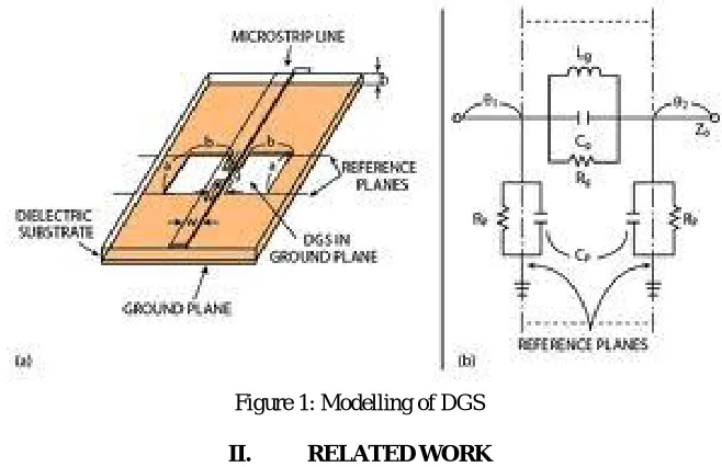
Modelling of DGS
ISSN(Online): 2320-9801 ISSN (Print): 2320-9798
I
nternational
J
ournal of
I
nnovative
R
esearch in
C
omputer
and
C
ommunication
E
ngineering
(An ISO 3297: 2007 Certified Organization)
Vol. 3, Issue 2, February 2015
in the ground plane of microstrip line, giving rise to equivalent inductance and capacitance. Thus DGS behaves like L-C resonator circuit coupled to microstrip line.
When an RF signal is transmitted through a DGS- integrated microstrip line, strong coupling occurs between the line and the DGS around the frequency where DGS resonates. If the transmitted signal covers the resonant frequency of DGS, and most of the signal is stored in its equivalent parallel LC resonator. Basically modelling is classified into three main categories: (a) transmission line modelling [8]; (b) LC and RLC circuit modelling [9]; and (c) quasi-static modelling [10].
Figure 1: Modelling of DGS
II. RELATED WORK
The structure having periodic arrangement of metallic, dielectric or metallodielectric bodies with lattice period p=n /2, being the guide wavelength, are found to exhibit EBG behavior. Their productivity may be broadly classified into three groups: (1) Three dimensional (3D) [7]; Two-dimensional (2D) [8]; One-dimensional (1D) [9]; Depending on configurations and size it is classified into Unit cell and Periodic, Unit cell DGS have different shapes and sizes according to the requirement for antenna design such as Dumbbell, Spiral, ‘H’,’V’,’U’, Concentric ring, Split ring , Meander, Fractal etc. In Dumbbell shape DGS is further classified into Square head, Arrow head, Circular etc. The periodic repetition of the unit cell structure can be further classified into 1-D and 2-D DGS [10].
There are wide applications in active and passive devices useful for compact design. Since each DGS provides its own distinctive characteristics depending on the geometries, such circuit functionalities as filtering unwanted signals and tuning high-order harmonics can easily be accomplished by means of placing required DGS patterns, which correspond to the desired circuit operations without increasing circuit complexity [10]. DGS is popular mainly for printed circuit applications [11].
III. ANTENNADESIGNPARAMETERS
For the designing of square microstrip patch antenna, the following equations are used to calculate the dimensions of the square microstrip patch antenna.
Design consideration for required frequency. Length L, usually 0.333 0< L < 0.5 0
t<< 0 patch thickness
Height of substrate h, usually 0.003 0≤ h ≤ 0.05 0
ISSN(Online): 2320-9801 ISSN (Print): 2320-9798
I
nternational
J
ournal of
I
nnovative
R
esearch in
C
omputer
and
C
ommunication
E
ngineering
(An ISO 3297: 2007 Certified Organization)
Vol. 3, Issue 2, February 2015
An effective dielectric constant must be obtained in order to account for the fringing and the wave propagation in the line. The value of is little less than because the fringing fields around the edge of the patch are not confined in the dielectric substrate but are also spread in the air. The expression for can be given as:
= + 1
2 +
−1
2 1 + 12
ℎ 1 2
The dimensions of the patch along its length have now been extended on each end by a distance ΔL, which is given empirically as:
Δ = 0.412ℎ( + 0.3) + 0.264
( −0.258) + 0.8
The effective length of the patch now becomes:
= + 2Δ
For a given resonance frequency 0 the effective length is given by as:
= 2 0
For a rectangular microstrip patch antenna, the resonance frequency for any mode is givenby as:
0= 2
2
+
2 1 2
Where m and n are modes along L and W respectively For efficient radiation, the width W is given as:
=
2 ( )
Substrate dimensions given as:
= 6ℎ+ & = 6ℎ+
Where,
h = substrate thickness L = length of patch
= effective length W = width of patch
0= resonant frequency
= relative permittivity = effective permittivity = Length of ground plane
= Width of ground plane
ISSN(Online): 2320-9801 ISSN (Print): 2320-9798
I
nternational
J
ournal of
I
nnovative
R
esearch in
C
omputer
and
C
ommunication
E
ngineering
(An ISO 3297: 2007 Certified Organization)
Vol. 3, Issue 2, February 2015
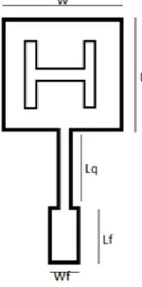
The H-shaped DGS [12] has been embedded in the ground plane of the proposed antenna which consists of the two rectangular slots and one rectangular connecting slot in the ground plane as shown in Figure 2. Figure 4 it shows the bottom view of proposed antenna with DGS.
Figure 2: Top view of conventional square MSA and the defect used
ISSN(Online): 2320-9801 ISSN (Print): 2320-9798
I
nternational
J
ournal of
I
nnovative
R
esearch in
C
omputer
and
C
ommunication
E
ngineering
(An ISO 3297: 2007 Certified Organization)
Vol. 3, Issue 2, February 2015
IV. SIMULATIONRESULTS
The S11 parameters for the proposed antennas are calculated and simulated reflection coefficients results are presented and compared with each other and are shown in Figure 5.From the above figure it is observed that antenna-1 is resonating at 1.61 GHz with impedance bandwidth of 500MHz when compared to conventional antenna, antenna-1 is showing improved impedance bandwidth of 200MHz. Further all compared results are tabulated in Table-1.
Figure 5: Reflection co-efficient verses frequency graph.
Since the proposed antenna with DGS are resonating below the designed frequency. The size reduction value when compared with conventional antenna in terms of percentage is also tabulated.
V. CONCLUSIONANDFUTUREWORK
From the detailed study it is observed that the conventional antenna is designed for 2.4GHz and further an H-shaped DGS is incorporated exactly below the patch and by doing this it is observed that antenna is resonating at the lower frequencies. By varying the dimensions of ‘a’ and ‘b’ of DGS it is further obtained that resonating frequency is shifting
ANTENNAS
Dimension DGS
FR R_Coeff BW
% BW
Size Reduc%
A B
S_con - - 2.36 -15.50dB 1.69 40 0
R_con - - 2.32 -12.62dB 1.72 40 0
R-1 0.2 1.4 1.70 -15.25dB 2.35 40 41.17
ISSN(Online): 2320-9801 ISSN (Print): 2320-9798
I
nternational
J
ournal of
I
nnovative
R
esearch in
C
omputer
and
C
ommunication
E
ngineering
(An ISO 3297: 2007 Certified Organization)
Vol. 3, Issue 2, February 2015
to lower frequency and from the comparative study the obtained maximum size reduction is 46.34%. By embedding DGS bandwidth, radiation pattern and gain are also improved.
REFERENCES
1. F. Yang, and Y. R. Samii, Electromagnetic band gap structures in antenna engineering, Cambridge University Press, 2008.
2. E Yablonovitch, “Inhabitted spontaneous emission in solid state-state physics and electronics,” Physics Review Letters, vol 58, no. 20, pp., 2059-2062, 1987.
3. E Ozbay, A. Abeyta, G Tuttle “Measurement of a three-dimensional photonic band in a crystal structure made of dielectric rods,” Phys. Rev B Condens matter, vol 50 no 3 pp. 1945-48 July 1994.
4. V R Adisic et al. “Novel 2-D Photonic band gap structure for microstrip line,” IEEE Microwave and Guided wave letter vole 8, no 2, pp. 69-71 Feb 1998.
5. Dalia M.N. Elsheakh, Hala A “Antenna design with electromagnetic band gap structure,” Electronic research institute. Giza.
6. D. Guha, M. Biswas, and Chandrakanta Kumar, “Printed antenna design using DGS: A review of fundamentals and state-of-the-art developments” Forum for Electromagnetic research methods and application technologies (FERMAT).
7. Sajjad Ur Rehman, Abdel Fattah,” Reconfigurable Band stop Filter Using Defected Ground Structures,” IEEE-2013.
8. S L Mallikarjun, P M hadalgi, P V Hunagund “Experimental study on development of microstrip array antenna loaded with DMS and DGS for Wide-band Operation” Bangalore ISM-10, pp- 67-71 2010
9. S L Mallikarjun, P M hadalgi, P V Hunagund “Developments of compact microstrip array antennas with DGS for broader bandwidth and beam.” IJEE, 3 (1), pp 25-27 2011.
10. S L Mallikarjun, P M hadalgi, P V Hunagund “Study on effects of rectangular DMS and DGS on 4 and 8 elements rectangular microstrip linear array antennas.” Vol 10, pp 13-16, 2011.
11. Shital S. Bramhe, Milind S. Narlawar, S. L. Badjate, Reconfigurable monopole Antenna with Defected Ground Structure for Cognitive Radio Application (IJAREEIE – ISSN: 2320-3765) Vol. 3, Issue 4, April 2014
12. Rammohan Mudgal, Laxmi Shrivastava International Journal of Technology Enhancements and Emerging Engineering Research, Vol 2, Issue 2, ISSN 2347-4289.
BIOGRAPHY