ABSTRACT
LIN, SHIYONG. Heterogeneous Deformable Object Modeling for Medical Surgical Simulation and Collaborative Product Development with Haptic Interfaces. (Under the direction of Dr. Yuan-Shin Lee and Dr. Roger Narayan.)
This research focuses on the investigation of heterogeneous deformable object modeling, physically based simulation, haptic force rendering and collaborative techniques for medical surgical simulation, virtual prototyping and collaborative product development.
Heterogeneous deformable models can be used to present internal geometric structures and different material properties of biological tissues and other soft-material objects for many Virtual Reality (VR) systems like surgical simulators. Cutting simulation is an important component of VR systems to modify the topology of deformable models. In this paper, a tri-ray node snapping algorithm is presented to generate volumetric heterogeneous mass spring models from a set of interface surfaces between different materials of deformable objects. A constrained local static integration method is proposed to quickly find the equilibrium solution of physically-based deformation behaviors. A 3D node snapping algorithm is developed to implement the topology modification on heterogeneous deformable models. Smooth cut is generated directly by duplicating and displacing mass points that are snapped along cutting planes. Sets of triangular surfaces representing different soft tissues are generated along the new cut to present internal geometric structures and corresponding material properties. A quasi-static algorithm is presented to refine the mesh in the vicinity of new cuts. A lab-built 6-DOF (degree of freedom) input and 5-DOF output haptic interface system is integrated with the developed system to provide force-torque feedback to users.
approaches by Verlet integration are used to synchronize graphic and haptic data transmitted over the network.
Heterogeneous Deformable Object Modeling for Medical Surgical
Simulation and Collaborative Product Development with Haptic Interfaces
By
Shiyong Lin
A dissertation submitted to the Graduate Faculty of North Carolina State University
In partial fulfillment of the Requirements for the Degree of
Doctor of Philosophy
Industrial and Systems Engineering
Raleigh December, 2007
Approved by:
__________________ __________________
Dr. Yuan-Shin Lee Dr. Roger J. Narayan
Chair of Advisory Committee Co-Chair of Advisory Committee
__________________ __________________
Dr. Ezat T. Sanii Dr. Christopher G. Healey
DEDICATION
BIOGRAPHY
ACKNOWLEDGEMENTS
I would like to express my sincere gratitude to my advisor, Dr. Yuan-Shin Lee, for his
continuous support, guidance and encouragement throughout my research work at North
Carolina State University. I would like to express my deep appreciation to my co-advisor, Dr.
Roger Narayan, for his help and suggestion in my research. I would like to thank Dr. Ezat T.
Sanii, and Dr. Christopher G. Healey for serving in my doctoral dissertation committee, and
for their time and suggestions. I would also like to thank Dr. Allen Chao and Dr. Eric Weibe
for their support and suggestions during my doctoral examination.
I sincerely thank my research group mates: Yongfu Ren, Weihang Zhu, Susana
Lai-Yuen, Abhinand Pamali, Ron Aman, Apichart Boonma, Deyao Ren, Yingjie Li, Plawut
Wongwiwat, Manida Swangnetr and Plamen Velinski for their valuable suggestions, advice,
and help during my years at NC State. I deeply enjoy every moment we spent together in the
old office in Park Shops and the new office in Daniels Hall.
I would like to thank our visiting professors to our research group, Dr. Ajay Joneja, Dr.
Jongyun Jung, Dr. Hayong Shin and Dr. Sungin Bae for their valuable suggestions and
discussions during our group meetings.
I also would like to thank my friends for their continuous support and encouragement. I
specially thank all members of our Volleyball Team and I will definitely miss the time we
played together.
Finally, I greatly thank my parents for their love, support and encouragement through
Table of Contents
List of Figures ... viii
List of Tables ... xi
Chapter 1 Introduction ...1
1.1 Motivation... 1
1.2 Research objectives... 2
1.3 Dissertation Organization ... 3
Chapter 2 Literature Review...5
2.1 Deformable object modeling and simulation... 5
2.1.1 Deformable object modeling methods ... 5
2.1.2 Generation of deformable object models ... 7
2.1.3 Solving the equilibrium of mass spring system ... 8
2.2 Topology modification and mesh relaxation for cutting simulation... 8
2.2.1 Topology modification approaches... 9
2.2.2 Mesh relaxation... 10
2.3 Haptic interfaces and force rendering ... 11
2.3.1 Haptic interfaces ... 11
2.3.2 Tool-object interaction force rendering ... 12
2.4 Network communication technology for collaborative VR systems ... 13
2.5 Summary ... 14
Chapter 3 Tri-ray Node Snapping Algorithm and Heterogeneous Soft Tissue Modeling for Medical Surgical Simulation...15
3.1 Introduction... 15
3.2 Modeling of Deformable Biological Soft Tissues ... 17
3.3 Tri-ray Node Snapping Algorithm for Constructing Heterogeneous Models ... 19
3.5 Summary ... 32
Chapter 4 5-DOF Haptic Force Feedback Analysis for Heterogeneous Material Modeling and Virtual Prototyping...33
4.1 Introduction... 33
4.2 Haptic force feedback interface and control system ... 34
4.2.1 Mechanism and control system of the haptic device ... 35
4.2.2 Kinematics analysis of the haptic force feedback device ... 38
4.3 Haptic force rendering for deforming soft models ... 42
4.3.1 Modeling interaction forces on deformable objects... 43
4.3.2 Static and dynamic friction force modeling... 46
4.3.3 Total spring force and torque calculation ... 50
4.3.4 Force model with multiple contact points... 52
4.4 Summary ... 54
Chapter 5 Three-dimensional Medical Cutting Simulation Techniques on Heterogeneous Deformable Models ...55
5.1 Introduction... 55
5.2 Cutting algorithm on heterogeneous models ... 57
5.2.1 Surface cut snapping ... 59
5.2.2 Inside cut snapping ... 62
5.2.3 Opening the cut ... 64
5.2.4 Internal triangle generation at the cutting site... 68
5.3 Quasi-Static Algorithm for Mesh refinement ... 71
5.4 Summary ... 75
Chapter 6 Hybrid Network Architecture and Control Techniques for Collaborative Haptic Applications ...76
6.1 Introduction... 76
6.2 Challenges of heterogeneous deformable object simulation ... 78
6.3 Architecture and control of the collaborative haptic VR system ... 81
6.3.2 Data transmission and protocols ... 84
6.3.3 Data synchronization for accurate collaboration ... 86
6.3.4 Data interpolation and extrapolation by Verlet integration ... 89
6.4 Summery ... 93
Chapter 7 Implementations and Results ...94
7.1 System implementations ... 94
7.2 Examples of deformable object modeling and virtual prototyping ... 95
7.3 Examples of bio-tissue modeling and surgical simulation ... 100
7.4 Examples of collaborative haptic VR system ... 115
7.5 Summary ... 124
Chapter 8 Conclusions and Future Research ...125
8.1 Conclusions... 125
8.2 Future Research ... 126
List of Figures
Figure 2.1 Example of Finite Element Model...6
Figure 2.2 Example of Mass Spring Model ...7
Figure 2.3 Different topological modification approaches ...9
Figure 2.4 Lab-built haptic force feedback device...12
Figure 2.5 Haptic rendering of a sphere in a virtual environment ...13
Figure 3.1 Bio-tissue example and boundary surfaces of anterior abdominal wall ...16
Figure 3.2 Hexahedral element of volumetric Mass Spring Model ...17
Figure 3.3 Heterogeneous deformable models with interface surface between tissues ...18
Figure 3.4 Procedure of constructing heterogeneous volumetric models ...20
Figure 3.5 Mass points snapped to intersection surface points ...21
Figure 3.6 Flowchart of generating the volumetric heterogeneous models ...22
Figure 3.7 Mass point generation with different bio-tissue materials ...23
Figure 3.8 Mass point generation of human thigh example ...24
Figure 3.9 Technique for interface surface marching ...25
Figure 3.10 Flowchart of interface marching algorithm...27
Figure 3.11 Rigid (incompressible) spring at its extreme length...28
Figure 3.12 Neighboring bounding box (NBB) of a mass point...30
Figure 4.1 Mechanism structure of the 5-DOF haptic force feedback device ...35
Figure 4.2 The controller hardware of the 5-DOF haptic device ...36
Figure 4.3 The controller elements and layout of the 5-DOF haptic device [Zhu 2003] ...37
Figure 4.4 The haptic device hardware working flow...38
Figure 4.5 Haptic device coordinate systems and rotation angle definition ...38
Figure 4.6 Force and torque model of the haptic device ...40
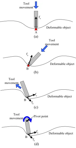
Figure 4.7 Different cases of interaction between a tool and a deformable object ...44
Figure 4.8 Deforming an object with soft and hard materials...45
Figure 4.11 Tool-object interaction examples caused by friction...48
Figure 4.12 Static friction modeling ...49
Figure 4.13 Torque calculation around the pivot point of the haptic probe ...50
Figure 4.14 Contact forces between a haptic probe and internal heterogeneous structure...51
Figure 4.15 Line contact between a haptic probe and a deformable object...52
Figure 4.16 Surface contact between a haptic probe and a deformable object...53
Figure 5.1 Flow chart of 3D node snapping cutting algorithm ...57
Figure 5.2 Definitions for volumetric deformable object cutting ...58
Figure 5.3 Surface cut points sampling and mass points snapping examples ...59
Figure 5.4 Triangle tracking along the tool path and special surface snapping cases...61
Figure 5.5 Surface cut snapping examples ...62
Figure 5.6 Inside cut snapping example...63
Figure 5.7 Cut opening generation process ...65
Figure 5.8 Cutting into a heterogeneous model ...68
Figure 5.9 Different cutting cases on a heterogeneous model ...70
Figure 5.10Flow chart of quasi-static mesh relaxation algorithm ...73
Figure 6.1 Comparison between rigid and deformable object manipulation ...79
Figure 6.2 Bounding volume hierarchy update of deformable objects ...80
Figure 6.3 Architecture of the proposed collaborative haptic virtual prototyping system...82
Figure 6.4 Network traffic problems during data transmission...84
Figure 6.5 Data flow between clients and server ...85
Figure 6.6 Minimizing network delay by artificial time compensation ...87
Figure 6.7 Data synchronization problems in network data transmission ...88
Figure 6.8 Data interpolation and extrapolation...89
Figure 6.9 Flow chart of missing data estimation ...92
Figure 7.1 Setup of a virtual prototyping system with a lab-built 5-DOF haptic interface...95
Figure 7.2 A heterogeneous handle model with soft materials ...96
Figure 7.4 Comparison of haptic response forces at different deformation levels on soft
materials ...97
Figure 7.5 Example of using the developed haptic rendering system to test and evaluate product design with heterogeneous deformable materials...99
Figure 7.6 Comparison of deformation testing results ...100
Figure 7.7 Lab-setup of heterogeneous deformable object modeling and surgical simulation system with a haptic force-feedback device ...101
Figure 7.8 Construction of a heterogeneous volumetric model from medical images...102
Figure 7.9 A heterogeneous human leg model with detailed mass points and springs ...103
Figure 7.10Response forces when pushing model along different tool paths ...104
Figure 7.11Deformation on an example of human leg model with rigid bones ...105
Figure 7.12Surgical cutting simulation system using a Phantom haptic device...106
Figure 7.13Cutting calculation time at an approximately constant cutting speed ...107
Figure 7.14Intersection and snapping examples of cutting on a model surface ...108
Figure 7.15Arbitrary cutting result and new generated springs at the cutting site ...109
Figure 7.16Cutting results before and after mesh relaxation...110
Figure 7.17Cut width variation due to the cutting depth change ...111
Figure 7.18Multiple layers at different cutting sites ...112
Figure 7.19Cutting results on different cutting depths ...113
Figure 7.20Results of continuous cuts on a leg model ...114
Figure 7.21Lab setup of the collaborative haptic system ...115
Figure 7.22An example of testing soft material properties of a product design model...116
Figure 7.23Collaborative assembly and manipulation of an example handler model ...117
Figure 7.24Data transmission time with and without network time delay ...118
Figure 7.25Haptic tool motion jittering problems ...119
Figure 7.26Parts alignment process without artificial time compensation ...120
Figure 7.27Parts alignment process with artificial time compensation ...121
Figure 7.28Comparison between fixed and adaptive artificial time compensation...122
List of Tables
Table 7.1 Error analysis of the results by interpolation and extrapolation ...124
Chapter 1
Introduction
1.1
Motivation
Deformable objects have received increasing attention due to their importance in a variety of Virtual Reality (VR) applications. Most existing deformable objects like biological soft tissues consist of heterogeneous materials with complex internal geometric structures. Modeling and simulation of heterogeneous deformable objects can greatly enhance the realism and fidelity of VR systems such as surgical simulation and computer games [Sarni
2004, Georgii 2005]. However, most researches on deformable object modeling assume
homogeneous material property and ignore the variance of the internal geometric structures [Basdogan 2004]. Homogeneous deformable models are acceptable for some simple applications where accurate simulation results are not required. However, in the applications demanding high realism and fidelity, deformable object models should contain accurate internal geometric structures and proper material properties. Surgical simulation is such a case that heterogeneous soft tissue models are of great importance to differentiate healthy soft tissues such as skin, fat tissues, muscles, vessels or nerves, from unhealthy ones.
In many VR systems, new deformable models often need to be generated efficiently for different objects. For example in surgical simulation, patient-specific models of soft tissues are usually required for the presurgical rehearsal and the postsurgical analysis. Current virtual simulation systems lack the flexibility of creating new deformable models. To generate heterogeneous deformable models, internal geometric structures and material properties need to be incorporated. This makes it a more challenging task than generating homogeneous deformable models.
approaches to generate realistic cuts that can show internal geometric structures and material properties of heterogeneous models. 3D cutting techniques on the heterogeneous deformable models is required to generate realistic cuts and simulate realistic cutting operations.
With the rapid progress of haptics technology, traditional visual-only VR systems have been gradually shifted to haptic based VR systems, e.g. haptic virtual sculpting systems and surgical simulators. Users can interact with virtual objects in virtual environments via haptic interfaces. Haptic interfaces facilitate the implementation of high-fidelity VR environments for users, by providing them with tactile senses. The main issue of integrating haptic interfaces into virtual environments is to generate realistic force/torque feedback. Material properties such as stiffness and roughness play a critical role in generating proper force/torque feedback during tool-object interaction. Heterogeneous deformable models that incorporate appropriate material properties proposed can be utilized to calculate accurate force/torque feedback.
The advent of network communication technology has brought VR applications to a new horizon. Collaborative VR systems has been used in computer games, design and manufacturing. Haptic-based collaborative VR systems with deformable models have great potential in remote surgery training/operation, tele-robotics and other tele-applications. Research on integration and control of haptic interfaces and deformable models in collaborative virtual environments is still in its infancy. Network synchronization and intensive computation caused by haptic rendering and deformable object simulation are the main challenges to be addressed.
1.2
Research objectives
The objective of this research is to investigate and develop modeling, simulation and communication techniques for soft material (especially biological soft tissues) modeling, medical simulation, product design and virtual prototyping, and collaborative VR systems via haptic interfaces. Several research issues are addressed in this paper:
1. Heterogeneous deformable object modeling and physically based simulation: A
deformable object models from a set of interface surfaces between different materials. Interface surfaces are explicitly preserved in the deformable models. These interface surfaces can be used to differentiate different materials. A constrained local static integration method is presented for physically based deformation simulation. This static method is efficient and stable for real-time VR applications.
2. Haptic force analysis for heterogeneous deformable modeling:A lab-built haptic
interface is studied and its controller system is developed. This haptic interface is utilized to provide force feedback to users. A comprehensive force model is introduced to analyze response forces during the tool-object interaction.
3. Topology modification and mesh relaxation for cutting simulation on heterogeneous deformable objects: A 3D cutting algorithm is proposed to
generate realistic cuts on heterogeneous deformable objects. Internal geometric structures and material properties are presented at the cut site. After the cutting operation, mesh relaxation is needed to refine the modified mesh. A quasi-static
algorithm is presented to achieve quick and accurate results of mesh refinement.
4. Network architecture and data synchronization for collaborative haptic VR systems: A hybrid client/server architecture is proposed to balance the
computational burden brought by haptic rendering and deformable object simulation. Data synchronization problems during network communication are identified and addressed.
The marriage of heterogeneous deformable objects, haptic interfaces and collaborative technique has brought opportunities as well as challenges into the arena of VR. We hope our research can contribute to the VR research area and trigger more interesting and significant research and applications in the future.
1.3
Dissertation Organization
Chapter 2 discusses the literature review on current work of heterogeneous deformable object modeling, physically based simulation, haptic force rendering and medical cutting techniques.
Chapter 3 presents techniques of generating volumetric heterogeneous mass spring models. Real-time physical simulation of heterogeneous deformable objects is solved by a proposed constrained local static integration method.
Chapter 4 introduces a lab-built haptic interface and its controller development. Response forces and haptic rendering between the haptic tool and deformable objects are analyzed using the proposed force model.
Chapter 5 describes the medical cutting techniques on volumetric heterogeneous deformable models. Realistic cuts are generated to display internal structures and material properties.
Chapter 6 describes the challenges of integrating deformable modeling and haptic interfaces into collaborative VR applications. A system architecture and data synchronization techniques are presented to address the problems.
Chapter 7 presents system implementations and results by using the proposed techniques.
Chapter 2
Literature Review
In this chapter, we review the issues and previous work related to deformable object modeling, physically based simulation, haptic force analysis, cutting techniques and network collaborative techniques on deformable models. These research issues will be further explored and referred frequently in the following chapters.
2.1 Deformable object modeling and simulation
With the rapid progress made in modeling and simulation area, increasingly high levels of realism are demanded by Virtual Reality (VR) applications. More complex virtual object models with complicated geometry and physical properties are required in the virtual environments. Physically-based deformable modeling and simulation are of growing interest in the fields such as medical training, entertainment industry, design and manufacturing industry [Al-khalifah 2004, Akagi 2006, Dewaele 2004, Lin 2007b]. Well-developed deformable object modeling and simulation techniques can enhance the realism and fidelity of virtual environments and open up more applications. This section is a brief review of deformable object modeling and simulation techniques.
2.1.1 Deformable object modeling methods
constraints are applied together for physically based modeling. Physically-based modeling methods are preferred to simulate realistic deformable objects in virtual environments.
P1
P4
P3 P2
Figure 2.1 Example of a Finite Element Model and its elements
Figure 2.2 Example of a Mass Spring Model [Gibson 1997]
Recently, realistic material properties including nonlinear elasticity, anisotropy and heterogeneity have been used to model some complicated deformable objects such as biological soft tissues. Nonlinear elasticity of soft tissue was modeled by nonlinear strain tensor formulation in FEM [Mendoza 2003] or nonlinear spring coefficients in Mass Spring Model [Mohr 2003]. Some innovative research on anisotropic modeling was reported in [Bourguignon 2000, Picinbono 2003]. But heterogeneous deformable object modeling is seldom explored. This is the main issue that will be addressed in this paper.
2.1.2 Generation of deformable object models
2.1.3 Solving the equilibrium of mass spring system
Deformable objects are usually modeled as dynamic systems, which are governed by a set of second-order Ordinary Differential Equations (ODE). A variety of numerical integration schemes are available to solve these Ordinary Differential Equations, such as explicit Euler method, 4th-order Runge-Kutta method and Verlet method [Gibson 1997, Bielser 1999, Sørensen 2006]. Explicit Euler method can achieve fastest computation with the error of O(h2), where h is the numerical integration time step. A small h is required by
explicit Euler method to maintain the numerical stability of the system. Runge-Kutta method has good stability and accuracy with the error of O(h5), but it is computationally expensive.
All these numerical integration schemes suffer the same problem of slow convergence to system equilibrium, since each mass point may oscillate around its equilibrium position for a
few times. A large h can speed up the convergence but may bring the system instability.
2.2 Topology modification and mesh relaxation for cutting simulation
2.2.1 Topology modification approaches
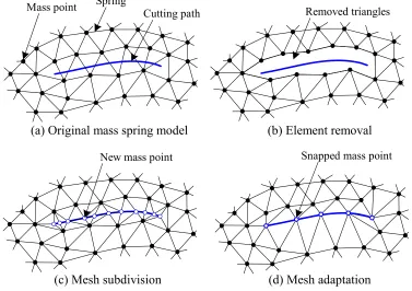
During the cutting operation, the cut is generated along the cutting path and model topology is modified accordingly in the vicinity of the cut site. Four types of topological modification approaches have been often used, e.g. element removal, mesh subdivision, mesh adaptation and hybrid methods. Figure 2.3 gives the illustrative diagram of these methods on triangular surface meshes.
Cutting path
Mass point Spring Removed triangles
New mass point Snapped mass point
(a) Original mass spring model
(d) Mesh adaptation (c) Mesh subdivision
(b) Element removal
Figure 2.3 Different topological modification approaches
Element removal (Figure 2.3(b)) is to directly remove an element that the cutting tool intersects [Delingette 1999]. Despite of its simplicity and computational efficiency, this method cannot present smooth cut due to visual artifacts resulted from element removal. In addition, total mass and volume cannot be preserved after removing intersected elements.
planes. However, the method is computationally expensive since there are many subdivision cases and the number of elements is increased. Another drawback is that small or degenerated elements may be generated near the cut site, which can cause instability of the simulation.
Mesh adaptation (or node snapping) shown in Figure 2.3(d) can generate good cutting path without creating new elements. Vertices of elements or mass points near cutting path are snapped to the closest points on the cutting path. And associated edges or springs are aligned along the cutting path. Mesh adaptation has been applied in cutting triangular mesh and tetrahedral mesh [Nienhuys 2001]. The quality of resulting incision is limited by initial mesh resolution. The smaller the elements, the smoother the cut can be achieved. Degenerated elements of improper shape may also occur as the mesh subdivision approach.
Mesh subdivision and adaptation methods can be combined to take advantages of both approaches, i.e. smooth cut without introducing too many new elements. Gasson et al. (2004) presented a repositioning and re-triangulation method of cutting on the surface Mass Spring model. Harders et al. (2005) proposed a similar hybrid approach for tetrahedral mesh cutting.
2.2.2 Mesh relaxation
Degeneracy such as small-size elements or badly-shaped elements may be generated after most topology modification approaches are applied. Degenerated elements can make the system unstable for afterward physical simulation. Such elements should be normalized, which is often called mesh relaxation.
ignores dynamic inertial and damping forces in order to speed up the numerical integration of deformable object simulation. We apply this algorithm to mesh relaxation to take advantage of its merit of efficient computation and fast convergence. The goal of mesh relaxation is to quickly obtain relaxation result rather than dynamic relaxation process.
2.3 Haptic interfaces and force rendering
In current VR systems, haptic interfaces are often used as virtual tools to control or manipulate virtual models. One focus of this paper is on the utilization of haptic interfaces in virtual environments for accurate force rendering of heterogeneous deformable objects. For this reason, haptic interfaces are introduced in this section. Techniques for haptic force feedback calculation and analysis are also discussed.
2.3.1 Haptic interfaces
The recent development of haptic interfaces has promoted the haptic applications in various fields including medicine, education, industry and so forth. There are many kinds of different haptic devices that have been developed. According to [Srinivasan 1997], haptic devices can be classified as ground-based or body-based devices. Ground-based haptic devices are usually grounded somewhere like a desktop. This kind of devices includes
Joysticks, Pen-based Masters, Robot arms, Floor-Grounded Exoskeletons etc. Body-based
haptic devices are usually portable and smaller than ground-based devices, including Arm
Exoskeletons, Hand Master, CyberForce Glove etc.
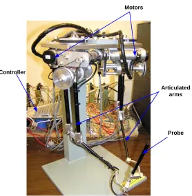
In our earlier work, a lab-built 5-DOF haptic force-torque feedback interface has been developed [Zhu 2004a, 2004b]. A SensAble Phantom Desktop will also be utilized in this paper. Both the lab-built haptic interface and the Phantom Desktop are pen-based desktop haptic devices. Figure 2.4 shows the lab-built haptic device, which was designed and
manufactured by Suzuki Inc. Japan. Its controller system and software driver program are
Probe Articulated
arms Motors
Controller
Figure 2.4 Lab-built haptic force feedback device
2.3.2 Tool-object interaction force rendering
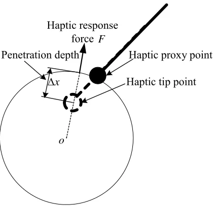
x Δ
F
o
Haptic tip point Haptic proxy point Penetration depth
Haptic response force
Figure 2.5 Haptic rendering of a sphere in a virtual environment
Haptic force feedback can be easily calculated and rendered by most 3-DOF haptic interfaces. However, torque calculation and rendering are different. Torque feedback is critical in many applications that demand accurate force-torque feedback like surgical simulation and virtual sculpting [Lin 2007a, Zhu 2004]. In this paper, response forces and torques are calculated and rendered via our 5-DOF haptic interface device.
2.4 Network communication technology for collaborative VR systems
The most critical part of a collaborative VR system is its network architecture. Based on the functional relationship existing between the elements of the network, the network can be classified into active networking architecture, client-server architecture and peer-to-peer architecture. Client-server and peer-to-peer architectures are most commonly used in collaborative systems [Memon 1997]. In client-server architecture, most computation and simulation tasks are usually performed at the server. The main advantage is that only one data copy of the virtual environment is maintained so that data consistency is automatically
guaranteed. However, computational burden at the server might be too heavy.In peer-to-peer
than client-server architecture. However, the data consistency is very hard to maintain because each client has its own data of the same virtual environment.
Practically, neither client-server nor peer-to-peer architecture can be directly used for collaborative applications, especially when haptic interfaces and deformable models are integrated. Marsh et al [2006] presented a roaming-server hybrid architecture based on the two basic network architectures for a distributed virtual prototyping application. Iglesias et al. [2006] compared different architectures and suggested that computation was distributed at both client and server sides for their virtual assembly simulation system. However, both researches didn’t take into account the complexity of deformable object modeling and simulation in their collaborative systems, which is one of the research objectives in this paper.
2.5 Summary
Chapter 3
Tri-ray Node Snapping Algorithm and Heterogeneous Soft Tissue
Modeling for Medical Surgical Simulation
This chapter presents the modeling techniques of deformable bio-objects for medical
applications. A tri-ray node snapping algorithm is proposed to generate volumetric
heterogeneous deformable models from a set of object interface surfaces between different materials. Heterogeneous models can represent real internal geometric structures of soft
tissues and different material properties. A constrained local static integration method is
presented for the physical simulation of deformable objects. By integrating heterogeneous deformable models into VR systems, users can feel different materials by touching a deformable object via a haptic device.
3.1 Introduction
For medical applications, the techniques of modeling of bio-tissues and deformable objects are important and they are not easy tasks. Figure 3.1 shows the boundary surfaces and interface surfaces of human anterior abdominal wall. As shown in Figure 3.1, bio-tissue consists of different material properties and complex geometric information that are difficult in modeling. Heterogeneous deformable model representation is critical in modeling real
internal structures of deformable bio-objects with different material properties [Sarni 2004,
existing deformable objects consist of heterogeneous materials with complex internal structures and various material properties.
skin
facial
peritoneum rectus
muscles fat
Figure 3.1 Bio-tissue example and boundary surfaces of anterior abdominal wall
Heterogeneous deformable object models, combined with accurate haptic rendering techniques based on these models, provides great potential to enhance VR or MR. Especially in some virtual environments requiring high fidelity, deformable models should incorporate proper internal structures and material properties [Lin 2007a]. For example, in surgical simulation it is often necessary to differentiate healthy soft tissues such as skin, fat tissues, muscles, or vessels and nerves, from unhealthy ones. However, most current practices assume homogeneous material properties and ignore internal structure variance, which greatly limit the application [Basdogan 2004]. In VR environments new deformable models often need to be generated efficiently. For example in surgical simulation, patient-specific models of new deformable objects are usually required for the presurgical rehearsal and postsurgical analysis. Current simulation systems lack the flexibility of creating new deformable models, especially heterogeneous deformable models.
Parts of human body such as anterior abdominal wall, leg and thigh are modeled using the proposed techniques for demonstration. Other heterogeneous deformable objects can be modeled by the same techniques.
The remainder of this chapter is organized as follows. Section 3.2 provides a review of the heterogeneous modeling of deformable objects. Section 3.3 presents the detailed node snapping algorithm for modeling the deformable heterogeneous objects. Section 3.4 discusses the system modeling of spring force rendering and the detailed techniques of solving the deformation equilibrium. Section 3.5 presents the summary.
3.2 Modeling of Deformable Biological Soft Tissues
Biological soft tissues, as shown in Figure 3.1, are viscoelastic, anisotropic and
heterogeneous deformable objects [Fung 1993]. Deformable model generation is a process of
discretizing volumetric objects into mass points and springs in Mass Spring Model or small elements in Finite Element Model. Most simulation systems used mesh generation approaches of Finite Element Analysis (FEA) to generate small elements such as tetrahedra or hexahedra for Finite Element Model [Meier 2005]. Many Mass Spring models can also be generated from these tetrahedra or hexahedra by taking their vertices as mass points and edges as springs [Mollemans 2003]. However, deformable models generated by these approaches are mostly homogeneous.
mass point layer spring shear spring structural spring
Figure 3.2 shows the hexahedral elements used for the Mass Spring modelling of the heterogeneous materials. The hexahedral elements are more stable and controllable than the tetrahedral elements (Lin 2007a). Mass points on the same layer are connected by structural springs and diagonal shear springs. Structural springs stand for tensile and compressive stress, while shear springs are mainly used to represent the shear stress. Layer springs are added to connect neighbouring tissue layers. This regular structure can keep the system stable and prevent self-intersection during simulation.
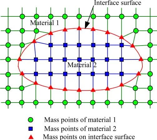
A heterogeneous deformable object may include several materials, as shown in Figure 3.3. For example, a human leg consists of skin, fat tissue, various muscles, bone and so on. To generate such a heterogeneous model, geometry of each material inside the object is required, such as its interface surfaces. Most interface surfaces between materials can be acquired from medical images such as CT and MRI images, although it remains as a challenge to differentiate some very close materials.
Material 1
Interface surface
Material 2
Mass points of material 1 Mass points of material 2 Mass points on interface surface
In some applications like Computer Aided Design (CAD), smooth variation between different materials is traditionally applied by interpolation [Samanta 2005]. For heterogeneous deformable modeling of biological soft tissues, a meaningful interface layer usually exists between two different materials, as shown in Figure 3.3. For instance, muscles are often enclosed by the muscle sheath and bones are enclosed by the periosteum. These interface surfaces provide appropriate visual clue to differentiate soft tissues. They can also be used for specifying different material properties such as mass, texture and stiffness.
Heterogeneous modeling and simulation require more computational power than homogeneous modeling since more topological constraints and material properties are involved. For interactive VR applications like surgical simulation and computer games, real-time computation has the highest priority. Algorithms used in heterogeneous modeling have to be efficient. In addition, the balance between the level of details in heterogeneous modeling and the computational efficiency needs to be taken into account carefully.
3.3 Tri-ray Node Snapping Algorithm for Constructing Heterogeneous
Models
In this chapter, we present a technique of constructing heterogeneous deformable models. The key point of heterogeneous model generation is to retain a single mass spring layer for the outmost surface of a whole object and also individual mass spring layer respectively for each internal interface surface. For rest part of the deformable model except these interface surfaces, uniform mass spring network is created to connect these interface mass spring layers. For better illustration of the idea of heterogeneous deformable model generation, we give two definitions:
Definition 1: mass points of the same material are defined as homogeneous mass
points; otherwise they are heterogeneous mass points.
Definition 2: springs connecting homogeneous mass points are defined as
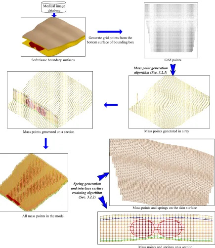
Medical image database
Soft tissue boundary surfaces
Generate grid points from the bottom surface of bounding box
Grid points
Mass points generated in a ray Mass points generated on a section
All mass points in the model
Mass points and springs on a section Mass point generation
algorithm (Sec. 3.2.1)
Spring generation and interface surface
retaining algorithm (Sec. 3.2.2)
Mass points and springs on the skin surface
Figure 3.4 Procedure of constructing heterogeneous volumetric models
algorithm, (ii) springs connection and interface marching technique, and (iii) physical parameter specification.
From the boundary and interface surfaces, mass points are generated by a tri-ray node snapping algorithm similar to the Ray Casting algorithm in Computer Graphics. Based on the idea of the tri-dexel volumetric model developed in our earlier work presented in [Ren 2006], parallel rays are cast respectively three orthogonal directions to intersect the boundary surface and interface surfaces, in order to preserve the shape of these surfaces accurately. Figure 3.4 shows the procedure of using tri-ray tracing technique to construct volumetric heterogeneous models. First, rays in one direction are used to generate all mass points. Then rays in the other two directions are used to adjust the positions of mass points around interface surfaces, without generating new mass points.
P[i,j,0] P[i,j,1] P[i,j,k] P[i,j,k+1] Y Z X P[i,j,0] P[i,j,1] P[i,j,k] P[i,j,k+1] Intersection point j k i Interface surface Snapping Grid points d Δ intersect P (a) (b)
(a) Mass points before snapping. (b) Mass points after snapping onto surface Figure 3.5 Mass points snapped to intersection surface points
As shown in Figure 3.5, uniform rays are cast from grid points P[i, j, 0] on the 2D
X-Y plane to intersect with all the accessible boundary surfaces. Mass points are evenly generated at the interval Δd along the ray shown as follows:
r d k j i P k j i
P[, , +1]= [, , ]+Δ * (3.1)
where r is a unit vector in the ray direction; Δd is the grid distance between adjacent mass
points. Δd is defined by the minimum of dmin and dthrehold as follows: }
{d , dmin Max
d = threshold
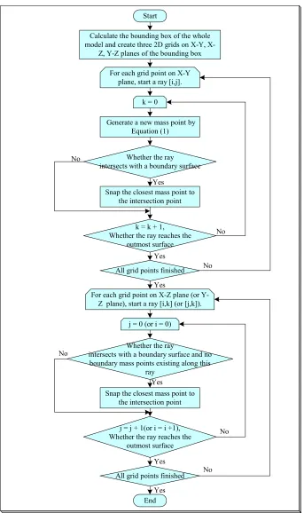
Calculate the bounding box of the whole model and create three 2D grids on Y,
X-Z, Y-Z planes of the bounding box
For each grid point on X-Y plane, start a ray [i,j].
Whether the ray intersects with a boundary surface
All grid points finished No
Snap the closest mass point to the intersection point
Yes
No
Yes
Generate a new mass point by Equation (1)
k = 0
k = k + 1, Whether the ray reaches the
outmost surface
No Yes
End Start
For each grid point on X-Z plane (or Y-Z plane), start a ray [i,k] (or [j,k]).
j = 0 (or i = 0)
Whether the ray
intersects with a boundary surface and no boundary mass points existing along this
ray No
Snap the closest mass point to the intersection point
Yes
All grid points finished
Yes j = j + 1(or i = i +1), Whether the ray reaches the
outmost surface
Yes
No
In Equation (3.2), dminis the minimal distance between two intersection points of different
interface surfaces in the model, and dthrehold is a preset value to control the mass point density
in case dminis too small. As shown in Figure 3.5(a), when a ray intersects an interface surface
at the point Pintersect, the closest mass point to Pintersect along the ray is P[i,j,k] if the following
condition is true:
2 ] , ,
[i j k d P
Pintersect− ≤Δ (3.3)
Using Equation (3.3), a mass point can be snapped into its closest intersection point
on an interface surface. As shown in Figure 3.7(b), P[i, j, k] is the closest mass point to
intersect
P and it is snapped to Pintersect as a result. Figure 3.6 shows the flowchart of the detailed
procedures of generating mass points of heterogeneous volumetric models.
Material 1
Original interface surface
(a) (b)
Material 2
Mass points generation direction
[i,k] [i,k]
[i-1,k+1]
(c)
Z
X
Mass points of Material 1 Mass points of Material 2 Mass points on interface surface
[i,k]
[i+3,k+1] [i-1,k+1]
M N
New interface surface
[i+3,k+1]
[i+2,k] [i+2,k]
(a) Generate mass points in Z direction; (b) Adjust mass points in X direction; (c) Final mass points
Figure 3.7 Mass point generation with different bio-tissue materials
gradually generated along the ray until the ray reaches the outmost boundary surface. Above process is repeated until all rays in Z direction are processed. After this step, newly generated mass points are shown in X-Z plane of Figure 3.7(a). However, mass points on the interface surface cannot separate Material 1 and Material 2. Neither can they preserve the shape of original interface surfaces, as shown in Figure 3.7(a).
Above problem is solved by adjusting some mass points around the interface surfaces, using rays in X and Y directions respectively. For example, rays along X are cast to intersect the interface surfaces. Existing mass points closest to the intersection points are snapped to these intersection points, without generating new mass points. Figure 3.7(b) shows an
example of adjusting mass points along X direction. Ray k+1 intersects the interface surface
at point M and point N. Mass point P[i-1,k+1] that is closest to point M and mass point
P[i+3, k+1] that is closest to point N are snapped to points M and N respectively. After the
mass point adjustment step, a smooth boundary interface is formed to separate the two materials as shown in Figure 3.7(c).
(a) Mass points generated along Z direction (b) Mass points adjusted along X direction X
Z Mass points on interface surfaces
Mass points inside materials
Mass point adjustment in
X direction
Figure 3.8 Mass point generation of a human thigh example
interface surfaces. The example shows that the node snapping algorithm can preserve boundary and interface shape of deformable objects during the construction of the heterogeneous deformable models.
Most mass points by the tri-ray node snapping algorithm are uniformly distributed inside the deformable model if they are not snapped onto any interface surface. These mass points maintain a regular neighboring topology so that they can be directly connected to their neighboring mass points by springs. On the other hand, mass points snapped onto interface surfaces are irregularly distributed due to snapping. Mass points snapped on an interface surface are supposed to form a single mass spring layer to represent this interface surface. However, direct neighboring mass point connection method is not able to achieve this.
[i,k]
[i-1,k-1]
[i,k]
[i-1,k-1]
Original interface surface
(b) (c)
k i
Material 1
[i,k]
Material 2
[i-1,k-1]
(a)
New generated interface surface Disconnected
interface surface Connected
interface surface
(a) Mass points generated by the tri-ray snapping algorithm. (b) Spring connected by
direct neighboring connection method. (c) Spring generation on the interface surface by homogeneous mass point search algorithm
Figure 3.9 Technique for interface surface marching
marching cube algorithm developed in our earlier work presented in [Zhu 2005], the interface surface is connected through marching along the 3D surface contour, as shown in Figure 3.9(b). In Figure 3.9(b), the original grid nodes generated by the tri-ray method are snapped onto the interface surface. When the marching along the interface contours stops, the interface contours need to be connected and merged. As shown in Figure 3.9(c), a continuous interface surface has been successfully constructed. Details of the Interface Marching Algorithm are shown in Figure 3.10.
The last step of heterogeneous deformable model generation is to assign material properties to mass points and springs. In our heterogeneous deformable models, different materials are separated by the interface surfaces. By selecting any mass point, all its homogeneous mass points can be chosen simultaneously and material properties like mass can be specified efficiently, which is an advantage of our heterogeneous model.
Check whether the two mass points are
homoogeneous
No
Whether the queue is empty
No
Yes
For each direct neighbor (right, left, top, bottom, front, back)
No Whether N = , or all direct
neighbors have been checked Yes
Yes Start
Creat a search queue and initialize the queue by putting a mass point on the interface surface
Generate the spring, N = N + 1
N =
Yes
Pop a mass point P[i,j,k] from the queue, neighboring homogeneous mass point
number N=0
No
End max N
max
N
For each diagonal neighbor
Check whether the two mass points are
homogeneous
Whether N = , or all diagonal neighbors have been checkedmax
N
No
No Yes
Yes
3.4 System Modeling of Spring Force Rendering and Solving Deformation
Equilibrium
Local deformation of soft tissues is often assumed in surgical simulators to reduce the computational burden of deformable object simulation [Nakao 2006]. In this chapter, local deformation is controlled by a preset small force value. Mass points are considered to be active only if their total spring forces are larger than the threshold force. Only active mass points are used in simulation.
In conventional Mass Spring Model, the spring force of a mass point i is often
calculated by total spring forces from its neighboring springs as following,
∑
=Δ = n
t it it it it i
d d l k f
0 r r
(3.4)
where kitis the spring coefficient between mass points i and t; Δlit is the spring length
deviation from its original length; drit is the direction vector pointing from mass point i to its
neighboring mass point t.
i
i
ig
j
j
ig
k
k
Spring extreme lengh Spring is
compressible Spring becomesincompressible
During the simulation, it is possible that a spring is over compressed or stretched to its extreme length as spring ij in Figure 3.11. In this case, Equation (3.4) becomes inaccurate
because the spring force will not change even if mass point i (Figure 3.11) is further pushed
down. In the extreme compression or stretching case, we assume a spring become a rigid object without break or fracture. A force accumulation method is presented to accumulate the
spring force acting on the rigid object. For example, spring ij in Figure 3.11 is extremely
compressed and considered as a rigid object. The spring force on one end mass point (e.g. mass point j) is accumulated to the other end mass point (e.g. mass point i) so that the total
spring force at mass point i is calculated as follows:
f d d l k f f d d l k f k k t i t n t jt jt jt jt j j j t n t it it it it i j i ⎪ ⎪ ⎩ ⎪ ⎪ ⎨ ⎧ + Δ = + Δ =
∑
∑
≠ ≠ ∈ ≠ ∈ } , , { } , { r r r rifΔlij≥αmaxlijorΔlij≤αminlij,Δljk≥αmaxljkorΔljk≤αminljk (3.5)
where niand njare the neighboring mass points of mass point i and j. fk can be calculated recursively by the second formula in Equation (3.5), if there are more extreme springs connecting to mass point k.
A mass point touching by the haptic tool is defined as contact mass point. Haptic feedback forces are calculated by interpolating spring forces of contact mass points. The force accumulation method and proper material properties from heterogeneous deformable models can guarantee realistic haptic force rendering for VR applications like surgical simulation.
To find the equilibrium state of a deformable object under deformation forces, the governing force system of the deformable object is formulated first. The mass spring system of a deformable object is a dynamic system, which is governed by following second order differential equations: i i i i i
ix dx g f
where mi,diare mass and damping coefficient of mass point i; x&&iandx&iare its acceleration
and velocity respectively;giis total external force andfiis total internal spring force of mass
point i. Several numerical integration schemes have been used to solve these Ordinary
Differential Equations, such as explicit Euler method, 4th-order Runge-Kutta method and Verlet method [Bielser 1999, Sørensen 2006]. All these numerical integration schemes suffer the same problem of slow convergence to system equilibrium, since each mass point may oscillate around its equilibrium position for a few times. A large integration time step h can
speed up the convergence but may bring the system instability.
In real surgery, it is often observed that dynamic behaviors of biological soft tissues are not apparent under the surgical manipulation [Sørensen 2006]. Biological soft tissues can reach their static equilibrium quickly. A quasi-static algorithm was used to find the static solution without considering inertia, mass or damping [Brown 2001]. However, this algorithm still needs to find a proper integration step experimentally to balance the fast convergence and real-time performance.
] , , [i j k
NBB
z
x y ]
, 1 ,
[i j− k
] , 1 , [i j+ k ]
, , 1
[i− jk [i+1,j,k]
] 1 , , [i j k−
] 1 , , [i jk+
Figure 3.12 Neighboring bounding box (NBB) of a mass point
neighboring bounding box (NBB) of mass point [i,j,k] is defined by its six direct neighboring
mass points as shown in Figure 3.12. Movement of each mass point is constrained within the NBB by using the following conditions:
⎪
⎩
⎪
⎨
⎧
≤
≤
≤
≤
≤
≤
+ − + − + − ] 1 , , [ ] , , [ ] 1 , , [ ] , 1 , [ ] , , [ ] , 1 , [ ] , , 1 [ ] , , [ ] , , 1 [ k j i k j i k j i k j i k j i k j i k j i k j i k j iz
z
z
y
y
y
x
x
x
(3.7)The local static equilibrium force method is applied only to aforementioned active mass point i shown as follows:
∑
= = − − − i n j i i j i jij P P P P g
K
0 0, 0,
)] (
[ (3.8)
where Pi is the current position of mass point i to be calculated. Kijis spring coefficient of
spring ij; Pj is known current position of mass point j; P0,i and P0,j are initial positions of
mass point i and j; giis the external force on mass point i; and niis the number of the
neighboring mass points of mass point i. The unknown position Pi in Equation (3.8) can be
expressed as follows:
∑
∑
= = − − + − = i i n j ij n j i j j ij i i K P P P K g P 0 0 , 0 , 0 )] ( [ (3.9)The static equilibrium for Pi is a local and temporary solution, which may be changed
according to the dynamic perturbation of the nodes in the deformable models. For example,
the variable Pj in Equation (3.9) may be changed due to the dynamic movement of Pi
∑
∑
= =
+
− − =
i i
n j
ij n
j
i j t j ij t
i
K P P P K P
0
0 0, 0,
1
)] (
[
where t = 0, 1, 2, … (3.10)
During the iteration if finding the final equilibrium, each mass point moves towards its final solution, normally within few iterations. When some active mass points only move very short distance from its last iterative location and the responsive spring force is small than a predefined threshold value, these mass points are considered to have reached their final equilibrium status. When there is no more active mass point, the iteration is completed and the final equilibrium of the system is accomplished.
3.5 Summary
Chapter 4
5-DOF Haptic Force Feedback Analysis for Heterogeneous
Material Modeling and Virtual Prototyping
In this chapter, we present haptic force rendering and analysis techniques for
heterogeneous soft-material product modification and virtual prototyping. Techniques of both geometric and physical modeling of deformable heterogeneous materials are presented for virtual prototyping and product development. Haptic interactive forces and torques are calculated based on the heterogeneous material properties. Surface friction is integrated into haptic force model to simulate physical properties of deformable objects. A lab-built 5-DOF (degree of freedom) haptic force-torque feedback interface is developed to allow the user to maneuver and test the virtual product models built for product development.
4.1 Introduction
Force and torque feedback generation and rendering not only depend on the haptic interface but also on virtual objects modelling. Most of previous work in virtual prototyping considered only rigid objects in virtual design and manufacturing systems [Bordegoni 2006, Zhu 2004]. Duriez et al. (2003) introduced deformable objects in virtual prototyping and modelled the snap-in tasks. Deformable object models were also used for haptic function evaluation of multi-material part design [Yang 2005]. In industry, soft materials such as foam, rubber, sponge, plastics and fabrics are commonly used in industrial products for decorative, ergonomic and mainly functional purposes. There are many advantages of modelling soft materials and integrating their material properties into virtual product design and manufacturing systems. For example, in design and prototyping stage, designers can see and “feel” the virtual products intuitively. In addition, product function testing and evaluation can be performed in the early product development stage before the physical prototypes or real products are made. These advantages can significantly improve the product development quality and shorten the product development cycle.
In this chapter, we propose a new method of modelling the heterogeneous deformable objects with haptic force rendering technique for virtual prototyping and product development. Heterogeneous deformable objects are modelled with different material properties and the internal structures. Using the discussed haptic force rendering technique, the user can manipulate and test the deformable objects design. The reminder of this chapter is organized as follows. Section 4.2 presents the mechanism of the 5-DOF haptic interface and the development of the haptic controller. Section 4.3 discusses the haptic force rendering on the deformable objects. Section 4.4 presents the summary.
4.2 Haptic force feedback interface and control system
4.2.1 Mechanism and control system of the haptic device
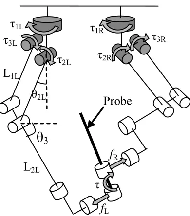
As shown in Figure 4.1, the haptic device consists of one probe, left and right articulated arms and 6 motors. The probe is the end-effector, which is connected to the bottom of two articulated arms. The left and right articulated arms consist of links and joints as shown in Figure 4.1. All joints of this haptic device are rotational. Six shaded joints in Figure 4.1 are active joints, which are driven respectively by 6 DC motors. Other joints are passive joints, whose rotations are dependent on active joints. The combined rotation of the active joints solely determines the position and orientation of the haptic probe. Torques generated by motors drive all joints and finally the haptic probe. The haptic device can generate 5-DOF force feedback on X, Y, Z axes and torque feedback on two rotational axes at the probe. There is no torque feedback on probe’s own rotational axis.
2L0=160m
L1R=150mm
L2R=180m
Active joints Passive joints 30m
Probe
L1L=180m
L2L=180m
As shown in Figure 4.1, the haptic device consists of one probe, left and right articulated arms and 6 motors. The probe is the end-effector, which is connected to the bottom of two articulated arms. The left and right articulated arms consist of links and joints as shown in Figure 4.1. All joints of this haptic device are rotational. Six shaded joints in Figure 4.1 are active joints, which are driven respectively by 6 DC motors. Other joints are passive joints, whose rotations are dependent on active joints. The combined rotation of the active joints solely determines the position and orientation of the haptic probe. Torques generated by motors drive all joints and finally the haptic probe. The haptic device can generate 5-DOF force feedback on X, Y, Z axes and torque feedback on two rotational axes at the probe. There is no torque feedback on probe’s own rotational axis.
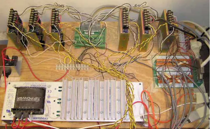
To control and provide the necessary feedback signals of the haptic device, a haptic controller system is developed for the 6-DOF haptic device, as shown in Figure 4.2. The details of the controller elements and the layout are shown in Figure 4.3 [Zhu 2003].
1 2 3 4 5 6
24V, 12A Power Supply
Counter board DB-37
110V Plug Switch 24V
Switch 5V
Bus connector
Bus connector D/A
Board Terminal
Common Ground
Input Output
Amplifiers
Amplifiers
Figure 4.3 The controller elements and layout of the 5-DOF haptic device [Zhu 2003]
Encoder (ENC-258101 2000/3CH, Chiba Precission) DC Servomotor (NC-258102, Chiba Precision) Amplifiers (A-001,Chiba Precision) D/A board (PCIDAC08, CyberResearch) Counter Board (CNT32-8M, CONTEC) CPU1 Simulation algrithms Graphic interface CPU2 Control algorthms Haptic rendering Controller
Haptic device Dual-CPU workstation
Figure 4.4 The haptic device hardware working flow
4.2.2 Kinematics analysis of the haptic force feedback device
The kinematics of the 5-DOF haptic force feedback device is analyzed based on the right and left articulated arms. Three coordinate systems are defined in this chapter, including world coordinate system Σw, left local coordinate system ΣL and right local coordinate system
ΣR, as shown in Figure 4.5. In the diagram, only the left arm is used for illustration. Right
arm can be analyzed accordingly. Figure 4.5 also defines the rotation angles of left links, such as θ1L, θ2Land θ3L. Note that movements of left arm are constrained onto a plane so
that their angles with X axis are always θ1L. When probe is moved upon the manipulation, it
will rotate around its pivot pointP, which is the midpoint of PLand PR.
Ow OL Σ w Σ L Σ R OR
Zw ZR
ZL YL XL YR YW XR X W L0 PL PR P Probe θ1L θ2L θ3L θ1L L0 L1L L2L L1L,x L2L,x L1L,y L2L,y L1L,z L2L,z L1R L2R
According to Figure 4.5, we can derive the positions of PLand PR within world
coordinate system [Zhu 2003]. The X coordinate of PL, PL,xcan be shown as follows:
x L x L x
L L L
P, = 1 , + 2 , (4.1)
where L1L,xis the L1L’s projection on X axis and L2L,x is the L2L’s projection on X axis.
x L
L1, and L2L,x can be calculated respectively by Equation (4.2) and (4.3) as,
L L
L x
L L
L1 , = 1 ⋅sinθ2 ⋅cosθ1 (4.2)
L L
L x
L L
L2 , = 2 ⋅cosθ3 ⋅cosθ1 (4.3)
Combine Equations (4.1) to (4.3), one can calculate PL,x shown as follows:
L L L L L L x
L L L
P, = 1 ⋅sinθ2 ⋅cosθ1 + 2 ⋅cosθ3 ⋅cosθ1 (4.4)
Similarly, we can obtain PL,yand PL,z. The position of PL and PR can be expressed by the
following Equations (4.5) and (4.6) respectively,
⎟ ⎟ ⎟ ⎠ ⎞ ⎜ ⎜ ⎜ ⎝ ⎛ ⋅ − ⋅ − + ⋅ ⋅ + ⋅ ⋅ ⋅ ⋅ + ⋅ ⋅ = L L L L L L L L L L L L L L L L L L L L L L L L P 3 2 2 1 0 1 3 2 1 2 1 1 3 2 1 2 1 sin cos sin cos sin sin cos cos cos sin θ θ θ θ θ θ θ θ θ θ (4.5) ⎟ ⎟ ⎟ ⎠ ⎞ ⎜ ⎜ ⎜ ⎝ ⎛ ⋅ − ⋅ − − ⋅ ⋅ + ⋅ ⋅ ⋅ ⋅ + ⋅ ⋅ = R R R R R R R R R R R R R R R R R L L L L L L L P 3 2 2 1 0 1 3 2 1 2 1 1 3 2 1 2 1 sin cos sin cos sin sin cos cos cos sin θ θ θ θ θ θ θ θ θ θ (4.6)
As shown earlier in Figure 4.5, since the pivot point P is the midpoint between PL and PR,
its position can be easily calculated as follows:
2 R
L P
P
P = + (4.7) And the haptic probe orientation rp
r can be expressed by
R L R L p P P P P r − − =
r (4.8)
τ1L Probe τ1R τ2R τ3R τ3L τ2L fL fR L1L L2L τ
θ
3 θ2LFigure 4.6 Force and torque model of the haptic device
First, we define the joint displacement vector θand the displacement of the haptic
probe prespectively by
T n
)
,
,
,
(
θ
1θ
2θ
θ
=
L
(4.9)T m
p
p
p
p
=
(
1,
2,
L
,
)
(4.10) where n and m are the variable numbers of each vector. This haptic device consists of twelvejoints, in which only the six active joints are independent. Vector θ includes the six active
joints so that n equals to 6. p represents the positions of PL and PR, which also have six
variables. Therefore, for this device, the vector θ is T
R R R L L
L, , , , , )
(θ1 θ2 θ3 θ1 θ2 θ3 and the vector
p is T
z R y R x R z L y L x
L p p p p p
p , , , , , )
( , . , , , , . According to Equations (4.5)-(4.8), p can be re-written
as a function of θ shown as follows: )
(
θ
F
p= (4.11)
Differentiating both sides of Equation (4.11) by time, one can get the following equation:
θ θ θ
θ & &
& F J
p =
∂ ∂
![Figure 4.3 The controller elements and layout of the 5-DOF haptic device [Zhu 2003]](https://thumb-us.123doks.com/thumbv2/123dok_us/1489210.1182199/50.612.155.478.68.308/figure-controller-elements-layout-dof-haptic-device-zhu.webp)