Foundation in Refilled Soil
Sagar Satish Tayade, Mukund M. Mahajan
Student of M-tech, Applied Mechanics Dept., Visvesvaraya National Institute of Technology (V.N.I.T.), Nagpur, Maharashtra, India..
Professor, Applied Mechanics Dept., Visvesvaraya National Institute of Technology (V.N.I.T.), Nagpur, Maharashtra, India.
Abstrac t: In ma jor c ities due to scarcity of the space in prime locations, the construction is even proposed on refilled areas. The refilled areas may be of natural fill or engineering fill. In engineering re fill the proper precaution is taken for the selection of the refill material and at most care is taken for the compaction too with the understanding that some construction may be ta ken in future on such areas . But this type of the filling procedure is rare ly adopted. Norma lly the filling is done by any materia l including garbage with no importance given to co mpaction; it is just dumping of the materia l in to the pits of the ground. It is always beneficia l to have foundations on engineering refilled soil. But however it is a matter of great concerned when the foundation will be proposed on such type of natural or man made refills. In this paper an attempt is made to study the raft foundation and raft with pile foundation on refilled man made soil.
Ke ywor ds: re filled soil, consolidation settlement, rafts foundation, piled ra ft foundation , SAFE software.
I. IN TRO DUC TION
In town planning system a ring road is provided wh ich acts a boundary of a developed area. Out of this boundary of ring road the waste fro m the city including organic and inorganic material are du mped in to the pits for number of years . With the growth of c ities, the area of du mping a lso becomes part of city and structures have to be constructed over this refill. The properties of this type of refill are unpredictable. Even in case of organic refill (eg. San itary landfill) the chances of settle ment is mo re due degradation of o rganic matter. Foundation over such refill may be dangerous or pile foundation or drilled piers may be provided after detailed investigation of refilled soil.
symmetric p ile configuration is adopted and throughout the refill layer the properties of refill materia l are assumed as same.
In this paper all the possible alternatives of providing foundation on refilled strata are summa rized which will serve as a guide to consider the parameters for construction of any structure on refilled strata in safe and economic way. The parametric study carried out on normal raft and piled raft using SAFE software will a lso be useful for developing and improving recent trends for analysing and designing the foundations of structures on refilled strata.
II. METHO DOLOGY
In most of the cases of refilled strata; uniform or d ifferentia l settlement of foundation is the ma jor criteria that should be given prime importance for analysis and design. Pile, raft o r cassion are the types of foundations which are recommended for the structures resting on loose or refilled strata. Raft is mostly used under these situations if it satisfies both the load and settlement criteria. If the raft alone is ab le to carry the superstructure‟s load but it fails in settlement criteria piles are introduced to reduce the settlement of the foundation [7]. Hence it is necessary to analyse raft alone even if we have to provide piled raft foundation.
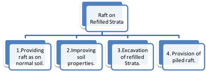
The common a lternatives to provide raft on refilled strata are:
Fig. 1 Alternatives for providing raft on refilled strata. A. Providing raft as on normal soil.
If the refill has got sufficient strength and has already consolidated under the action of e xisting overburden pressure; the soil can be treated as norma l soil and after investigation of soil p roperties the foundation can be provided as on norma l soil. Also the case may be that the depth of refill is small such as complete e xcavation of re filled strata is possible; in this case the raft can be provided on underlying norma l soil.
B. Improving soil properties.
If the strength of refilled soil could be improved by effective and economic soil improving technique, the raft can be placed on this improved soil as it is provided on nor mal soil.
C. Excavation of refilled strata.
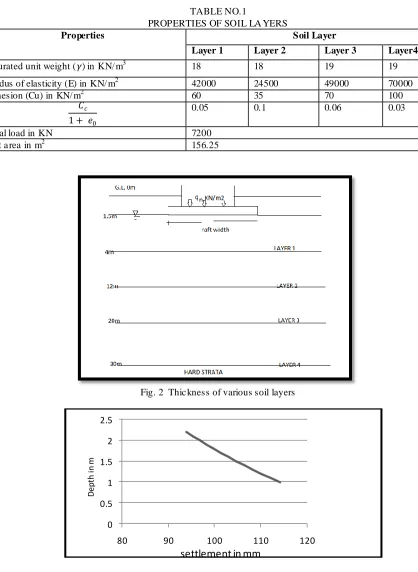
In most of the practical cases, it is not possible to completely e xcavate the refilled strata; in these cases partial e xcavation of the refill strata can be done such as the settlement of the underlying strata is w ithin permissible limit. A numerica l e xa mple is considered to know the depth of e xcavation and the corresponding settlement of the strata. The data for this exa mp le is taken fro m the video lecture of National Progra mme on Technology Enhanced Training (NPTEL), and based on the analytical formu lae for rigid foundation approach an excel progra m is prepared to find the settlement for various depths of foundations. The refill material is assumed as cohesive, hence Ske mpton‟s equation for calculating bearing capacity is used.
Proble m statement: To find out depth of excavation for pe rmissible settlement of foundation.
Raft on Refilled Strata
1.Providing raft as on normal soil.
2.Improving soil properties.
3.Excavation of refilled
Strata.
TABLE NO.1
PROPERTIES OF SOIL LA YERS
Properties Soil Layer
Layer 1 Layer 2 Layer 3 Layer4
Saturated unit weight (𝛾) in KN/ m3 18 18 19 19 Modus of elasticity (E) in KN/ m2 42000 24500 49000 70000 Cohesion (Cu) in KN/ m2 60 35 70 100
𝐶𝑐
1 + 𝑒0
0.05 0.1 0.06 0.03
Total load in KN 7200 Raft a rea in m2 156.25
Fig. 2 Thic kness of various soil layers
0 0.5 1 1.5 2 2.5
80 90 100 110 120
D
ep
th
in
m
should be satisfied. To know the a mount of consolidation settlement with respect to time for the load of superstructure, the oedometer test is reco mmended on representative refill soil sa mple . In the structures of heavy loading or uneven loadings to avoid the risk of uneven settlement, deep foundation can be adopted instead of raft foundation on partially e xcavated refilled strata.
D. Provision of piled raft.
Piles are added to raft foundation at crit ical locations so as to satisfy design criteria o f foundation . Piles are ma inly used as settlement reducers [7]. To study the behaviour of p iled raft foundation many researchers have carried out the parametric study on piled ra ft foundation [8, 11, 12]. As the piles can be terminated at h igher e levation the piled raft is considered as economica l a lternative to pile foundation [8].
The load fro m superstructure is taken partially by raft and partia lly by piles. The load fro m piles is transferred to soil partially by skin frict ion and partially by end bearing action. This phenomenon holds good for normal soil or consolidated refill soil, but in case of loose soil or unconsolidated refill soil load transfer due to skin friction may not be there; even it may impart negative skin friction. Hence it is important to study load sharing between piles and raft. To study the load sharing, the analytical approach given by Polous [2] is used in the numerica l e xa mp le. The piles are assumed to be terminated at hard strata occurring at significant depth, hence greater is the depth of raft lesser will be the pile length.
Proble m statement: To find out the load sharing between raft and piles for the fo llo wing data.
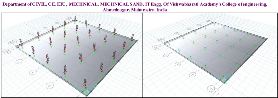
Fig. 4 Plan to show column positions and dimensions of raft Raft size = 22m x 22 m
Raft thic kness = 500mm
Er =Modulus of raft = 2E+06 KN/ m2 Ep= Modulus of pile=2E+06 KN/ m2 Soil modulus = 2.5E+04 kN/ m2 Poisson‟s ratio for raft and pile= 0.3 Poisson‟s ratio for soil= 0.45.
Fig. 4 Ra ft modelled in SAFE to show loading and pile position (piles are represented as springs)
The load sharing in this method is based on stiffness of raft and piles. The methods to find out stiffness of pile group and raft are g iven by Poulos [2] and Maharaj D.K. [12].As the depth of foundation increases the length of piles reduces hence the load sharing is calculated for va rious lengths of piles .
TABLE NO.2
SHA RING OF LOAD BETWEEN PILES A ND RA FT OF PILED RAFT FOUNDATION
Sr. no.
Length of pile in meter
Load taken by raft as % of total load
Load taken by piles as % of total load
01 14 8.69 91.3
02 12 9.54 90.46
03 10 10.94 89.06
04 8 15.23 84.77
05 6 58.1 41.89
To check the behaviour o f p iled raft foundation the para metric study is carried out using SAFE software . The parameters affecting the behaviour of piled raft a re:
1. Raft thic kness. 2. Length of piles. 3. Pile configurat ion.
To compare the settlement behaviour of simple ra ft and piled raft, both the types of foundation are modelled in SAFE software. For the soil properties the data from the soil testing report is useful. Many researchers have given empirical relations to re late the soil para meters such as modulus of e lasticity of soil and modulus of subgrade reaction with CBR [9] or with results of standard penetration test [10].
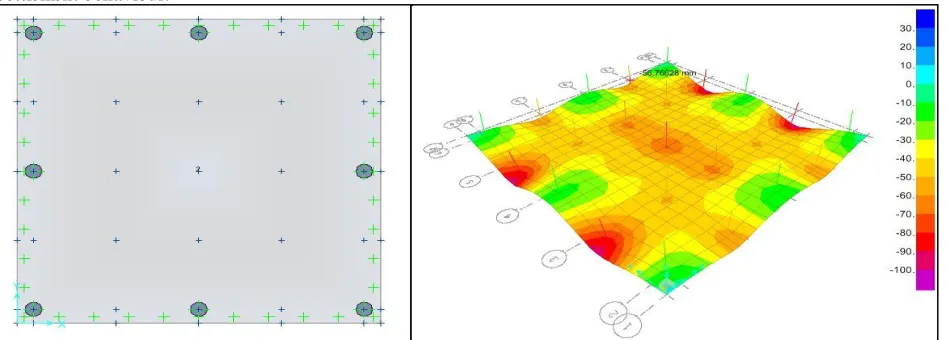
Fig. 5 Ra ft modelled in SAFE to show deformation pattern and total settlement.
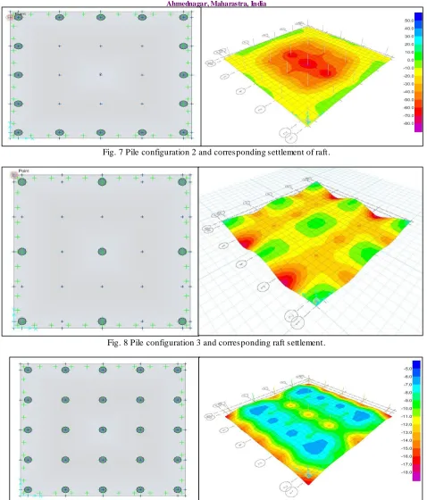
Depending on the pile capacity, nu mber of piles varies. But as in case of piled ra ft, the p iles are supposed to be used as settlement reducers and used to carry some portion of load only, d iffe rent pile configurations are prepared to study settlement behaviour:
Fig. 7 Pile configuration 2 and corresponding settlement of raft.
Fig. 8 Pile configuration 3 and corresponding raft settlement.
TABLE NO.3
COMPARISON BETW EEN SETTLEM ENT OF RAFT A ND PILED RAFT FOUNDATION
Raft without piles Configuration 1 Configuration 2 Configuration 3 Configuration 4
X direction Y direction X direction Y directio n X direction Y directio n X direction Y directio n X direction Y directio n T.S . D. S T.S . T.S . T. S D. S T S D. S T. S D. S T S D. S T. S D. S T S D. S T. S D. S T S D. S
111 - 104 - 28 - 26 - 21 - 23 - 28 - 26 - 23 - 23 - 47 64 65 39 46 18 64 38 50 29 68 45 41 13 59 33 14 9 20 3 67 20 67 2 71 25 71 7 74 24 74 6 25 16 25 34 21 7 21 1 47 20 65 2 46 25 64 7 50 24 68 6 41 16 59 34 14 7 20 1 111 64 104 39 28 18 26 38 23 27 23 45 28 13 26 33 23 9 23 3 ** T.S= Total settlement in „mm‟ at the point of observation.
D.S= Diffe rential settle ment in „mm‟ between two points of observation.
III.DISC USSION AND CONCLUSION
Among the various alternatives to provide foundation on refilled soil, the raft foundation and piled raft foundation are ma inly focused in this paper. Depending on the various factors such as age of re fill, loading on refill, material used as refill etc. the strength and other physical properties of re fill may change, hence if the refill is placed at site before soil testing, the refilled soil is also tested as norma l so il and its properties are found out, and if needed ground improve ment or partial or co mplete e xcavation of the refill is done. If the refill is required to fill at the time of construction, the quality of refill material and co mpaction method should be maintained. After conforming the satisfactory properties of re filled soil, the type of foundation i.e . raft foundation, deep foundation, or piled ra ft foundation are adopted. As settlement is one of the ma jor c rite ria to decide type of foundation and piles can be used as settlement reducers, the settlement of the piled raft is studied. If the soil is under consolidated it may impart negative skin frict ion on piles as some part of load coming on piles, hence for providing ra ft at various depths for piles e xtending up to significant level up to hard strata, (greater will be depth lesser will be length of piles) the load sharing between raft and p iles is studied and it is found that the part of total load shared by ra ft goes on decreasing with increase in length of pile hence depending on the depth of refill the proper depth selection for p iled ra ft foundation is necessary. In the next part for d ifferent pile configuration settlement is observed in SAFE software and the utility of piles as settlement reducers as compared to simp le ra ft is verified. For the larger nu mber of p iles of same dia mete r the total and diffe rential settle ments both are found to be decreasing for the same loading and same raft and soil properties . The paper has covered the study of most of the parameters which are important to provide foundation on refilled strata which can be useful to guide construction of any structure on refilled strata.
REFER ENC ES
1. IS: 2950(Part I)-1981, “ Indian standard code of practice for design and construction of raft foundations,” Bureau of Indian standards, New Delhi.
2. H. G. Poulos, “ Simplified design procedure for piled raft foundation.” ASCE. 3. Joseph E. Bowles, “ Foundation analysis and design.” 5th
edition, Mc Graw Hill Publication.
4. G. S. Kame, S. K. Ukarande, K. Borgaonkar and V.A. Sawant, “Parametric Study on Raft Foundation,” The 12th International Conference of International Association for Computer Methods and Advances in Geomechanics (IACMAG), 1-6 October, 2008.
5. J. Cho, Lee, J.H. Jeong, S. Jeong, and J.H. Lee, “The settlement behaviour of piled raft in clay soils.” Ocean Engineering 53, 2012.
6. IS:1904-1986, “ Indian standard code of practice for design and construction of foundation in soil: General requirement,” Third Revision, Bureau of Indian Standard, New Delhi.
7. N. T. Singh and B. Singh, “Interaction Analysis for Piled Rafts in Cohesive Soils.” 12th International conference of International Association for Computer Methods and Advances in Geomechanics (IACMAG), Goa, India, 2008.
8. S. J. Shukla, A.K. Desai, C.H. Solanki, “ Behavioural study of piled raft foundation in layered soil Deposit.” International Journal of advanced engineering Technology, Vol. II., 2011.
10. Reza Ziaie Moayed and Seyed Abolhassan Naeini, " Evaluation of modulus of subgrade reaction (Ks) in gravely soils based on SPT results." IAEG, Paper number 505, 2006.
11. Meisam Rabiei, “Parametric Study for Piled Raft Foundations.” EJGE, vol. 14, Bund A, 2009.