ISSN(Online): 2320-9801
ISSN (Print): 2320-9798
I
nternational
J
ournal of
I
nnovative
R
esearch in
C
omputer
and
C
ommunication
E
ngineering
(An ISO 3297: 2007 Certified Organization)
Vol. 3, Issue 8, August 2015
Enhanced Bandwidth Proximity Coupled
Equilateral Triangular Microstrip Antenna
Loaded with Horizontal Rectangular Ring Slot
Mahesh C P
1, P M Hadalgi
2Research Student, Department of PG Studies and Research in Applied Electronics, Gulbarga University, Kalaburagi, Karnataka, India1
Professor, Department of PG Studies and Research in Applied Electronics, Gulbarga University, Kalaburagi, Karnataka, India2
ABSTRACT:In this communication proximity coupled equilateral triangular microstrip antenna consisting a horizontal rectangular ring shaped slot for quad band operation is designed and its performance is calculated with reference to conventional antenna. The proposed antenna operates between 2.71 to 8.66 GHz at four different frequency points. The antenna shows enhancement in bandwidth with broadside radiation characteristics has been achieved. The design concept of the antenna is given and experimental results are presented and discussed. This antenna will be useful for IMT, WLAN (Wireless local area network) and SAR (Synthetic aperture radar).
KEYWORDS: Equilateral triangular microstrip antenna, Proximity coupled, Horizontal rectangular ring slot, Bandwidth.
I. INTRODUCTION
In these days, there is a very big demand of microstrip patch antennas for use in mobile and wireless applications due to of its very cheap in cost, easily available in market, light weight and compact in size. Also the design and fabrication process of antennas is very simple and their production is also easy. There are plenty of varieties patch designs available but the square, rectangular, circular and elliptical shapes are most frequently used. In this paper we use equilateral triangular patch antenna. But these microstrip antennas have some disadvantages in low bandwidth, low gain and also low in efficiency [1-7]. There are many ways by which we can enhance the bandwidth of microstrip antennas. In order to enhance the bandwidth of a patch antenna, several techniques have been proposed, such as, by using thick substrates [8], cutting slots on the patch [9], by using aperture coupled stacked patch antennas [10], coaxial feeding technique [11], stacked patch fed through microstrip line technique [12], proximity coupled feeding techniques [13-15] etc.
The main achievement of this paper is to present the enhancement bandwidth of microstrip antenna using horizontal rectangular ring slot loaded on the patch of proximity coupled equilateral triangular microstrip antenna. The experimental result indicates that when inserting slot on the conventional microstrip antenna which gives a wide operating bandwidth and good radiation patterns.
II.
A
NTENNADESIGNCONSIDERATIONThe proposed antennas are developed using software AutoCAD to achieve better accuracy and are fabricated on low cost glass epoxy substrate material of thickness h=0.32 cm with dielectric constant of Ɛr = 4.2 and tan ð = 0.02. The
ISSN(Online): 2320-9801
ISSN (Print): 2320-9798
I
nternational
J
ournal of
I
nnovative
R
esearch in
C
omputer
and
C
ommunication
E
ngineering
(An ISO 3297: 2007 Certified Organization)
Vol. 3, Issue 8, August 2015
The Fig. 1 shows geometry of proximity coupled equilateral triangular microstrip antenna (PCETMSA). The proposed antenna is designed for the frequency of 3 GHz using the relations present in the literature for the design of equilateral triangular microstrip antenna. The equilateral triangular microstrip patch antenna is made up of side length „a‟ cm over a substrate S1 with substrate thickness „h‟ cm. The value of „a‟ is obtained from equation (1),
(1)
Figure.1. Geometry of PCETMSA
where, C is the velocity of light and fr is the resonating frequency of the proposed antenna. The microstripline
feed of length Lf and width Wfis etched on the top surface of substrate S2. The substrate S2is placed below substrate S1
such that the tip of the feedline and the center of the radiating patch coincide one over the other. The bottom surface of the substrate S2 acts as the ground plane. The h and Ɛr of substrates S1and S2are same. This type of feed technique is
also called as the electromagnetic coupling scheme. The main advantage of this feed technique is that it eliminates spurious feed radiation and provides very high bandwidth due to overall in the increase in the thickness of the microstrip patch antenna.
Figure.2. Geometry of HRRSPCETMSA Figure.3. Top view of HRRSPCETMSA
ISSN(Online): 2320-9801
ISSN (Print): 2320-9798
I
nternational
J
ournal of
I
nnovative
R
esearch in
C
omputer
and
C
ommunication
E
ngineering
(An ISO 3297: 2007 Certified Organization)
Vol. 3, Issue 8, August 2015
Table. 1 Designed specifications of the proposed antennas
Antenna Specifications Dimensions in cm
Side length of equilateral triangle (a) 2.70 Length of the feedline Lf 2.5 Width of the feedlineWf 0.633 Length and width of the ground plane
(Lg and Wg) 4.6
Thickness of substrate S1 and S2
(h1+h2) 0.64
w 1.2
x 0.8
y 0.8
z 0.4
III.RESULT AND DISCUSSION
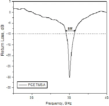
The impedance bandwidths over return loss less than -10 dB for the proposed antennas are measured. The measurements are taken on Vector Network Analyzer (Rohde & Schwarz, German make ZVK Model No. 1127.8651). The variation of return loss versus frequency of PCETMSA is as shown in Fig. 4. From the figure it is clear that, the antenna resonates at f1=2.71 GHz which is much closer to the designed frequency of 3 GHz and hence the validates the
design. From this graph, the experimental impedance bandwidth is calculated using the formula (2),
𝐵𝑊 = 𝑓2−𝑓1
𝑓𝑐 × 100% (2)
where, f2 and f1 are the upper and lower cut off points of resonating frequency when its return loss reaches -10 dB
and fc is a center frequency between f1 and f2.The PCETMSA resonates at 3GHz with impedance bandwidth of 6.97%
(2.91GHz - 3.12GHz).From the Fig. 5, it is found that the HRRSPCETMSA resonates at quad bands offrequencies f1=
2.71 GHz (2.66GHz -2.77GHz), f2= 4.72 GHz (4.30GHz - 5.27GHz), f3= 7.06 GHz (6.99GHz -7.17GHz) andf4= 8.66
GHz (8.13GHz-10GHz), so the overall band width measured for HRRSPCETMSA is 48.45%. The proposed antenna is compared with conventional microstrip antenna. All the results are reported in Table. 2.
ISSN(Online): 2320-9801
ISSN (Print): 2320-9798
I
nternational
J
ournal of
I
nnovative
R
esearch in
C
omputer
and
C
ommunication
E
ngineering
(An ISO 3297: 2007 Certified Organization)
Vol. 3, Issue 8, August 2015
Figure. 5. Variation of Return Loss v/s Frequency of HRRSPCETMSA
Tabel. 2. Results of all the proposed antenna
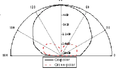
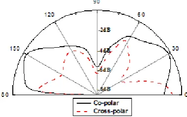
The X-Y plane co-polar and cross-polar radiation patterns of PCETMSA and HRRSPCETMSA are measured at their resonating frequencies and are shown in Fig.6 to Fig.10. For the measurement of radiation pattern, the antenna under test (AUT) i.e., the proposed antennas and standard pyramidal horn antenna are kept in far field region. The AUT, which is receiving antenna, is kept in phase with respective transmitting pyramidal horn antenna. The power received by AUT is measured from -00 to +3600 with the step of 100. These figures indicate that the antennas show broad side radiation characteristics. From these figures it is clear that, there is reduction in back lobes and broader side in radiation characteristics.
Figure. 6. Radiation pattern at 3 GHz
Antenna Resonant Frequency(G
Hz)
Return loss (dB)
Bandwidth in (%)age
Overall Bandwidth in
(%)age
PCETMSA 3 -30.26 6.97 6.97
HRRSPCETMSA
2.71 4.72 7.06 8.66
-13.39 -15.27 -10.42 -21.80
4.05 20.27
2.54 21.59
ISSN(Online): 2320-9801
ISSN (Print): 2320-9798
I
nternational
J
ournal of
I
nnovative
R
esearch in
C
omputer
and
C
ommunication
E
ngineering
(An ISO 3297: 2007 Certified Organization)
Vol. 3, Issue 8, August 2015
Figure. 7. Radiation pattern at 2.71 GHz
Figure. 8. Radiation pattern at 4.72 GHz
Figure. 9. Radiation pattern at 7.06 GHz
ISSN(Online): 2320-9801
ISSN (Print): 2320-9798
I
nternational
J
ournal of
I
nnovative
R
esearch in
C
omputer
and
C
ommunication
E
ngineering
(An ISO 3297: 2007 Certified Organization)
Vol. 3, Issue 8, August 2015
IV.CONCLUSION
Experimental results indicate that impedance bandwidth of the conventional antenna can be significantly improved by employing horizontal rectangular ring slot on the patch i.e., HRRSPCETMSA resonates for quad bands and is quite good in enhancing the bandwidth with broadside radiation patterns at the resonating frequencies, which makes the antenna useful for IMT, WLAN (Wireless local area network) and SAR (Synthetic aperture radar) applications.
REFERENCES
1. C. A. Balanis,“Antennas theory analysis and design”, 2nd edition, John wiley&sons. Inc, 1997. 2. Kin – Lu Wong,“Compact & broadband microstrip antenna”, John wiley& Sons. Inc, 2001. 3. Kumar, G. and K. P. Ray,Broad band microstrip antennas, Artech House, USA, 2003.
4. PratibhaSekra, SumitaShekhawat et.al, “Design of circularly polarized edge truncated elliptical patch antenna with improved performance”, Indian Journal of Radio and Space Physics, Vol. 40, pp. 227-233, August 2011.
5. Jolly Rajendran, RakeshPeter and KP Soman, “Design of circular polarized microstrip patch antenna for L Band”, International Journal of Electronics Signals and Systems (IJESS), Vol. 1, Issue. 3, pp. 47-50, 2012.
6. Monika Kiroriwal and SanyogRawat, “Improvement in radiation parameters of rectangular microstrip patch antenna”, International Journal of Engineering Research and General Science, Vol. 2, Issue. 6, pp. 393-397, Oct- Nov 2014.
7. GovindAgarwal, AtifRizwan, Rajeev Kumar Singh and RajarshiSanyal, “Bandwidth enhancement of triangular microstrip antenna using dual stub”, International Journal of Scientific and Engineering Research, Vol. 4, Issue. 4, April 2013.
8. Ali A. Dheyab Al-Sajee and Karim A. Hamad, “Improve bandwidth rectangular patch antenna using different thickness of dielectric substrate”, Vol. 6, Issue. 4, pp. 16-21, April 2011.
9. Y. Li, Y. Liu and S. Gong, “Microstrip antenna using ground-cut slots for low RCS with size miniaturization techniques”, Progress In Electromagnetics research Letters, Vol. 1, pp. 211-220, 2008.
10. Gunjan and AmanpreetKaur, “Dual band aperture coupled stacked microstrip patch antenna forwlan”, International Journal of advanced research in Electrical, Electronnics and Instrumentation Engineering”, Vol. 3, Issue. 7, pp. 10820-10826, July 2014.
11. D.K. Srivastava, J.P. Saini, D.S. Chauhan,“Wide band electromagnetically coupled coaxial fed slot loaded stacked patch antennas”, (IJEST-NG), Vol.3, PP 154-159, 2011.
12. H. F. AbuTarboush , H. S. Al-Raweshidy , and R. Nilavalan ,“ Bandwidth Enhancement For Microstrip Patch Antenna Using Stacked Patch And Slot,” IEEE , 2009.
13. Amit Kumar, JaspreetKaur and Rajinder Singh, “Performance analysis of different feeding techniques”, International Journal of Emerging Technology and Advancsd Engineering”, Vol. 3, Issue 3, PP.884-890, March 2013.
14. D. M. Pozar and B. Kaufman, “Increasing the bandwidth of a microstrip antenna by proximity coupling,” Electron.Lett., vol. 23, no. 8, pp.368– 369, Apr. 1987.