Active and Reactive Power Enhancement of
Electrical Distribution Network using FLC
Nikhil Kumar Jha
1, Prof. Ashutosh Rai
2M. Tech. Scholar, Dept. of Electrical and Electronics Engineering, Iasscom Fortune Inst. of Technology, Bhopal, M.P. India1
Assistant Professor & Head of Dept., Dept. of Electrical and Electronics Engineering, Iasscom Fortune Inst. of Technology, Bhopal, M.P. India2
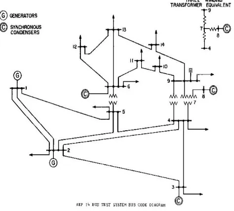
ABSTRACT: Electrical Distribution System is the back-bone of the power system. Acting as the final supplier of electricity to the consumers, electrical distribution system is prone to a number of contingencies. In such a condition, restoration of the distribution system within a certain time frame is the top priority. While restoring the system, care should be taken to keep the system parameters within limits. Keeping in view of all the parameters and complex nature of the distribution system, makes its restoration a composite problem. A Single line diagram of the IEEE 14 Bus standard system is used in this paper with load assumed to be represented by constant impedance. The size and installation location for load margin improvement and price discussions are addressed. The IEEE 14 Bus is modeled using the elements of Simulink. The effectiveness of the proposed controllers, the improvements in power quality and in voltage profile is demonstrated. In the simulation, the results of the proposed model for the Fuzzy Logic Controller based STATCOMare determined.
KEYWORDS: - IEEE 14 bus System, Fuzzy Logic Controller, STATCOM Technology, MATLAB Simulink
I. INTRODUCTION
software. Through the high-voltage transmission line, the power is finally delivered to the consumer through the heavily interconnected electrical distribution system network. All the individual consumers get benefited from this vast infrastructure of distribution system, which is undoubtedly one of the power system final stage. The power from the transmission system is step down by the distribution system which normally ranges from 2 kV and 33 kV with the help of interconnected transformers [6]. This medium voltage power flow through the primary distribution lines to the transformers installed at the customer's location. The voltage is again lowered to the usable voltage required for the home appliances. In this way many consumers are served by these secondary lines. The connections to the consumers are also dependent on the demand for the electricity. The big commercial consumers are sometimes
II. DISTRIBUTIONSYSTEMDESIGNS
All over the world a number of distribution systems is designed and used. These systems can broadly be characterized as under Loop, Radial and Network distribution systems. These systems are discussed in the next subsection.
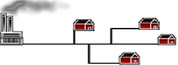
Loop Distribution System
A system in which the consumers are connected through the power supply in a circular way is characterized as loop system. Alternatively, there is an extra power source is connected within the system in such a way that when any contingency occur on the system, the line switches could be used; which are placed at strategic location; to energize the consumer from any direction. In case one of the power sources is failed the other one could be used as a backup power supply. A loop network uses a number of switches which are used at many locations, making it an expensive kind of power distribution system. The loop system is better in terms of reliability since the consumers can be energized with a minimum time delay. When the fault occurs in the lines, a minimum number of consumers get affected by the restoration process. The reliability factor of loop system just overshadows its expensive characteristic where the demand is of least timing for power supply interruption [7].
Figure 1: Loop distribution system
Radial Distribution System
For the areas where the population is very thin i.e. the numbers of consumers are less radial distribution system is the most appropriate choice. The single power source is used in the radial system for a particular area. In case of fault occurring on the system the entire power supply of the area gets interrupted [8].
Network Distribution System
The most complicated and interlocked looped systems are network distribution system. The electricity is supplied from more than a single source. This feature of the network distribution system added to the reliability of the power supply to the consumer. Also, because of this feature it is the most expensive distribution system. The high load density areas like industries, municipality etc. usually use network distribution system [9].
Figure 3: Network distribution system
After the analysis of the major categories of the electrical distribution system the idea is drawn about its complexity. Being a highly labyrinth structure and connected through a number of devices, electrical distribution system is the end mean to supply electricity to the consumer. The loads which are connected to the highly meshed electrical distribution system are of different characteristics e.g. either lagging/leading power factor. The connectivity of these loads with power system is through the different devices like transformers, electrical fuses, line switches, circuit breakers, tie switches etc. Since distribution system is designed in such a way that it covers all the consumers in a given area which are usually described as zones. These consumers are connected within the zone by line switches through which they can be connected or isolated as required. There are a number of zones exist within an electrical distribution system. These zones are connected with each other with the help of tie-switches. To switch the load from one zone to another the switching i.e. opening or closing operation of line switch and tie switch took place respectively. For the switching to be successful the loads connected to the outgoing feeder having contingencies like fault on the lines and overloading of feeders, should be selected in such an intelligent way that the feeder which is going to supply these loads should not get overloaded or meet with any other fault. Due to the number of uncertainties occur during the loading and unloading of a distribution feeder with vague data, advantage is taken by implementing various techniques which works in such a scenario. Various methods have also been formed on the basis of the past experience of the operators and experts working in the distribution system field.
III. PROPOSEDMETHODOLOGY
Figure 4: Simulink Model of STATCOM
During steady-state operation the STATCOM control system keeps the fundamental component of the VSC voltage in phase with the system voltage. If the voltage generated by the VSC is higher (or lower) than the system voltage, the STATCOM generates (or absorbs) reactive power. The amount of reactive power depends on the VSC voltage magnitude and on the transformer leakage reactance. The fundamental component of VSC voltage is controlled by varying the DC bus voltage.
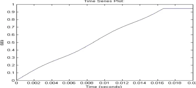
Figure 5: Output Waveform of the STATCOM
system. It also leads to the increase in the system overall power loss which lead to the financial loss to the utility & consumers. It is estimated that at distribution system level due to line losses about 5-13% of the overall generated power is wasted. Hence, to protect the system from the overload contingency the preventive measure should be taken in the intelligent way so that the end result will show a better voltage profile with an overall reduction in power loss.
Figure 6: Flow Chart of IEEE 14 Bus Systems
IV. SIMULATIONRESULT
To get the better result as compared to PI controller based STATCOM we use Fuzzy Logic Controller STATCOM. In the study we see that FLC based STATCOM provides better result as well it is more reliable in uncertain cases like varying loads and fault conditions. We’ll discuss these cases later on.
Figure 7: Control scheme of FLC based STATCOM
Figure 8: Simulink result of active and reactive power in of IEEE 14-bus system with FLC based STATCOM
The diagram shows the active and reactive power waveform of phase A. Active power waveform is a pure sinusoidal which was distorted in case of PI controller. Thus active power waveform has been clearly improved after applying FLC in STATCOM for control purpose. Reactive power is also slightly increased in this case.
Figure 9: Voltage v/s time plot of bus-1 of IEEE 14-bus system with FLC based STATCOM
Table I: Comparison Result
V. CONCLUSION
a small scale generation, connected to distribution system generating power from renewable or non-renewable energy sources using both modern and conventional technologies. Recently, use of distributed generation is being encouraged because of its numerous benefits such as reduced system loss, voltage profile improvement, enhanced system reliability, relieved transmission and distribution congestion etc.
REFERENCES
[1] M. Venkateswara Reddy, Sishnu Prasad Muni and A. V. R. S. Sarma, “Enhancement of Voltage Profile for IEEE 14 Bus System with Inter line
Power Flow Controller”, 2016 Biennial International Conference on Power and Energy Systems: Towards Sustainable Energy (PESTS E).
[2] A. Wiszniewski, "New criteria of voltage stability margin for the purpose of load shedding", IEEE Transactions on Power Delivery, Vol. 22,
No.3, ,July 2007 pp. 1376-1370.
[3] Gyugyi, L, Fuerte-Esquivel, C. R., Acha, E., Tan, S.G., Rico, 1.1., 'Efficient object oriented power system software for the analysis of
large-scale networks containing facts controlled branches', IEEE Trans. Power System 3(2) 1998, pp- 464-472.
[4] Hingorani, N.G., Gyugyi, “Understanding facts concepts and technology of flexible ac transmission systems”, Institute of Electrical and
Electronic Engineers, New York, 2000.
[5] K. A. Corzine, M. W. Wielebski, F. Z. Peng, and 1. Wang, "Control of cascaded multilevel inverters," IEEE Trans. power electron, vol. 19,
no.3, May 2004,pp. 732-738.
[6] L. A. Zarate, C. A. Castro, 1. L. Ramos, and E. R. Ramos, "Fast computation of voltage stability security margins using nonlinear 158
programming techniques", IEEE Transactions on Power Systems, Vol. 21, No.1" February 2006,pp. 19-22.
[7] J. Zhang, 1. Y. Wen, S. 1. Cheng, and 1. Ma, "A Novel svc allocation method for power system voltage stability enhancement by normal forms
of diffeomorphism", IEEE Transactions on Power Systems, Vol. 22, No.4, pp. 1819-1822,
[8] S. Gerbex, R. Cherkaoui, and A. 1. Germond, "Optimal location of facts devices to enhance power system security", IEEE Power Tech
Conference, Bologna, June 2003, pp.l -7.
[9] A. E. Hammad, “Analysis of Power System Stability Enhancement by Static VAR Compensators”, IEEE Trans. PWRS, 1986.
[10] K. R. Padiyar and R. K. Varma, “Damping Torque Analysis of Static VAR System Oscillations”, IEEE Tran. PWRS, 1991.
[11] A. R. Messina, O. Begovich, and M. Nayebzadeh, “Analytical Investigation of the Use of Static VAR Compensators to Aid Damping of
Interarea Oscillations”, Electric Power Systems Research, 1999.
[12] M. Parniani and M. R. Iravani, “Optimal Robust Control Design of Static VAR Compensators”, IEE Proc. Genet. Transm. Distrib., 1998.
[13] M. A. Abido, “Analysis and Assessment of STATCOM-Based Damping Stabilizers for Power System Stability Enhancement”, Electric Power
Systems Research, 2005.
[14] N. C. Sahoo, B. K. Panigrahi, P.K. Dash, and G. Panda, “Multivariable Nonlinear Control of STATCOM for Synchronous Generator
Stabilization”, Int. J. of Electrical Power and Energy Systems. 2004.
[15] L. Cong and Y. Wang, “Coordinated Control of Generator Excitation and STATCOM for Rotor Angle Stability and Voltage Regulation