GSM Based Smart Home Using Arduino
M S Dharani Priya
1, J Kasthuri
2, M Kanniyammal
3, K Sneha
4Department of Electrical and Electronics Engineering, Velammal College of Engineering and Technology, Madurai,
Tamil Nadu, India1234
ABSTRACT: In this study we show the personified use of smart mobiles in achieving smart homes, home security and identifying the load status.Nowadays, mobile phone has become man’s companion. Hence, the use of mobile phones is personified so that a smart home can be achieved. A smart home is a home that uses Information Technology to monitor the user needs and to control the home appliances accordingly. Though Smart Home is a complex technology, it is developing because it provides efficient ways to communicate with outside world and home security. In this paper, the home appliances are controlled by sending a simple text message from the installed mobile phone. Home Automation is achieved using GSM (Global System for Mobile Communication) technology. GSM is the module that communicates with the user, anywhere in the world via text messages and operates the home appliances accordingly. This controller is extremely useful and handy in the cases when we have to control the ON and OFF switching of the devices but there is no availability of wired connection to that place. The microcontroller would then control the device based on the information given to it. Home security application of the system uses a vibration sensor that vibrates when the appliance is mishandled or when it realizes anydanger and results in alarming of mobile phone.. The system uses the GSM text message not only to control the appliance but also to identify the status (ON/OFF) of the system at the moment. Thus, this project is expected to save time, effort and achieve Home Automation, home security and easy handling.
KEYWORDS: Global System for Mobile Communication (GSM), home automation, home security, short message service (SMS), vibration sensor, MAX232, Arduino software.
I. INTRODUCTION
The rapid growth of wireless communication and the rising usage mobile phones are the main motivations behind the idea of the paper. Every individual in these days owns a mobile phone and hence the controlling features can be easily accessed using a mobile phone. This makes the system more handy and the user need not search for other devices or go for switch boards to operate the appliances in home.A smart home enables the home owner to monitor and control his/her home appliances with least efforts. If that is the case, GSM technology provides a simple solution. The appliances of the home must be secured and safe or even if it realises any danger the user must be alerted immediately. For such security purposes, a vibration sensor works which makes the mobile vibrate when the appliances are mishandled.
In order to make the smart home more efficient, we also concentrated on the security of the home. The home security is achieved using a vibration sensor. This sensor senses if there is any mishandling of the appliance or if there is any danger (smoke, theft etc.) and results in alarming of the mobile phone as a sign of alerting the user.In our proposed paper the system is wireless and it controls the loads using the user’s mobile headset thus making the system more adaptable and cost effective
II. SYSTEM DESCRIPTION
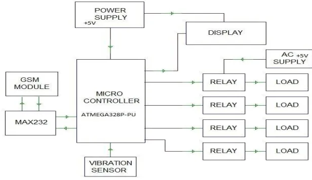
The system has two main parts: hardware and software.The hardware part mainly consists of a 8-bit micro-controller(ATMEGA328P-PU) which is based on stand-alone embedded system, GSM module and vibration sensor. The other parts of hardware system are MAX232, relays, loads and a GSM SIM. The GSM SIM communicates with the user via text messages with a pre-defined format. This messages are known as GSM SMS. The MAX232 is a device that acts as a buffer and amplifier according to the need. The software part consists of Arduino software using which the functions are programmed. The micro-controller consists of the programming part of the system. Thus, the micro-controller(ATMEGA328P-PU) is the heart of the system containing the core arduino programs of the system.
HARDWARE USED:
The hardware parts used in the system are explained as follows:
A. MICRO-CONTROLLER:
The micro-controller used is ATMEGA328P-PU. The micro-controller consists of the arduino codes in which the function of the system is defined. Thus, the micro-controller is referred as the heart of the system.
B. MAX232:
MAX232 is the part of the circuit that is used as a buffer and an amplifier according to the need at the moment. The MAX232 acts as a buffer when it is to convert the GSM SMS to signal and send the signal to micro-controller and acts as an amplifier when it receives the signals sent by the micro-controllerand sends it to the GSM module.
C. VIBRATION SENSOR:
Vibration sensor is the sensor that is used for security purpose. Vibration sensor can measure and analyze the displacement, linear velocity and acceleration. The sensor makes the mobile vibrate if there is any mishandling of any appliance or if the appliance realizes any danger like smoke, fire etc.. The sensor detects any danger by the changes in the vibrations of the system and automatically sends the signals to the alarm boxes of the installed mobile phone and thus the mobile alarms alerting the user about the abnormal occurrences in the system. Using the vibration sensor any small changes occurring in the system is immediately informed to the user through the alarming of mobile phones.
D. POWER SUPPLY:
The power supply required by the system is +5V. The actual power supply obtained (230V) is stepped down using a step down transformer to about 9 volts. Then the obtained 9V is again stepped down to +5 V using a darlington circuit.
Figure 2: POWER SUPPLY DIAGRAM
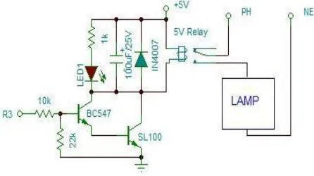
E. RELAY:
A relay is a switching device that turns the circuit ON/OFF according to the instruction. The instruction is received to the relay by the micro-controller and the function of the relay is to operate the load accordingly. The system uses a +5V AC relay.
F. DISPLAY:
Display screen displays the status of the system to the user on the user request to the micro-controller. When the user sends request SMS to the micro-controller, it receives the request and sends the user the load status. Thus, the status of the respective load is displayed in the display screen.
G. LOAD:
Any type of load can be connected and controlled by the system.
H. GSM MODULE:
A GSM (Global System for Mobile Communication) is a digital mobile telephony system. It is a digital cellular technology that is used for transmitting mobile voice and data services. GSM is the most commonly preferred module for wireless communication over the other two, TDMA and CDMA. GSM works in digitizing and compressing the data and sending it down to a channel with two other streams of user data, each in its own time slot. It operates in a frequency band of 900 to 1800 mhz. It uses narrow band time division multiple access (TDMA) technique for transmitting signals. GSM can carry upto 64 kbps to 120 mbps of data rates.
The GSM module in this paper is used for two functions: one is receiving the GSM SMS from the user mobile and sending the message to the buffer and the other function is receiving the data sent by the amplifier and sending it to the display screen for the user reference.
SOFTWARE USED:
The software used in the system is Arduino. The arduino language is chosen for its open source availability. This open source availability allows the user to write the code and install to the micro-controller. The programming is written in the micro-controller of the system. Arduino programs can be written using C, C++ or JAVA language. The arduino programs can be compiled and uploaded to the arduino board in a single click. The programs that are written using arduino boards are called arduino sketches. The arduino sketches should be written in text editors and are to be saved with extension “.ino”.
Editing or replacing the codes in future is possible.
Arduino uno is a language that is based on the ATMEGA328 micro-controller board. It has 14 digital I/O pins each of specified functions. The arduino program consists of every instructions in a step by step model that is required for the proper functioning of the system. Once if the arduino program is installed to the micro-controller, it means that the micro-controller is completely ready for the functioning and it can be simply connected to the other devices of the system and start working.
The micro-controller, ATMEGA328 has upto 32 kb of flash memory for storing the codes hence it supports even larger codes and complex functioning.
The arduino software contains a serial monitor which allows simple text data to be sent to and from the arduino board. Arduino has the ability to sense the environment by receiving inputs from various sensors and affect the surroundings by its automatic functions. Thus, the same logic is used in this paper
by making the micro-controller perform according to the received instruction by the user.
III. FUNCTIONING OF THE SYSTEM
A. CONTROLLING HOME APPLIANCES USING MOBILE PHONE:
The home appliances are controlled by using the
GSM module whereas the GSM acts as the communication device between the user and the system. The command that the user wants to give the system is sent as a text message to the GSM SIM. This text message is of a pre-defined format and these messages are called GSM SMS.
Once the GSM SMS is sent to the GSM SIM
that is installed to the system, it is received by the GSM module and the GSM SMS is converted to machine language signals by MAX232, which acts as a buffer at the moment. The converted signals are sent to the micro-controller and the micro controller is supplied with a +5V AC power. The micro-controller (ATMEGA328P-PU) analyses the signal and compares with the instructions programmed in the arduino program of the micro-controller. The Micro-controller sends the signal to the relay and the relay switches ON/OFF the loads according to the received command.
B. HOME SECURITY:
The home security is as important as the home control and for this purpose, a vibration sensor is used. The main function of the vibration sensor is to analyse the vibrations of the circuit and alarm the user if it senses any abnorma activities in the system so that the user is immediately informed about the happenings of the system.
The vibration sensor constantly analyses the vibrations and movements of the appliances in the system. Once, if there is any change in the vibrations of the system, the sensor sends the signal to the micro-controller. The micro-controller analyses with the arduino program for the next instruction. Here, the micro-controller and the display screen gets the power supply of +5V AC. The signals from the micro controller is sent to the user’s mobile headset’s display screen and immediately the mobile alarms as a sign of alerting the user about the abnormalities in the system.
The security method used here is a simple circuit, economically more feasible and is more efficient since it communicates with the user within seconds.
C. IDENTIFY THE LOAD STATUS:
The user may tend to forget if the load is ON or OFF at the moment when the user is away from the load. In that cases, the user may want to know the status of the load. For such purposes, the user may send a request sms to the system indicating that the user wants to know about the load status.
When the request SMS is sent to the system, it is received by the GSM module and the MAX232 acts as a buffer and converts the SMS to signals enabling the machine to understand. The signals are sent to the micro-controller and the micro-controller analyses with the arduino programs and looks for the status of the relay. The load status is determined and the signals from the micro-controller is sent to the MAX232 where the signals are amplified and sent to the GSM module. Thus, sending the status as a text message to the user’s mobile enabling the user to know the status of the load at the moment.
IV. FUTURE IMPROVEMENTS
V. CONCLUSION
In this paper, we discussed about enabling smart home by controlling the home appliances with the mobile phone from anywhere in the world using GSM technology. The simple and efficient way for home security is achieved using a vibration sensor. The user will be able to identify the status of the load from anywhere. The main advantage is that there is no specifications regarding the operating system of the user’s mobile phone. The user may use android, windows, ios or even a simple basic model to send the GSM SMS.
REFERENCES
[1] Delgado, A. R., Picking, R., & Grout, V. (2006) Remotecontrolled home automation systems with different network technologies. Proceedings of the 6th International Network Conference (INC 2006), University of Plymouth, 11-14 July 2006, pp. 357-366. Retrieved from
http://www.newi.ac.uk/groutv/papers/p5.pdf
[2] Jawarkar, N. P., Ahmed, V., Ladhake, S. A. &Thakare, R. D. (2008). Micro-controller based Remote Monitoring using Mobile through Spoken Commands. Journal Of Networks, 3(2), 58-63. Retrieved From http://www.academypublisher.com/jnw/vol03/no02/jnw03025863.pdf
[3] Potamitis, I., Georgila, K., Fakotakis, N., &Kokkinakis, G. (2003). An integrated system for smart-home control of appliances based on remote speech interaction.EUROSPEECH 2003, 8th European Conferenceon Speech Communication and
Technology, pp. 2197-2200, Geneva, Switzerland, Sept. 14,2003. Retrieved
fromhttp://www.wcl.ee.upatras.gr/ai/papers/potamit is14.pdf
[4] Alkar, A. Z., & Buhur, U. (2005). An Internet Based Wireless Home Automation System for Multifunctional Devices, IEEE Consumer electronics,51(4),1169-1174. Retrieved fromhttp://www.thaieei.com/embedded/pdf/Automation/2002 2.pdf
[5] Ciubotaru-Petrescu, B., Chiciudean, D., Cioarga, R., &Stanescu, D. (2006). Wireless Solutions for Telemetry in Civil Equipment and Infrastructure Monitoring.3rd Romanian-Hungarian Joint Symposium on Applied Computational Intelligence (SACI) May 25-26, 2006 retrieved From http://www.bmf.hu/conferences/saci2006/Ciubotaru.pdf
[6] Sedra and Smith, Microelectronic Circuits, fourth edition, Oxford University Press, 1998 [7] R.S. Sedha, 2002. A Text Book of Applied Electronics, S. Chand andCompany Ltd., New Delhi. [8] Theodore S. Rappaport, Wireless Communications, second edition, PHI, New Delhi
[9] Internet Sources