Solar Based Improved Active Power Filter
Performance for Renewable Power
Generation System
Pardha Saradhi Ch1, D Thirupathi Rao2 , D Sekher Babu3
Associate Professor, Dept. of EEE, St.Mary’s Group of Institutions Guntur Chebrolu (V&M), A.P, India
M.Tech Scholar, Dept. of EEE, St.Mary’s Group of Institutions Guntur Chebrolu (V&M), A.P, India
Asst. Professor, Dept. of EEE, St.Mary’s Group of Institutions Guntur Chebrolu (V&M), A.P, India
ABSTRACT: Implementation of renewable energy resources is a big challenge in electronic circuits and also especially in solar cells it is a MODERN challenge in this project active power filters implementation with the four leg Inverter Voltage source inverter using predictive controller scheme is presented. as we know that the voltage source inverter allows the compensation of current harmonic components now a days for a modern power systems a big objective is to control the current control implementation from harmonics in this project a solar cell is made for this voltage source converter and powered after that the compensation performance of the power filter as shown in the transient operating condition is demonstrated through simulation results.
KEYWORDS:ACTIVE POWER FILTER, CURRENT CONTROL, FOUR-LEG CONVERTERS, PREDICTIVE CONTROL.
I.INTRODUCTION
by US government call ECBC which is concentrating about the building energy consumption in that building power consumption totally about the LED lights that means carbon fluorescent emission of carbon dioxide and carbon in atmosphere leads to reduction of oxygen levels and some other things so due to that in future a human lost his presence or he need to have an additional arrangements to his body like a different suits to control the temperature in future survival of human is also a big task so that's why Abbott advancements to the power systems we are implementing renewable energy resources like only solar cells everywhere solar cells has proven the perfect alternate to the power generation in this project also I am presenting renewable energy generation effects and its power quality due to its non-linearity solar possession plants and wind generation brands must be connected to the grid through the high power static pulse width modulation converters why because the traditional converter is pulse width modulation from the starting of the power electronic development and thyristor and easy BTE converters Power Electronics switches only pulse width modulation is the following technique to this is the new scenario in power system distributions will require more sophisticated composition techniques all through the active power filters implemented with three phase 4 login waters have already been presented in the technical literature the primary contribution of this paper is about to predictive control algorithm which is designed and implemented specifically for this application so coming to creative current controller is it good task and application for electronic circuits which are running basic the power electronic family devices . In order to improve the quality of the power injected into a grid, this paper presents a model predictive control strategy for three-phase four-leg grid-tied inverters. For the convenience of optimization, the discrete-time model of the inverter in which duty ratios are modelled as continuous control variables is investigated. A current tracking error oriented cost function is employed as a criterion to optimize duty ratios of the inverters
II.PREDICTIVE CONTROL STRATEGY
MPC is usually used to predict output trajectory of a process and compute a series of control actions that will minimize the error between the predicted trajectory and desired trajectory. A significant advantage of the MPC over other control schemes is its ability to deal with multi-variables. Generally, the MPC control process consists of future states or output prediction, scrolling optimization, and control signal implementation. An important step is to set a cost function for optimizing. In this paper, the most important control objective is to minimize current tracking errors between desired output and real output of the inverter. As a result, the cost function is defined as the following.
J(k) = q · X P i=1 [i ∗ 2a (k + i) − i2a(k + i|k)]2
+ q · X P i=1 [i ∗ 2b (k + i) − i2b(k + i|k)]2
+ q · X P i=1 [i ∗ 2c (k + i) − i2c(k + i|k)]2 + r · X M j=1 Ta(k + j − 1)2 + r · X M j=1 Tb(k + j − 1)2
+ r · X M j=1 Tc(k + j − 1)2 + r · X M j=1 Tn(k + j − 1)
Where q and r are weighting factors of output error and control variable, respectively. i ∗ 2a (k+i), i ∗ 2b (k+i), and i ∗ 2c (k+i) are desired output at instant k +i. i2a(k +i|k), i2b(k +i|k), and i2c(k +i|k) are predictive output of instant k +i. Ta(k +j−1), Tb(k + j − 1), Tc(k + j − 1), and Tn(k + j − 1) are duty ratios of upper switches of leg A, B, C, and N at
instant k + j − 1, respectively. In equation (9), there are two control objectives. As primary terms, the first three terms
deal with tracking of output currents. Rests of the terms are used to smooth the control variable. Weighting factors are employed.
1.1 Stand-alone hybrid power generation system with a shunt active power filter
1.2 Solar Powered Three-phase equivalent circuit of the proposed shunt active power filter.
1.3 Two-level four-leg PWM-VSI Solar Cell topology
III.FOUR-LEG CONVERTER MODEL
neutral bus of the system. The four-leg PWM converter topology is shown in Fig. 3. This converter topology is similar to the conventional three-phase converter with the fourth leg connected to the neutral bus of the system. The fourth leg increases switching states from 8 (23 ) to 16 (24 ), improving control flexibility and output voltage quality [21], and is suitable for current unbalanced compensation. The voltage in any leg x of the converter, measured from the neutral point (n), can be expressed in terms of switching states, as follows:
vxn = Sx− Sn vdc , x = u, v, w, n. ---(1)
The mathematical model of the filter derived from the equivalent circuit shown in Fig. 2 is
vo = vxn− Req io− Leq dio/dt ---(2)
Where Req and Leq are the 4L-VSI output parameters expressed as Thevenin impedances at the converter output terminals Zeq . Therefore, the Thevenin equivalent impedance is determined by a series connection of the ripple filter impedance Zf and a parallel arrangement between the system equivalent impedance Zs and the load impedance
ZL Zeq = ZsZL /(Zs + ZL + Zf) ≈ Zs + Zf . (3)
This control scheme is basically an optimization algorithm; thus, it has to be implemented digitally in microprocessor-based hardware. Consequently, the analysis has to be developed using discrete
Mathematics to consider additional restrictions, such as delays and approximations, Predictive control is characterized by its use of the system model to predict the behavior of the variables to be controlled. The controller uses this information to obtain the optimal actuation, according to a predefined optimization criterion. Furthermore, the
predictive control algorithm is very easy and intuitive to understand, consisting of the following three main steps
IV.DIGITAL PREDICTIVE CURRENT CONTROL
Artistic functionalities of a predictive current controller is the use the system model to predict the future behaviour of the variables to be controlled and it will be the advanced control method of the following with all power electronic converters and inverters which are in applications the controller uses the information to select the optimum switching state and that will be applied to the power converter has the power converter will receive this information regarding that according to the predefined functions and Optimisation criteria the predictive current controller is following the specified algorithm and which is very easy to implement and understand so the predictive current controller is purely depending upon algorithm and it can be implemented with the three main blocks as shown one is the current reference generator and second one is the predictive model and third one is the cost function Optimisation.
V.CURRENT REFERENCE GENERATION
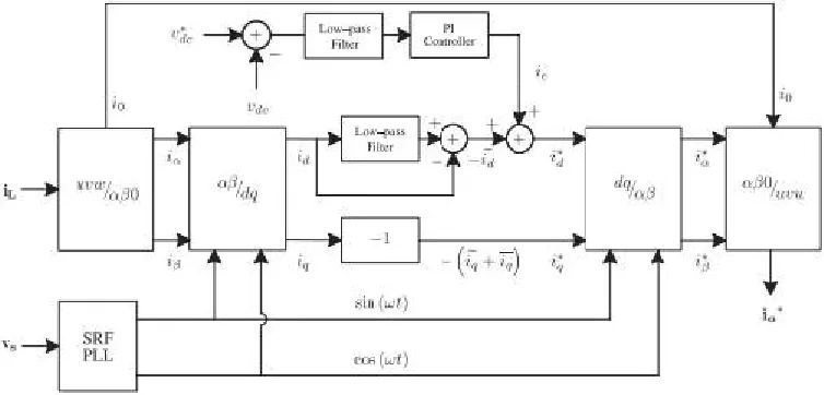
Dq-based current reference generator scheme is used to obtain the active power filter current reference signals. This scheme presents a fast and accurate signal tracking capability. This characteristic avoids voltage fluctuations that deteriorate the current reference signal affecting compensation performance [28]. The current reference signals are obtained from the corresponding load currents as shown in Fig. 5. This module calculates the reference signal currents required by the converter to compensate reactive power, current harmonic and current imbalance. The displacement
power factor (sin φ(L)) and the maximum total harmonic distortion of the load (THD(L)) defines the relationships
between the apparent power required by the active power filter, with respect to the load, as shown
SAPF
SL ==
sin φ(L) + THD(L) 2
sin φ(L) + THD(L) 2
Where the value of THD (L) includes the maximum compensable harmonic current, defined as double the sampling frequency fs. The frequency of the maximum current harmonic component that can be compensated is equal to one half of the converter switching frequency.
Fig 1.5 dq-based current reference generator block diagram.
One of the major advantages of the dq-based current reference generator scheme is that it allows the implementation of a linear controller in the dc-voltage control loop. However, one important disadvantage of the dq-based current reference frame algorithm used to generate the current reference is that a secondorder harmonic component is generated in id and iq under unbalanced operating conditions. The amplitude of this harmonic depends on the percent of unbalanced load current (expressed as the relationship between the negative sequence current iL,2 and the positive sequence current iL,1 ). The second-order harmonic cannot be removed from id and iq , and therefore generates a third harmonic in the reference current when it is converted back to abc frame [31]. Fig. 6 shows the percent of system current imbalance and the percent of third harmonic system current, in function of the percent of load current imbalance. Since the load current does not have a third harmonic, the one generated by the active power filter flows to the power system.
electrolytic capacitor does not affect the current transient response. For this reason, the PI controller represents a simple and effective alternative for the dc-voltage control. √ The dc-voltage remains constant (with a minimum value of 6 vs(rms)) until the active power absorbed by the converter decreases to a level where it is unable to compensate for its losses. The active power absorbed by the converter is controlled by adjusting the amplitude of the active power reference signal ie , which is in phase with each phase voltage. In the block diagram shown in Fig. 5, the dc-voltage vdc is measured and then compared with a constant reference value v∗dc . The error (e) is processed by a PI controller, with two gains, Kp and Ti. Both gains are calculated according to the dynamic response requirement. Fig. 7 shows that the output of the PI controller is fed to the dc-voltage transfer function Gs , which is represented by a first-order system .
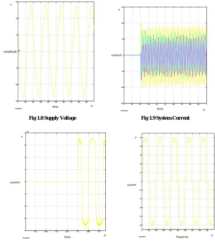
VII.SIMULATION DIAGRAM OF PROPOSED &RESULTS
Fig 1.8 Supply Voltage Fig 1.9 System Current
VII. CONCLUSION
Improved dynamic current harmonics and a reactive power compensation scheme for power distribution systems with generation from renewable sources has been proposed to improve the current quality of the distribution system. Advantages of the proposed scheme are related to its simplicity, modelling, and implementation. The use of a predictive control algorithm for the converter current loop proved to be an effective solution for active power filter applications, improving current tracking capability, and transient response. Simulated results have proved that the proposed predictive control algorithm is a good alternative to classical linear control methods. And the Solar System is also the best means of inverter The predictive current control algorithm is a stable and robust solution. Simulated and experimental results have shown the compensation effectiveness of the proposed active power filter.
REFERENCES
[1] J. Rocabert, A. Luna, F. Blaabjerg, and P. Rodriguez, “Control of power converters in AC microgrids,” IEEE Trans. Power Electron., vol. 27, no. 11, pp. 4734–4749, Nov. 2012.
[2] M. Aredes, J. Hafner, and K. Heumann, “Three-phase four-wire shunt active filter control strategies,” IEEE Trans. Power Electron., vol. 12, no. 2, pp. 311–318, Mar. 1997.
[3] S. Naidu and D. Fernandes, “Dynamic voltage restorer based on a fourleg voltage source converter,” Gener.Transm.Distrib., IET, vol. 3, no. 5, pp. 437–447, May 2009.
[4] N. Prabhakar and M. Mishra, “Dynamic hysteresis current control to minimize switching for three-phase four-leg VSI topology to compensate nonlinear load,” IEEE Trans. Power Electron., vol. 25, no. 8, pp. 1935– 1942, Aug. 2010.
[5] V. Khadkikar, A. Chandra, and B. Singh, “Digital signal processor implementation and performance evaluation of split capacitor, four-leg and three h-bridge-based three-phase four-wire shunt active filters,” Power Electron., IET, vol. 4, no. 4, pp. 463–470, Apr. 2011.
[6] F. Wang, J. Duarte, and M. Hendrix, “Grid-interfacing converter systems with enhanced voltage quality for microgrid application;concept and implementation,” IEEE Trans. Power Electron., vol. 26, no. 12, pp. 3501– 3513, Dec. 2011.
[7] X. Wei, “Study on digital pi control of current loop in active power filter,” in Proc. 2010 Int. Conf. Electr. Control Eng., Jun. 2010, pp. 4287– 4290.
[8] R. de Araujo Ribeiro, C. de Azevedo, and R. de Sousa, “A robust adaptive control strategy of active power filters for power-factor correction, harmonic compensation, and balancing of nonlinear loads,” IEEE Trans. Power Electron., vol. 27, no. 2, pp. 718–730, Feb. 2012.
[9] J. Rodriguez, J. Pontt, C. Silva, P. Correa, P. Lezana, P. Cortes, and U. Ammann, “Predictive current control of a voltage source inverter,” IEEE Trans. Ind. Electron., vol. 54, no. 1, pp. 495–503, Feb. 2007.
[10] P. Cortes, G. Ortiz, J. Yuz, J. Rodriguez, S. Vazquez, and L. Franquelo, “Model predictive control of an inverter with output LC filter for UPS applications,” IEEE Trans. Ind. Electron., vol. 56, no. 6, pp. 1875–1883, Jun. 2009.
[11] R. Vargas, P. Cortes, U. Ammann, J. Rodriguez, and J. Pontt, “Predictive control of a three-phase neutral-point-clamped inverter,” IEEE Trans. Ind. Electron., vol. 54, no. 5, pp. 2697–2705, Oct. 2007.
[12] P. Cortes, A. Wilson, S. Kouro, J. Rodriguez, and H. Abu-Rub, “Model predictive control of multilevel cascaded H-bridge inverters,” IEEE Trans. Ind. Electron., vol. 57, no. 8, pp. 2691–2699, Aug. 2010.
[13] P. Lezana, R. Aguilera, and D. Quevedo, “Model predictive control of an asymmetric flying capacitor converter,” IEEE Trans. Ind. Electron., vol. 56, no. 6, pp. 1839–1846, Jun. 2009.
[14] P. Correa, J. Rodriguez, I. Lizama, and D. Andler, “A predictive control scheme for current-source rectifiers,” IEEE Trans. Ind. Electron., vol. 56, no. 5, pp. 1813–1815, May 2009.
[15] M. Rivera, J. Rodriguez, B. Wu, J. Espinoza, and C. Rojas, “Current control for an indirect matrix converter with filter resonance mitigation,” IEEE Trans. Ind. Electron., vol. 59, no. 1, pp. 71–79, Jan. 2012.
[16] P. Correa, M. Pacas, and J. Rodriguez, “Predictive torque control for inverter-fed induction machines,” IEEE Trans. Ind. Electron., vol. 54, no. 2, pp. 1073–1079, Apr. 2007.
[17] M. Odavic, V. Biagini, P. Zanchetta, M. Sumner, and M. Degano, “Onesample-period-ahead predictive current control for high-performance active shunt power filters,” Power Electronics, IET, vol. 4, no. 4, pp. 414–423, Apr. 2011.
[18] IEEE Recommended Practice for Electric Power Distribution for Industrial Plants, IEEE Standard 141-1993, 1994
[19] R. de Araujo Ribeiro, C. de Azevedo, and R. de Sousa, “A robust adaptive control strategy of active power filters for power-factor correction, harmonic compensation, and balancing of nonlinear loads,” IEEE Trans. Power Electron., vol. 27, no. 2, pp. 718–730, Feb. 2012.
BIOGRAPHY
CH.Pardhasaradhi received the M.Tech degree from the Jntu Kakinada University (2009), India, and having the teaching experience since 2002 the electrical engineering. Present Working as a Assoc.Proff and Head of the department (EEE) in St.Mary's Group of institutions Guntur. And also a Phd Scholor From Acharya nagarjuna UniversityGuntur. His current research interests include Power Systems & FACTS Protecting devises and also several algorithms particularly in electronics and electrical applications.
D.Thirupathi Rao received the b tech degree from the JNTU Kakinada university in 2014.and he had participated in more than 14 national level seminars and 3electrical conferences and also published 6more Electrical research articles in International JOURNALS .Particularly he shows his interest in the field ofPower electronics & Renewable energy Resources Present he working on Hybrid Electrical Vehicles in association with Joseph Sreeharsha & Mary Indraja Educational SocietyHyderabad.