Novel Modeling and Dynamic Simulation of
Spin Valve Sensor for the Next Generation
Vehicles
Ajin A. S.1, Arya P. M.2, Karthika C.3, Athulya H.4
Assistant Professor, Department of Electronics & Communication Engineering, Ahalia School of Engineering &
Technology, Palakkad, Kerala, India1
B. Tech. Student, Department of Electronics & Communication Engineering, Ahalia School of Engineering &
Technology, Palakkad, Kerala, India2,3,4
ABSTRACT: In the present scenario, vehicle population is increasing day by day which will lead to accidents. There are various vehicle safety technologies that are developed in the automotive industry to ensure the safety and security of automobiles and passengers. Notable examples include ABS, ABS with EBD, Airbag etc. All these systems are controlled mainly by Hall Effect sensors. Because of the fault in sensor, most of the times these systems fail to respond in a real time world. This will led to threat in passenger safety. Thus we need to identify a smart sensor to solve this issue. The proposed sensor will be based on spintronics, where we get the output signal as direct square waves with fast response. Hence the decision making is very simple without delay. In short, the idea is to incorporate high speed electronics with mechanical systems to get a better response.
KEYWORDS: Spintronic Sensors, Automobile Sensors, Speed sensor, Passenger safety
I. INTRODUCTION
Vehicles have become faster and smarter in the last decade. The increasing complexity of the traffic situation on our roads is placing high demands on car drivers. Modern vehicles have come with the adoption of advanced safety features like ABS, Airbag, and brake assist. Driver assistance systems relieve the burden on the driver and optimize road safety. Thus the proper working of sensors used in these systems play an important role in providing safety to passengers. In fact more than how quickly your car accelerates, it’s more important how quickly it decelerates. Being able to slow down or stop at a moment’s notice will help to avoid an accident or incident. Improperly working brakes will not do the job they are designed to do and will not be as effective when needed, especially in a panic stop situation. The components of an ideal break system includes brake pedal, master cylinder, break shoe and bleed valve. All of these components need to be in good shape and working properly for the vehicle to have 100% brake system effectiveness while driving. Sometimes due to the contamination in the brake fluid can decrease the effectiveness of the hydraulics within the brake system causing a delay or reduction in braking power. So to overcome the ill effects of brake system, various driver assistance systems such as ABS, EBD etc. came into existence. In the proposed idea the existing Hall Effect sensors are replaced by spin valve sensors which come under Spintronics. Thus by introducing thespin valve sensors in these advanced safety technologies, performance of the system can be enhanced. As a result passenger safety can be ensured.
alignment of the magnetization in the layers. So by introducing the spin valve sensors in this advanced safety technologies, the response time can be decreased and thus fast output is obtained.
II. PROPOSEDSYSTEM
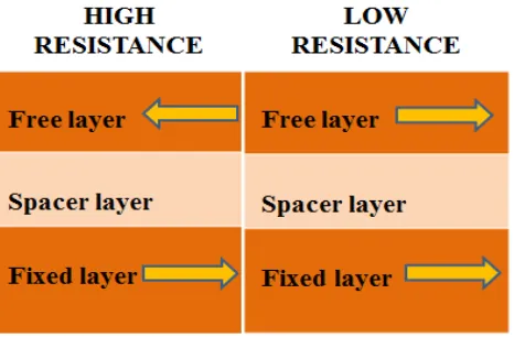
A spin valve is a device, consisting of two or more conducting magnetic materials. The electrical resistance can change between two values depending on the relative alignment of the magnetization in the layers. The resistance change is a result of the GMR(Giant Magnneto Resistance) effect.. In the spin valve structure the magnetic layers of the device align up or down depending on an external magnetic field.
Fig 1: Layered structure of spin valve
A spin valve consist of a non-magnetic material sandwiched between, two ferromagnets. The bottom layer is fixed or pinned by an antiferromagnet which acts to raise the magnetic coercivity.This layer which act as a “hard” layer. The upper layer is free or unpinned. It behaves as a “soft” layer. Due to the difference in coercivity, the soft layer changes polarity at lower applied magnetic field strength than the hard one. Depending on the applied magnetic field strength, the soft layer switches polarity, producing two distinct states. A parallel direction indicates a low-resistance state, and an antiparallel indicates a high-resistance state. Spin valves work because of a quantum property of electrons called spin. Due to a split in the density of state of electrons in the ferromagnets, there is a net spin polarization. An electric current passing through a Ferro magnet therefore carries both charge and a spin component. However, by passing a current from a ferromagnet into a normal metal it is possible for spin to be transferred. A normal metal can thus transfer spin between separate Ferro magnets, subject to a long enough spin diffusion length. Spin transmission depends on the alignment of magnetic moments in the Ferro magnets. In the spin valve sensor an antiferromagnetic layer is required to pin one of the ferromagnetic layers. This results from a large negative exchange coupling energy between Ferro magnets and antiferromagnets in contact. The non-magnetic layer is required decouple the two ferromagnetic layers so that at least one of them remains free.Sensors utilizing Giant Magneto-Resistance are expected to have a greater sensitivity and larger signal than the AMR(Anisotropic Magneto Resistance) sensor.To explore the feasibility of spin valve sensor, unshielded devices are fabricated.
III.METHADOLOGY
Structure of the Spin Valve Sensor
arranged one over the other. Ellipsoid shape is preferred because magnetization is higher along the longer axis of the ellipsoid shape. All of these are done using COMSOL software. COMSOL Multiphysics is engineering simulation software to create accurate models.Several modules are available for COMSOL, categorized according to the applications areas, namely Electrical, Mechanical, Fluid, Chemical, Multipurpose, and Interfacing. Multipurpose and interfacing are one of the greatest advantage of this software.
Material Composition of the Layers
The material composition for each layer is finalised after its magnetic field is studied. Each layer is allotted with different materials. There are four layers fixed, free, pinned and pinning. The top layer is a free layer, middle is the spacer layer, and the bottom is the fixed layer. The pinned and pinning layer forms the fixed layer. Since the top layer is the free layer the material allotted for this layer is soft magnetic materials. The spacer layer which act as an insulator, hence it is made up of diamagnetic material. The bottom layer is made up of hard magnetic materials. The material composition for the top layer is taken as NiFe. Copper is used for spacer layer. Pinned layer is made up of Cobalt and pinning layer is made up of FeMn. The switching speed of the sensor is determined by its material composition. Material is selected based on the number of magnetic domains it possess.
Field Study
Sensitivity of the sensor is determined using its field study. The field study during parallel and anti-parallel conditions were studied using oommf software. The magnetic fields during both the switching conditions are studied. Magnetic fields are absent during anti-parallel conditions. Maximum fields are present during parallel conditions. The magnetic field relation with various frequency range are also studied.
Performance Characteristics of Sensor
The performance characteristics of the sensor are analysed using OOMMF software. OOMMF stands for Object Oriented Micro Magnetic Framework. It has been the most widely used open source micro magnetic modelling and simulation suite.OOMMF is written in C++, a widely-available, object-oriented language that can produce programs with good performance as well as extensibility. For portable user interfaces, we make use of Tcl/Tk so that OOMMF operates across a wide range of Unix, Windows, and MacOSX platforms. The important quality of a sensor is its performance characteristics. A good sensor will respond to its performance parameters quickly. As a result of this we studied the performance characteristics such as response time and sensitivity. In order to analyze the performance of the sensor, studied the magnetic spins during parallel and anti-parallel conditions.
IV.EXPERIMENTALRESULTS
a) Geometric Pattern
Fig 2: Square shape and its characterization
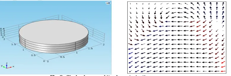
The figure above shows the structure of the spin valve sensor designed using square shape and its characterization. The stability of the sensor mainly depends on its structure. So it is important to choose the structure having high stability. This structure is made by sandwiching four square layers in the z direction. When the structure is in square shape it forms more magnetic domains. These domains requires more time for rotation. Hence the switching speed of the sensor increases. Thus this shape is not preferred for the spin valve structure.
Fig 3: Circle shape and its characterization
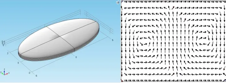
Fig 4: Ellipsoid shape and its characterization
The above figure shows the structure of spin valve sensor using ellipsoid shape and its characterization. The greatest advantage of this shape is that it has only two magnetic domains. The output state of the spin valve sensor contains two states. Thus by the formation of two magnetic domains it is easy to switch one state to another. Therefore its switching speed increases. As a result it easily reaches the magnetic saturation value. In the ellipsoid the magnetic saturation is oriented towards the long axis. There by the output is more stable. Due to these advantages ellipsoid shape is preferred for the spin valve sensor structure.
b) Material Composition
The switching characteristic of the spin valve sensor is studied by analyzing its material composition. The response time of the sensor is the time it requires to switch from one state to another i.e. either from low resistance to high resistance or vice versa. The switching time will be in nanoseconds range. The switching from one state to another is determined by varying its input frequency. The presence and absence of magnetic field is represented by the frequency. The presence of magnetic field is denoted by parallel state and absence by anti-parallel state. The switching speed is determined using oommf software. How quickly it switches one state to another and reaches its original state, the response time will be high. Based on the various materials the response time will vary.
Fig 5: Parallel condition Fig 6: Anti-Parallel condition
spins can always form loops. So based on choosing the correct geometry the formation of loops can be avoided. By choosing the ellipsoid there is less possibility of forming loops. Hence the response of the sensor is more accurate.
c) Graphs on induced field and demagnetization energy
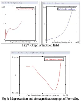
The below graph shows the exchange energy of various materials. The graph is plotted against exchange energy verses simulation time. X axis represents simulation time and in Y axis represents exchange energy. The first graph shows the field sensing capability of a material. From the graph, it is clear that the sensing is low. The second graph indicates the Permalloy material. It shows a constant increase in the exchange energy with time. Since the induced field is high it can achieve more switching. This indicates high field sensing capability that is it is quickly magnetized.
Fig 7: Graph of induced field
Fig 8: Magnetization and demagnetization graph of Permalloy
The above graph shows the demagnetization curve of Permalloy material. The X axis is simulation time and the Y axis is demagnetization energy. It shows the magnetization and demagnetization of Permalloy material. From the graph Initially it is in parallel state then it switches to anti-parallel state.
V. CONCLUSION
getting output and less sensitivity. To overcome these limitations a new vehicle speed sensor is proposed for the efficient braking system. The proposed spin valve sensor is a high speed switch which can perform more accurately and quickly than Hall Effect sensor. This sensor is used in brake assistance technologies such as Anti-lock braking system, ABS with EBD, BA and Airbag.
Here the spin valve sensor is designed using comsol software and its switching characteristics are studied by oommf software. The feature of the proposed sensor includes response time, Stability, accuracy. In order to gain high stability the shape of the spin valve sensor is concluded as ellipsoid. The sensitivity is found by placing a magnetic layer near the sensor. Material compositions of the layers decide the switching speed of the sensor. It is determined from OOMMF software. From these observations it is concluded that Permalloy provides fast switching speed. Thus the response of spin valve sensor is more accurate than Hall Effect sensor. This proposal prevents accidents in future and there by enhance the passenger safety.
Future perspective of spin valve sensor and its design techniques and performance will be dramatically influenced by progresses in different fields of research. Advancement in bio Nano technology, computer science, molecular diagnostics, with increasing demands for miniaturized medical devices. These devices need highly sensitive, fast, reliable, cost effective, easy to use spin valve sensors. Which can meet future medical devices needs is a challenging process.
REFERENCES
[1] Kris Frohman, Marvin Sandner,"A novel magneto resistive wheel speed sensor with low temperature drift and high stray field immunity". IEEE.transaction on instrumentation and Measurement Society” 2018.
[2] Kris Rohrmann, Marvin Sandner"A readout concept for AC-driven xMR sensors in automotive wheel speed applications".An IEEE transaction
on strategy analytics,dez16th.2018.
[3] Aymanen Yan ID ,Weigong Zhang "Wheel Force Sensor-Based Techniques for Wear Detection and Analysis of a Special Road".2018.
[4] Divyata Khachane1, Prof. Anjali Shrivastav2."Antilock Braking System and Its Advancement". Volume: 03 Issue: 05 | May-2016.
[5] Lisa Jogschies, Daniel Klaas, ."Recent Developments of Magneto resistive Sensors for Industrial Applications. "Volume no.15.2011.
[6] H.-L. Ross, Functional Safety for Road Vehicles: New Challenges and Solutions for E-mobility and Automated Driving, Springer, 2016.
[7] M. Prochaska, “Green driving – technologies for sustainable mobility,” Proceedings of the 15th IEEE International Symposium on Theoretical
Electrical Engineering (ISTET), Lübeck, Germany, June, 22.-24., 2009.
[8] S. Tumanski, Thin Film Magneto resistive Sensors, IoP Publishing, 2001.
[9] K. Kuijk, W. van Gestel and F. Gorter, “The barber pole, a linear magneto resistive head,” IEEE Trans. On Mag., Vol. 11, No. 5, Sep. 1975,
pp. 1215-1218.
[10] P. Ripka, M. Tondra, J. Stokes and R. Beech, “AC-driven AMR and GMR magneto resistors,” Sensors and Actuators A, Vol 76, No.1,