TOC
FCC Information... 12
About This Manual... 13
Related Documents: ... 13
2
System Configuration ...15
System Hardware ... 16
KSU ... 16
System Peripheral Connections ... 17
Configuration Options ... 18
Main System KSU ... 19
Expansion Module 3 x 8... 20
Option Module ... 21
Voice Processing System ... 22
3
System Specifications ...23
Specifications ... 23
Power Requirements ... 23
Dimensions... 23
Mounting ... 23
4
Installation ...27
Installation ... 27
Basic Tools and Supplies ... 27
Product safety and safety guidelines... 27
Installation Planning ... 28
Module Installation... 29
Wiring and Connectors ... 32
Connecting Extensions... 34
Station Message Detail Recording (SMDR) ... 35
Initialization Procedure ... 37
5
Telephone Operation ...39
TOC
Accessing Specific CO Lines ...44
Account Code ...44
Answering Machine Emulation ...44
Attendant ...45
Attendant Administration (Admin.) ...46
Authority Code (Traveling Class of Service)...48
Automatic Hold ...48
Automatic Record ...49
Automatic Selection (CO/Intercom) ...50
Auxiliary Lamp LED Status Bar...51
Background Music (BGM) ...52
Barge-In (Intrusion) ...52
Busy Lamp Field (BLF) / Direct Station Select (DSS) ...52
Busy Ring Allow/Deny...53
Call Attendant (Operator)...54
Call Back – Extension ...54
Call Duration Timer (Incoming/Outgoing) ...55
Call Forward Extension ...56
Call Park / Call Park Answer ...57
Call Pickup Group...58
Caller ID (Standard on all CO Lines) ...59
Caller Identification - Call Log...59
Call Waiting...60
Camp On – CO Line...60
Conference...61
Data Rate...62
Day and Night Modes...62
Default Flexible Buttons...63
Default Settings ...63
Directed Call Pickup ...64
Distinctive Ring ...64
Do Not Disturb ...64
Do Not Disturb - Override ...65
Enhanced Lettering Scheme ...66
Extension Feature Status Check ...67
Extension Groups ...68
Extension Password / Phone Lock ...68
Extension Pick Up Groups ...69
Extension Programming Copy ...69
TOC
External Paging ... 72
FAX Detection with Automatic Transfer ... 73
Feature Key Allow ... 73
Flash Recognition – Analog Port SLT ... 75
Flash – CO Line... 76
Flash - PBX Line... 76
Flexible Feature Button Programming... 77
Forced Intercom Tone Ring... 78
Group Call Pickup ... 79
Headset Jack ... 79
Hold, System (Common) & I – Hold Indication ... 79
“Hold” Remind Time ... 80
Holding Call Answer – Select ... 80
Hot Key Enable / Disable ... 81
Hour Mode Selection 12/24 ... 82
Hunt Groups... 82
Intercom Calling - Non Blocking - Intercom Button... 84
Intercom Call Back ... 85
Intrusion - Extension... 85
Intrusion Tone ... 86
Last Number Redial ... 87
Least Cost Routing... 88
Loud Bell... 88
Messaging – Premises... 89
Message Waiting ... 90
Modem (“Extension 55”)... 90
Monitor - Extension ... 91
Music-on-Hold ... 92
Mute ... 92
Off Hook Voice Announce ... 93
On Hook Dialing (Hot Key Pad) ... 93
One Touch Transfer... 94
Page ... 94
Page (Allow / Deny)... 95
Page (Meet Me) ... 95
Pause / Pause Insertion ... 96
Phone Lock / Unlock... 96
Privacy ... 97
Private To... 98
TOC
Relay Control ...101
Save Dialed Number (SDN) ...102
Single Line Telephone - Flash ...102
Single Line Telephone - CO Line Flash ...103
Speakerphone ...104
Security Control ...104
Speed Dial (ABBR) – Extension /System...105
Status Message ...106
System Reminder ...107
Text Messages...108
Touch Tone On/Off ...109
Transfer ...109
Transfer Beep ...110
Voice Announce / Hands-free Reply ...111
Voice Call Recorder (One Touch Record) ...112
Voice Processing Digital (Integration)...113
Volume Control...114
Warning Tone / CO Line Call Limiter ...115
6.0
Database Programming... 117
Database Administration ... 117
Programming Mode ...119
6.1
Extension Programming ... 121
Day Class ...122
Night Class ...122
Monitor COS ...122
Line Assignment ...123
Receive Assignment ...123
Ring Assignment ...124
Extension Group...124
Warning Tone...124
Outgoing Drop ...125
Incoming Drop ...125
Location...126
Extension Position...126
TOC
CFW Auxi Lamp... 128
Default Settings... 128
Do Not Disturb (DND) Function Allow... 128
BEEP 2 Allow ... 129
Pre-CFW ... 129
ECF Allow... 130
Forced LCR... 130
6.2
CO Line ...131
Day Class ... 131
Night Class... 132
Hunt Group Answer ... 132
Dialing [Type]... 132
Line Type... 133
Loud Bell... 133
Line Group (CO Line Groups)... 134
Private To... 134
Distinct Tone (Distinctive Ring)... 134
Fax XFR To ... 135
Gain (RX) ... 135
Gain (TX) ... 135
DTMF Disable ... 136
CID Mode ... 136
Pre-CFW ... 136
Privacy Rls ... 137
6.3
Call Handling...139
Intrusion... 139
Intrusion Tone ... 139
Exclusive Hold Time ... 140
PBX Flash ... 140
CO Flash... 140
Remind Time ... 141
Pause Time ... 141
PBX Code... 141
TOC
Alternate Ring Time...144
Tone Sender ...145
Single Line Telephone –Hook-Switch Flash...145
Operator Code...146
SMDR Time ...146
SMDR Output ...146
Hunt Method...147
BB Call Pause ...147
VM MON TIME...148
Voice Mail Reserve Port ...148
DTMF Tone ...148
Wait CID_T (CID Feature) ...149
International Prefix (CID Feature) ...149
Country Code (CID Feature) ...149
Long Distance Prefix (CID Feature)...150
Local Area Code(s) (CID Feature) ...150
SYS External Call Forward ...151
LCR Time...152
6.4
Resource ... 153
Ring Scheme ...153
Letter Type...153
Attendant ...154
Alternate ...155
Modem Number ...155
System Reminder ...155
Time Switching ...156
DB Password ...157
User Password ...157
User Name...158
Preprogrammed Message...159
System ABBR No ...161
Line Copy ...162
Extension Copy...163
System Time ...164
RMT X_RATE ...165
SMDR X_RATE ...165
Hour Mode ...165
TOC
Feature Key Copy ... 167
UART Type ... 168
CID Repeater Modulation ... 168
Volume Limit ... 168
Service Mode... 169
Option Port Function—SLT/Door Phone ... 170
Option Sensor Function—Door Lock/Secure ... 171
Security Alarm Action ... 172
Option Relay Function—Door Open / Monitor / Secure mode ... 174
Incoming Filter ... 174
6.5
Restriction ...177
Call Restriction... 177
Line Call Discrimination ... 177
Password Dial Table (Traveling COS) ... 179
Least Cost Routing... 181
6.6
Control...187
Control... 187
Data Auto Answer ... 187
Extension Hunt Group ... 188
Voice Mail ... 190
Control Contact (Dry Contact) ... 191
Location to Directory... 192
Directory to Location... 194
System Warm Start ... 195
System Cold Start ... 195
A
Appendix A...197
Extension 55 ... 197
Remote Programming Connect... 197
Remote Programming Disconnect ... 199
TOC
Shutdown Procedure ...203
voice processing Call Flow ...204
Administrative Programming ...205
Voice Processing Programming Menu ...205
Main Menu Programming Flow...206
1 General Settings ...207
3 = System Time ...209
4 Holiday Schedule...210
5= System Interface Codes ...210
6 = Operator Operations ...210
7 = Extension Programming ...211
8= Department Programming ...212
9 = Mailbox Settings ...214
2 Advanced Settings ...215
1 Language...215
2 Out Calling...216
3 Call Record Reminder Tone ...216
4 Storage Length ...216
5 Incorrect Input...216
6 LAN Port ...216
7 Broadcast Groups...216
Programming Using TCP/IP...217
TCP/IP Login ...218
Main Programming Menu ...218
Extension ...221
DSP...222
Department...223
Version ...224
Notices
The Contents of this manual are subject to change without notice and do not constitute a commitment on the part of XBLUE Networks, LLC., Every effort has been made to ensure the accuracy of this document, however, due to ongoing product improvements and revi-sions, XBLUE Networks, LLC., cannot guarantee the accuracy of printed material after the date of publication nor can it accept the responsibility for errors or omissions. This docu-ment will be updated and revise as needed.
Reproduction, publication, or duplication of this manual, or any part thereof, in any man-ner, mechanically, electronically, or photographically, is strictly prohibited. © Copyright 2006 by XBLUE Network, LLC. All rights reserved.
Warning: This service information is designed for experienced repair technicians only and
is not designed for use by the general public. It does not contain warnings or cautions to advise non-technical individuals of potential dangers in attempting to service a product. Products powered by electricity should be serviced or repaired only by experienced profes-sional technicians. Any attempt to service or repair the product or
products dealt with in this service information by anyone else could result in serious injury or death.
1
FCC
Inf
ormation
This equipment generates, uses, and can radiate radio frequency energy, and if not installed and used properly, that is, in strict accordance with the instruction manual, may cause interference to radio and television reception. This equipment has been tested and found to comply with the limits for a Class A computing device in Subject J of Part 15 of FCC Rules, which are designed to provide reasonable protection against such interference. However, there is no guarantee that interference will not occur in a particular installation.
If this equipment does cause interference by one or more of the following measures: 1. Reorient the receiving antenna,
2. Relocate the key service unit and key telephones with respect to the receiver, 3. Move the equipment from the receiver,
4. Plug the key service unit into a different outlet so that the equipment and receiver are on different branch circuits.
FCC
Information
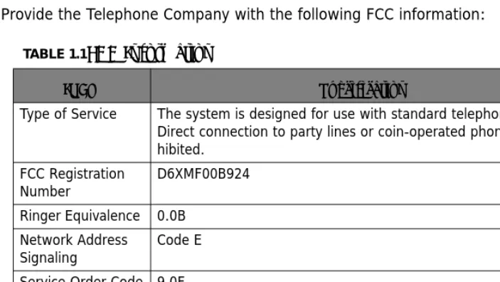
Provide the Telephone Company with the following FCC information:
TABLE 1.1FCC Information
ITEM Specification
Type of Service The system is designed for use with standard telephone lines. Direct connection to party lines or coin-operated phones is pro-hibited.
FCC Registration
Number D6XMF00B924
Ringer Equivalence 0.0B Network Address Signaling
Code E
Service Order Code 9.0F Facility Interface
Code 02LS2
Required Network
Re
la
te
d D
oc
um
en
ts
:
1
About
This
Manual
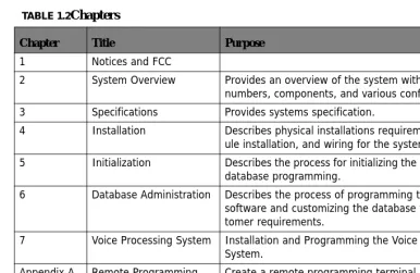
This manual provides installation instructions for the System. The following table summa-rizes the sections in this manual:
Related
Documents:
Extension User Guide (Full)
Quick Reference Card TABLE 1.2Chapters
Chapter Title Purpose 1 Notices and FCC
2 System Overview Provides an overview of the system with the model numbers, components, and various configuration 3 Specifications Provides systems specification.
4 Installation Describes physical installations requirements, mod-ule installation, and wiring for the system.
5 Initialization Describes the process for initializing the software for database programming.
6 Database Administration Describes the process of programming the system software and customizing the database to meet cus-tomer requirements.
7 Voice Processing System Installation and Programming the Voice Processing System.
Appendix A Remote Programming
Modem Create a remote programming terminal by “joining” two system together. Appendix B Menu Bypass Codes Listing of all the programming codes, sorted by
1
Re
la
te
d D
oc
um
en
ts
This Hybrid Telephone System has a modular single shelf flat-pack design, which comes configured with 3 Central Office lines by 8 Digital Extensions and 2 analog extensions and can expand to a 9 Central Office lines by 24 Digital Extensions and 4 analog extension ports. In addition, The system comes equipped to receive Caller ID from the telephone company, if it is supplied, and any analog telephone with Caller ID capability will also receive Caller ID.
Additional components include an Option module which provides 2 analog ports, BGM, Relays (four), Security Sensors (four), External Paging Port, Loud Bell Contact and one RS232c for SMDR/Remote Programming Software, as well as an integrated Door Phone and an 8 Port Flash Voice Processing System (VPS).
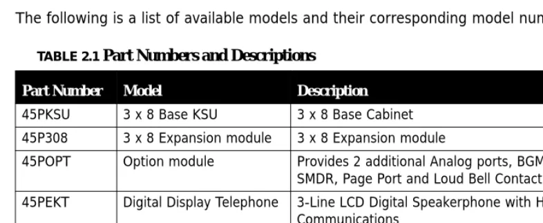
The following is a list of available models and their corresponding model numbers:
TABLE 2.1 Part Numbers and Descriptions
Part Number Model Description
45PKSU 3 x 8 Base KSU 3 x 8 Base Cabinet 45P308 3 x 8 Expansion module 3 x 8 Expansion module
45POPT Option module Provides 2 additional Analog ports, BGM, Relays, SMDR, Page Port and Loud Bell Contact
45PEKT Digital Display Telephone 3-Line LCD Digital Speakerphone with Handsfree Communications
45PDRP Door Phone Integrated Door Phone with Handsfree Response
KSU
2
System
Hardware
KSU
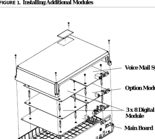
An external power supply provides power for this stylish compact cabinet and the main board which is equipped to operate 3 Central Office Lines, 8 Digital Extensions, and 2 Ana-log ports. The additional 3 x 8, option module, and voice mail modules connects to the main board using a special “Mate Lock” connector and flat ribbon cables. Once powered up, the system will automatically identify each additional module that is installed.
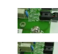
Figure 1. shows how the additional modules are installed.
FIGURE 1.Installing Additional Modules
3 x 8 Digital Expansion Module
Voice Mail System
Option Module
Sy
stem P
eripher
al
Connections
2
System
Peripheral
Connections
The system is equipped with many of the necessary peripheral connections required to operate other resources in conjunction with the system.
Ethernet Connection
Voice Mail Serial Port
SMDR Port
MOH & BGM Power
External Power
Page
Switch
Input Ram Clear
Initialization
Configur
ation Options
2
Configuration
Options
At default, the system comes equipped with 3 Central Office Lines, 8 Digital Extensions and 2 Analog Extensions, but because of the modular design the system can be equipped with affordable modules to increase the system size to a maximum of 9 Central Office Lines, 24 Digital Extensions and 4 Analog Extensions. In addition, an 8 port integrated Voice Mail System can also be added.
The following table describes the building block structure of the system:
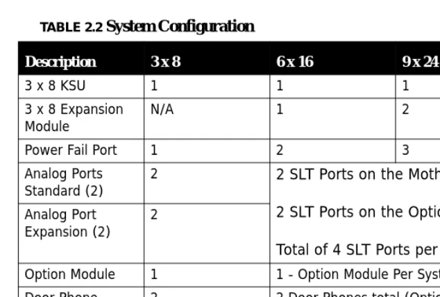
TABLE 2.2 System Configuration
Description 3 x 8 6 x 16 9 x 24
3 x 8 KSU 1 1 1
3 x 8 Expansion
Module N/A 1 2
Power Fail Port 1 2 3
Analog Ports Standard (2)
2 2 SLT Ports on the Motherboard
2 SLT Ports on the Option Module
Total of 4 SLT Ports per System Analog Port
Expansion (2) 2
Option Module 1 1 - Option Module Per System Door Phone 2 2 Door Phones total (Option Module)
Replaces 2 SLT Ports Integrated Voice
Main S
ystem
KSU
2
Main
System
KSU
The basic system comes with a power supply, and a motherboard configured as a 3 x 8. The Motherboard has an integrated Main Distribution Frame (MDF), designed to eliminate costly ancillary products, such as M66 split blocks, and is used like a patch panel.
•
Common control circuit with 80188 CPU•
Memory span: 1Meg ROM, 512KB RAM•
3 analog CO line ports plus 1 Power Failure port on port-1•
Dual mode caller ID detection (FSK and DTMF)•
8 digital extension ports•
2 analog extension ports•
Caller ID (Type 1, FSK)•
Built-in FSK transceiver for remote programming via EKT•
DSP control for multi-party conference, tone plant and tone detector•
External Music on Hold Connection using a mini-mono plug•
Battery Back Up for RAMExp
ansion
Module 3
x
8
2
Expansion
Module
3
x
8
A 3 x 8 expansion module can be installed in the KSU, growing it from its initial 3 x 8 con-figuration to 6 x 16. Add an additional 3 x 8 expansion Module brings the system up to its maximum capacity of 9 x 24.
Like the main board, each 3 x 8 expansion Module comes with an integrated Patch Panel - MDF, making installation and Moves, Adds and Changes, quick and easy. Each Module is connected to the main board using a ribbon cable which is inserted into the E308 pin con-nector.
Each 3 x 8 Module comes equipped with 3 Central Office connectors and 8 Digital Exten-sion connectors.
•
3 analog CO line ports plus 1 Power Failure port on port-1•
Dual mode caller ID detection (FSK and DTMF)•
8 digital extension ports3 Central Office Lines
8 Digital Extensions
Option Module
2
Option
Module
The Option Module interfaces with the following ancillary devices:
•
2 Single Line Telephone Ports that double as Door Phones•
External Page Port to connect to an external paging unit (amplifier).•
Loud Bell Contact to connect an external bell or strobe light.•
RS232C (SMDR/RMP) Port to connect an SMDR Serial Printer, or Call Accounting Soft-ware or Remote Programming SoftSoft-ware Application.•
4 – Door Relays which supply a momentary contact closure, which can be used to release an exlectronic door lock interface. Connects using a screw terminal interface.•
4 – Door Sensors which are used to detect an opening of a device wth a contact closureon it, such as an open door.
The single line device ports do double duty and become door phones which can be pro-grammed to integrate with a door opening relay and/or a door open sensors. A ribbon cable connects the expansion Module to the motherboard and is inserted into the Option board pin connector.
•
Over-voltage Protection per CO Circuit•
Polarity Guard per CO CircuitSLT/Door Phone
External Page Port
Vo
ice Pr
ocessing S
ystem
2
Voice
Processing
System
The Integrated Voice Processing System (VPS)can be added to the main cabinet to provide Voice Mail functionality as well as Automated Attendant.
Specifications
Power
Requirements
Dimensions
Mounting
TABLE 3.1 Power
A.C. Power 110 or 220 V AC (Selectable)
Frequency 60 Hz
Power Consumption 100 Watts max
Current Rating (Max) 1 Amp AC, 3 Amp DC
Loud Bell Contact 1 Amp DC (Do not use AC!)
TABLE 3.2 System Dimensions - Measurement in Inches
KSU 12 1/2 L x 9 1/4 W x 3 7/8 H
TABLE 3.3 Mounting Methods
Mounting Methods Wall Mount
Specifications
3
Operating
Environment:
Wiring:
Maximum
System
Configurations:
TABLE 3.4 Environmental Conditions
Temperature 32° to 95° degrees Fahrenheit
Relative Humidity 5 to 90 percent Non-Condensing
TABLE 3.5 Cable Layout
Digital Telephone 2 Wire - Star Type
Single Line Telephone 2 Wire - Star Type
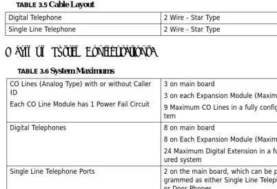
TABLE 3.6 System Maximums
CO Lines (Analog Type) with or without Caller ID
Each CO Line Module has 1 Power Fail Circuit
3 on main board
3 on each Expansion Module (Maximum of 2) 9 Maximum CO Lines in a fully configured sys-tem
Digital Telephones 8 on main board
8 on Each Expansion Module (Maximum of 2) 24 Maximum Digital Extension in a fully config-ured system
Single Line Telephone Ports 2 on the main board, which can be pro-grammed as either Single Line Telephone ports or Door Phones.
2 on the Option Module
4 Maximum SLT Extensions in a fully configured system
Speci
fications
3
CO
Line
Interface
Specifications:
Switching
Technology:
Extension
Interface
Specifications:
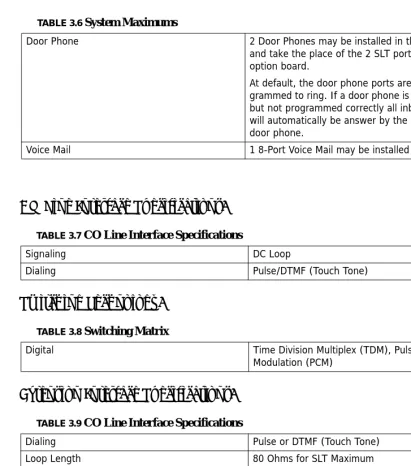
Door Phone 2 Door Phones may be installed in the system
and take the place of the 2 SLT ports on the option board.
At default, the door phone ports are pro-grammed to ring. If a door phone is connected, but not programmed correctly all inbound calls will automatically be answer by the connected door phone.
Voice Mail 1 8-Port Voice Mail may be installed
TABLE 3.7 CO Line Interface Specifications
Signaling DC Loop
Dialing Pulse/DTMF (Touch Tone)
TABLE 3.8 Switching Matrix
Digital Time Division Multiplex (TDM), Pulse Code
Modulation (PCM)
TABLE 3.9 CO Line Interface Specifications
Dialing Pulse or DTMF (Touch Tone)
Loop Length 80 Ohms for SLT Maximum
Ringer 70 V AC, 35 Hz SLT
Specifications
3
Maximum
Cable
Length:
TABLE 3.10 Digital Extension Wiring
26 AWG 650 Ft.
24 AWG 1133 Ft.
22 AWG 1586 ft.
TABLE 3.11 Single Line Telephone Extension Wiring
26 AWG 850 Ft.
24 AWG 1416 Ft.
Installation
Basic
Tools
and
Supplies
Minimum of Category 3 - 3 or 4 twisted pair cable run from the MDF to each telephone terminal device.
4 or 6 conductor modular jack assemblies for all extension terminals.
Uninterrupted Power Supply (UPS) system to protect the system in the even of a voltage spike. Standard telephone hand tools and mounting hardware for the KSU, MDF backboard, terminal blocks, modular jack assemblies, etc.
Product
safety
and
safety
guidelines
1. Never perform any wiring in a wet location or while standing in water. 2. Do not perform telephone wiring during a lightning storm.
3. To maintain the system in good operation, an isolated, dedicated outlet for the system is needed. The outlet should be AC power supply with 120 ~ 240V ± 10% at 50 ~ 60Hz.
4. The install location should be well ventilated, have an optimum temperature range of 40° ~ 95° F and a relative humidity range of 20 ~ 80%.
5. For cooling purposes, ample air space should be provided for the KSU, the KSU should not be exposed to direct sunlight, heat or dust.
6. Do not install the system in a strong magnetic field, such as those generated by heavy motors, television, copy machine or some kitchen appliances.
7. The system should be located in an electrically noise-free environment to avoid interfer-ence.
8. To reduce interference, use independent wiring for extensions connected to this system. 9. Do not include connections for antenna, power supplies and/or internet connections in
In
stallation Planning
4
10.Earth ground for the KSU should less than 3 Ohms.
Note:
The manufacturer warranty does not cover damage caused by power line surges or light-ning damage.
Installation
Planning
1. The system should be located within 5 feet of the isolated dedicated 120 ~ 240V ± 10% at 50 ~ 60Hz, and connected to a UPS. Do not use an extension cord!
2. Locate the Telephone Company demarcation point and extend them to the MDF. 3. The system (MDF) should be mounted on a painted (white or black) 3/4 inch plywood
back board. Be sure that the back board is level and at least 24 inches off the floor. Also, be sure that it is large enough for the system and all of the peripheral equipment.
4. Locate a suitable, known good, earth ground such as a cold water pipe - preferably within 10 feet of the MDF. It is suggested that a cold water pipe, when used as a ground, is traced to its point of origin to ensure that there is no non-metal sections, which may compromise the ground.
Module Installation
4
Module
Installation
3 x 8 Expansion Module
1. Remove the KSU cover.
2. Locate the pin connector socket labeled “308EXP”.
3. Remove the screws from the motherboard, and replace them with the brass-colored stand-off posts supplied with the expansion module.
4. Insert the module, but before securing it, plug the ribbon cable into the pin connector socket labeled “308EXP”.
5. Place the previously removed screws into the top of the stand-offs to secure the mod-ule.
6. Replace the cover, and power the system up.
Option Module
1. Remove the KSU cover
2. Remove the screws from the motherboard, and replace them with the brass-colored stand-off posts supplied with the Option Module.
3. Remove the plastic protective cover from inside the KSU.
4. Insert the Module, and plug the ribbon cable into the pin connector socket labeled “Option Board”.
5. Place the previously removed screws into the top of the stand-offs to secure the Option Module or place the standoffs that are supplied with the Voice Mail system.
6. Replace the cover, and power the system up.
Adding Loud Bell Control
One “dry-contact” RELAY 24VDC/1A is provided on the Option Module for use with external ringing devices. The system can be programmed to activate the dry contact whenever pro-grammed CO Lines ring.
Caution
Module I
nstal
lation
4
Adding an External Page
The External Page Port is designed to recieve an external paging unit (amplifier) to allow voice paging over external speakers. The amplifier interface should be 600 ohms.
Single Line Telephones or Door Phones
Extensions 36 and 37 found on the Option Module can be programmed as either Single Line Telephone devices or Door Phones.
Door Sensor
Four security sensors, with a screw ther-mal interfaces, show when an electronic sensor device circuit is open, sending an alert to the programmed extensions and external telephone numbers.
Door Relay
Module Installation
4
Voice Processing System
1. After Installing the Option Module. If not using an Option Module, use the speical spac-ers that come with the Voice Processing System.
2. Insert the brass-colored stand-off posts, which are supplied with the voice mail system. 3. Remove the plastic protective cover from inside the KSU.
4. Insert the Module, and plug the ribbon cable into the pin connector socket labeled “VM/ B”.
5. Place the previously removed screws into the top of the stand-offs to secure the Mod-ule.
6. Replace the cover, and power the system up.
The fully integrated voice mail will be fully operational, within minutes of system being powered up. Therefore, to maintain proper database integrity it is important to understand the proper shutdown procedure.
1. From any digital telephone enter Feature#0
2. Followed by the attendant password (at Default the password is 9999) 3. Press back
4. The display will update SHUT DOWN VM 5. Press show
6. Press go
7. When the display returns to SHUT DOWN VM 8. The system can be safely powered down
System Grounding
A good earth ground is necessary to ensure proper operation of the system. Carefully check that the system is connected to a reliable grounding path. Generally, the gauge of the ground wire should directly correlate with the distance from the ground source (i.e., a greater distance from the grounding source requires a larger gauge of grounding wire).
The ground wire should be connected to the ground lug located on the motherboard in the cabinet. The distance of ground wire should be kept as short as possible.
Lightning Protection
Wiring
and
Connec
tors
4
Central Office (CO) Line Installation
The system connects to the telephone company lines using a two-wire (single pair) cable, connected to a RJ11 or RJ21X, then connected to the built in MDF Patch Panel on the motherboard.
Surge Protection Considerations
Transitory voltage spikes, if induced onto CO lines, can travel through the cable and into the common equipment. The telephone company offers basic protection against this condi-tion, but it is usually designed to protect the CO circuits and should, therefore, not be relied upon for total protection. To help protect the system from external voltage surges, the manufacturer recommends that gas discharge tubes, or similar primary protection devices, be installed and properly grounded on all lines.
Adding a Music Source
A music source can be connected to the MOH/BGM (External Music) port using the sup-plied 3.5 mm connector.
Wiring
and
Connectors
Maximum Cable Length
TABLE 4.1 Digital and Door Phone Extension Wiring
26 AWG 650 Ft.
24 AWG 1133 Ft.
22 AWG 1586 ft.
TABLE 4.2 Single Line Telephone Extension Wiring
26 AWG 850 Ft.
24 AWG 1416 Ft.
Wiring and C
onnectors
4
Wiring Procedure 2 – Single Pair
All CO Lines and Digital, Single Line and Door Phones extensions connect to the system using the supplied connectors. These connectors incorporate a MDF Patch Panel that makes Moves, Adds and Changes quickly and easily. Use the following steps to connect the extensions to the system.
1. Terminate wires into the Jumper
2. Press wires firmly inside the jumper by pliers
3. Complete Wiring
Con
nec
ting
Ext
ensions
4
Connecting
Extensions
Digital Extensions
TABLE 4.3 CO Line and Digital Extension Numbers
CO Lines 1 - 9 Digital Extensions 10 - 33
Module PF 1 2 3 1 2 3 4 5 6 7 8
KSU Y 1 2 3 10 11 12 13 14 15 16 17
Exp 1 Y 4 5 6 18 19 20 21 22 23 24 25
Exp 2 Y 7 8 9 26 27 28 29 30 31 32 33
St
at
io
n
Me
ss
age
De
ta
il R
eco
rd
in
g
(S
MDR
)
4
Analog Extensions
Station
Message
Detail
Recording
(SMDR)
Station Message Detailed Recording, monitors and reports, via serial printer or call accounting software, telephone calls, which can be either inbound, outbound or both, for desired extensions.
Date: 12/01
EXT TRK DGT_DIALED RING DATE TIME DURATION ACCOUNT BR CMT
10 01 7701221 12/01 16:40:04 00:00:19 $ 10 01 7936912 12/01 16:43:04 00:00:11 $ 12 01 4679101 12/01 16:43:42 00:00:05 $ 10 01 5578847 12/01 16:48:52 00:01:00 $ 12 01 4939563 12/01 16:49:52 00:00:07 $ TRC 10 01 4939563 00:04 12/01 16:52:45 00:00:12 $ 10 01 Unknown 00:04 12/01 16:52:45 00:00:12 $ 10 01 00:03 12/01 16:53:19 00:00:05 $ 55 01 00:05 12/01 16:53:24 00:00:31 $ TRH 10 01 4939563 12/01 16:54:31 00:00:11 $ 12 01 4939563 12/01 16:54:43 00:00:18 $ TRH TABLE 4.4 Connections and Analog Extension Numbers
Module SLT1 SLT2
KSU 34 35
Option 36* 37*
Station
Message Detail R
ecor
ding (SMDR)
4
F i e l d
F i e l d P o s i t i o
-n D e s c r i p t i o n
E X T 0 1 - 0 2 (E x t e n s i o n N u m b e r ) T h e l a s t e x t e n s i o n u s e r c o n n e c t e d t o t h e t e l e p h o n e c a l l
T R K 0 6 - 0 7 (T r u n k N u m b e r ) T h e o u t s i d e t r u n k o r i g i n a t i n g o r r e c e i v i n g t h e c a l l
D G T _ D I A L E D 1 1 - 2 6 (D i g i t D i a l e d ) O u t g o i n g c a l l :
T h e t e l e p h o n e n u m b e r d i a l e d b y t h e e x t e n s i o n I n c o m i n g c a l l :
T h e i n c o m i n g c a l l e r I D , i f p r o v i d e d , b l a n k i f n o t
R I N G 3 0 - 3 4 (R i n g D u r a t i o n ) T h e d u r a t i o n o f t i m e t h a t a c a l l r a n g b e f o r e b e i n g a n s w e r e d . m m : s s (m m = m i n u t e , s s = s e c o n d s )
D A T E 3 6 - 4 0 (D a t e ) T h e d a t e t h e c a l l s t a r t e d . d d / m m (d d = d a y , m m = m o n t h )
T I M E 4 6 - 5 3 T h e t i m e t h e c a l l s t a r t e d . D i s p l a y e d i n 2 4 h o u r f o r m a t h h : m m : s s (h h = h o u r (0 0 - 2 3 ), m m = m i n u t e s (0 0 - 5 9 ) a n d s e c o n d s (0 0 - 5 9 )
D U R A T I O N 5 1 - 5 8 T o t a l l e n g t h o f t h e c a l l , i n c l u d i n g a n y t i m e i n p a r k o r h o l d . h h : m m : s s (h h = h o u r , m m = m i n u t e , a n d s s = s e c o n d )
A C C O U N T 6 1 - 6 8 A n y A c c o u n t c o d e e n t e r d u r i n g t h e c a l l
B R 7 1 " $ " i n d i c a t e s t h e s y s t e m h a s d e t e c t e d t h e P o l a r i t y r e v e r s a l S i g n a l .
C M T 7 3 - 7 5 C a l l M o n i t o r i n g T r u n k s
-T R C - -T r u n k C a l l s t h a t a r e C o n f e r e n c e d t o g e t h e r T R H - T r u n k s t h a t a r e p l a c e d o n h o l d b e f o r e t h e y a r e t r a n s f e r r e d t o a n o t h e r l o c a t i o n
Ini
tialization Pr
ocedure
4
Initialization
Procedure
Once all of the Modules are installed into the system, and it is properly mounted, grounded and cross connected it is time to initialize and power up the system. It is important to ini-tialize the system to ensure the integrity of the database.
1. Make Sure that the power is turned off.
2. Locate the “RAM” switch on the front panel and turn it to the off position. If the RAM switch is already in the off position, skip directly to step 3.
3. Leave the RAM Switch in the off position for 30 seconds and then switch it to the on position.
4. The system has now been restored to factory default.
•
All CO Lines will ring extensions, including SLT extensions.•
All extensions can take and place calls and the Toll Restriction is at DefaultRAM
Power
Switch
In
itia
liz
ati
on
P
ro
ce
dur
e
Introduction
The XBLUE telephone is a high quality, full featured, speakerphone with programmable feature buttons, which allows the user to customize the operation of their telephone.
Telephone Basics
AUX Lamp
3x16 Display
Navigation Keys
Programmable Feature Buttons
Navigation K
eys
5
Navigation
Keys
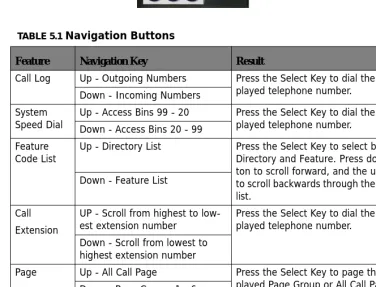
The Navigation Keys, located at the right of the Display, allows quick access to commonly used features. There are 4 navigation keys which circle the activation key. For example, to use the Navigation keys, begin by pressing the Right navigation key, to access Call Log, and then press the down navigation key to view incoming and the up navigation key to view outgoing calls. Press the center activation key to dial the displayed telephone number.
Press the left navigation key to scroll forward, and the right to scroll backwards through the navigation feature list.
TABLE 5.1 Navigation Buttons
Feature Navigation Key Result
Call Log Up - Outgoing Numbers Press the Select Key to dial the dis-played telephone number.
Down - Incoming Numbers System
Speed Dial Up - Access Bins 99 - 20Down - Access Bins 20 - 99 Press the Select Key to dial the dis-played telephone number.
Feature
Code List Up - Directory List Press the Select Key to select between Directory and Feature. Press down but-ton to scroll forward, and the up butbut-ton to scroll backwards through the selected list.
Down - Feature List
Call Extension
UP - Scroll from highest to low-est extension number
Press the Select Key to dial the dis-played telephone number.
Down - Scroll from lowest to highest extension number
Page Up - All Call Page Press the Select Key to page the dis-played Page Group or All Call Page. Down - Page Groups 1 - 6
Music UP - N/A Press the Select Key to enable or Dis-able Background Music
Down - N/A
Door Phone Up - Answer Door Phone 1 The Door Phone must be connected and active to access
Down - Answer Door Phone 2
Fe
at
ur
e C
od
es
5
Feature
Codes
Feature codes may be dialed at the time of operation or they may be stored on a program-mable feature button. Once stored, the feature can be easily accessed by pressing the but-ton. If applicable, the associated LED will light, indicating that the feature is currently operational. For example, Program Do Not Disturb on a feature button, when pressed the associated LED will illuminate, indicating that the extension is in DND mode.
TABLE 5.2 Telephone Feature Codes
Feature Digital Telephone Single Line telephone Access Specific CO Line F 0(x) (x=line 1-9) # 0(x)
Account Code 4 4
Answering Machine Emulation F 64
Attendant 0 0
Attendant Administration F#0
Authority Code F 55 # 55
Automatic Hold Allow F 94 Automatic Selection F 95
Background Music F 52
Busy Ring Allow/Deny F #2
Call Back F 91 #91
Call Forward F 2 #2(y) Y =
0 - Idle Forward 1 - Busy/ No Answer 2 - Direct Forward 3 - Follow Me 4 - No Answer 5 - Busy/No Answer 6 - External
Call Park F 73
Call Pickup Directed F 54 #54
Call Pickup Group F 53 #53
Fe
atu
re
C
od
es
5
Call Wait Allow/Deny F 99
Camp On (Busy Extension) Ext + 2
Camp On (Busy CO Line) #
CO Line Group Access 9 9
Conference F 60
Data Rate F 75
Day/Night Mode F 63 + PPPP
PPPP=Attendant Password Default Flexible Buttons F 58
Default Setting F 69
Directed Call Pick Up F 53 # 53
Distinctive Ring F #7
Do Not Disturb (DND) F 4 # 4
Extension Feature Status F #8 Extension Password - Phone
Lock F97 #97
Extension Reminder F 92 #92
Extension Reminder Delete F*92 #*92
Flash (PBX/CO) F 3 # 3
Flexible Feature button Pro-gramming
F #3
Group Call Pickup F 54 # 54
Headset Enable/Disable F 9#
Hot Dial F #6
Hold Retrieve (SLT) Same
Extension * 6
Hold Retrieve (SLT) Different
Extension * 7 EE EE=Extension
Hot Line # #4
Intercom Call Back F 91
Last Number Redial F 8 #8
Least Cost Routing F 68
TABLE 5.2 Telephone Feature Codes
Fe
at
ur
e C
od
es
5
Message Waiting F 96 # 96 Send
#*96 Cancel Monitor - Extension F 7*
Multiple Mailbox Button F66 + 0 or F66 + 70~79
Mute F 76
Night Mode (Attendant) F 63
Page F 50 # 50(Z) Z=
0 - All Call
1 - External Page Only 2 - System All Call 3 + g - Group All Call g = 1 - 9
Page Allow/Deny F #9
Page Answer (Meet Me) F 59 # 59
Pause F 70
Phone Lock F 97 # 97
Pulse to Tone * *
Relay Control F 61
Save Dialed Number F 51
Security Control F 62
Speed Dialing (Abbr Dialing) F 1
Speed Dialing (SLT) # 1 to store
* 1 to Dial
Status Message F 90
Touch Tone on/off F #1
Transfer Beep F 79
Voice Call Allow/Deny F 98
Voice Mail F 64 #64
Voice Recording F 67
TABLE 5.2 Telephone Feature Codes
Accessing Specific CO Lines
5
Feature
Code
Operation
Accessing
Specific
CO
Lines
Feature 0
(x)
Accessing Individual CO Lines may be accessed directly by pressing the Feature button fol-lowed by 0(x), where (x) = the CO Line 1 - 9. This allows both Single Line and Digital Key telephones the ability to access specific CO Lines rather than dialing the line group code.
Conditions:
1. The CO Line hardware must be installed or the CO Line will not be available.
2. The CO Line must be connected to the telephone company facility or error tone will be heard.
Account
Code
Feature
4
Account Codes can be forced, which requires an extension to enter the account code before placing a CO Line call, or unforced, allowing the user to decide if/when they will enter the account code. All account codes are verified against the “Password Dial Table” (MBC - 5-02) in Restriction.
Answering
Machine
Emulation
Feature
64
Answering Machine Emulation requires the voice mail (VM) System. This feature 'Mimics' the call screening feature of a simple analog answering machine. Within a specified time after a call is answered by an extension user's Voice Mailbox, that user can monitor/screen callers as they leave a message.
Att
end
an
t
5
to retrieve the caller from the voice mail box and be connected to the caller for a live con-versation.
Conditions:
1. To Monitor or Answer a call, action must be taken before the “Monitor Time” expires. 2. Monitor Time starts at the time the caller is connected to the user's voice mailbox. 3. For Answering Machine Emulation to operate, the extension must be forwarded to the
Voice Mail System.
4. Predefined Call Forward or Extension Call Forward can be used for this purpose.
Attendant
Any Digital Key Telephone may serve as the Attendant. The Attendant supports several general system functions like Line Recall, Forced Incoming ICM Call Forward and manual evening or alternate service mode operation as well as Voice Mail Shutdown. The attendant will receive all intercom calls directed to the Attendant Directory Number, (“0” at default).
A second (alternate) attendant position may be selected for common sharing of incoming CO line calls or load sharing during peak traffic periods.
The attendant's extension password allows for control of the system service mode (Day/ Evening/Alternate/Time), time of day settings, (Abbr) System Speed Dial number program-ming, and recording of the optional Auto Attendant greetings. The attendant extension may be connected to any system extension port and be assigned any intercom extension number in the numbering plan.
Associated Features Associated Programming
Voice Mail Extension Predefined Forward 1-SN-21
At
ten
dan
t Admin
istr
ati
on (Admin.
)
5
Attendant
Administration
(Admin.)
Feature #0
Attendant Administration (Admin.) is used to set or modify the features:
•
Service Mode (Day/Alt/Eve/Time)•
Auto Attendant Messages (optional Auto Attendant Module required)•
Temporary Mode•
System Speed Dial•
FWD AUXI LAMPAttendant Administration can be done at any digital key telephone. The Attendant Adminis-tration password is the same as the user's password of the assigned Attendant Extension.
Programming System Speed Dial:
1. To enter a CO Line Flash (“hook-flash”) in a System Speed number, press Feature 3. The stored “hook-flash” is indicated by a “/” character at telephones with displays. For example to enter “FLASH1389” in a system speed number the entry would be: “Feature 3 + 1389“. The displayed system speed number would be “/1389”. 2. To enter a “Pause” in a System Speed Dial, press Feature 70. A stored pause is
indi-cated by a “P” character. For example to enter
“9P01188635773141” into a system speed number the
entry would be “9 + Feature 70 + 001188635773141. The displayed system speed number would be “9P01188635773141”.
3. To chain one speed dial number to another, press Feature 1 the speed dial number location to dial. For example; if a very long telephone number will not fit into one speed number location, split the number into two locations. To store the number
“12345678901234567890”, for example, into locations 20 and 21:
•
Enter into location 20: “1234567890Feature 1 21”. Associated Features Associated ProgrammingService Mode Speed Dial System Automated Attendant Auxiliary Lamp CFW
At
ten
dan
t Ad
ministr
ation
(Admin.
)
5
•
Enter into 21: “1234567890”•
Dial this sequence of numbers by accessing only Speed bin location “20.”•
A maximum of 16 digits can be entered into any one speed bin.Service Mode Switching:
The system can run in one of three modes, Day, Night and Timed. Only the programmed attendant position has the ability to manually change the system from Day to Night, or Night to Day. Once the system is manually placed in either mode, it will remain in that mode until the attendant changes the mode. However, if in timed mode, the system will switch from Day to Night Mode automatically.
The Attendant extension must dial Feature 63 Plus the Attendant Extension Password to switch from Day to Night or Night to Day.
Conditions:
1. The extension User Password programmed for the Attendant extension is required for entry into Attendant Administration, Caller ID Table and Ring Mode
2. Only the designated Attendant extension can manually change the system Ring Mode. 3. The Attendant extension receives all calls via any extension that invokes Forced
Inter-com Call Forward.
Associated Features Associated Programming
Do Not Disturb
Attendant Administration (Feature#0O): Service Mode Change
Auto Attendant Message Record/Review Temporary Service Mode
(Abbr.) System Speed Dial Call Forward Auxiliary Lamp
Resource:
Attendant 4-03
ty
C
ode (
Tra
ve
ling Class of Service)
5
Authority
Code
(Traveling
Class
of
Service)
Feature 55
Authority Codes are used to bring a more privileged Class of Service to an extension with a less privileged Class of Service. When using Authority Codes, the extension password must be entered.
Conditions:
1. Error tone is heard when an invalid account code is entered, and the telephone will return to an idle state.
2. When a valid account code is dialed, the extension is connected to a CO Line, and the Account Code’s Class of Service is verified before a call is placed.
Automatic
Hold
Feature 94
This feature enhances extension users’ productivity and helps eliminate accidental “lost calls” by automatically placing the current call on hold, while answering another CO Line call. For example, when a user is on CO Line 1, and presses CO Line 2, CO Line 1 will be placed on “Exclusive Hold” automatically. Similarly, while on an intercom call and talking with another extension, by pressing a CO Line button, the intercom call will be placed on Exclusive Hold. The need to press Hold is eliminated, except if you want to place a call on System Hold.
Associated Features Associated Programming
Toll Restriction Digit Intervals 5-01 Toll Restriction Password codes 5-02 Extension
Day/Night Class of Service 1-SN-01/02 CO Line
Day/Night Class of Service 2-LN-01/02
Au
toma
tic R
ecord
5
Conditions:
1. The Feature Code (Feature 94) may be programmed under a flexible button on a Digital Speakerphone. To enable/disable the feature, press the flexible button.
2. If you access an idle line and skip to another line before dialing, the first line will not be automatically placed on Hold. (Once a digit is dialed, the line is considered in use, so the automatic hold feature is active.)
3. The Automatic Hold feature places a call on Exclusive Hold.
4. If you have the Automatic Hold feature programmed on a feature button, the feature button lamp will light when the feature is enabled.
Automatic
Record
Feature
67
When a voice mail is installed, the system will permit 8 extensions to be placed into an Automatic Recording group. When this feature is enabled for an extension, the system will record all Central Office conversations automatically whenever the user is on call. The recording will be deleted automatically after the call is released or placed on hold unless the user presses Voice Record Button (Feature 67). All recording are stored in the extension user's mailbox.
Note:
Requires the Voice Mail System
Associated Features Associated Programming
CO Line Group 2-LN-07 Exclusive Hold Feature H
Call Handling
Au
tomatic Selection (CO/I
nter
com)
5
Conditions:
1. The Feature Code “Feature 67“must be programmed under a flexible feature button on the digital speakerphone to be used with the Auto Record feature.
1. Outgoing call recording begins after the Call Duration Timer has expired.
2. Placing a call on hold constitutes completing a call and ends the recording function. If the recorded conversation prior to pressing hold is to be kept, the Voice Record button must be pressed prior to pressing Hold.
3. Auto Record and Voice Record occupy one voice channel on the Voice Mail system dur-ing the record operation. This resource consumdur-ing function should be deployed with careful consideration of the total available voice mail channels and the overall impact on other voice mail/auto attendant Associated functions.
4. Only eight (8) digital key telephones may be assigned for use with the Auto Record fea-ture.
5. Requires the Integrated Voice Mail system.
Automatic
Selection
(CO/Intercom)
Feature 95
This feature automatically selects a specific outside line or intercom (ICM) when the hand-set or the speakerphone button is pressed.
A line will not be accessed automatically when a telephone is receiving an incoming (out-side or intercom) call or when a line is recalling at the telephone. However, the automatic line selection feature may be overridden by pre-selecting an outgoing line, or dialing an extension before lifting the handset, or pressing the speaker button.
Associated Features Associated Programming Voice Mail Digital Integration Voice Mail
Au
xiliary Lamp
LE
D Status Bar
5
Conditions:
1. The system will not allow invalid directory numbers to be programmed during setup. 2. An Extension must have CO Line Access to any CO Line or Line group trying to be
accessed.
Auxiliary
Lamp
LED
Status
Bar
Each Digital Key Telephone is equipped with dual colored LED’s and an Auxiliary Lamp/LED Status Bar to assist users in recognizing the extensions' status. The LED will operate and indicate active CO line ringing, Intercom ringing, Mute, Message Waiting, Speakerphone/ Headset Mode and Call Forward conditions.
Conditions:
1. The lamp may have more than one indication flashing or steady at one time as features are utilized in the system.
2. When “Extension Call Forward” is enabled, the Status Bar will be lit solid.
3. The LED status bar indicates several different functions such as Call Forward, Do Not disturb, or line ringing.
Associated Features Associated Programming
Private Line CO Line Group Ringing Line Priority
Extension
Line Assignment 1-LN-04 CO Line
Ba
ckg
rou
nd
M
usic (B
G
M
)
5
Background
Music
(BGM)
Feature 52
The system comes equipped with one external music source input for Music-On-Hold and Background Music. When a Digital telephone is idle and this feature is activated, the user can monitor background music (BGM) through the telephone speaker. This feature can be activated using a feature code or press the programmed feature button (Feature 52). In addition, the Navigation Key can be used to enable and disable the Music-On-Hold feature.
Conditions:
1. When a flexible button is programmed to activate or deactivate BGM, the associated LED will not light.
2. BGM automatically turns off when an extension user receive or make a call. 3. BGM automatically turns on again when the telephone returns to an idle status. 4. Users with BGM enabled will not hear a system alarm reminder.
Barge
‐
In
(Intrusion)
See Intrusion - Extension
Busy
Lamp
Field
(BLF)
/
Direct
Station
Select
(DSS)
Depending on user requirements, any Programmable Feature Button can be programmed as a BLF button to monitor an extension's status; when an extension is off hook the pro-grammed BLF button LED for that extension lights. When that extension is in Do Not Dis-turb, the LED will flash. This same button is used as a one-button Direct Station Selection (DSS) call button for quick transfer of calls or intercom calling.
Associated Features Associated Programming
Music on Hold
System and Extension Reminder
Busy R
in
g Allow/Den
y
5
Conditions:
1. BLF/DSS buttons may be assigned to any of the 18 User Programmable Flexible But-tons.
2. Extensions in Do Not Disturb mode will cause the LED associated to that extension to flash.
3. Extensions that are busy will cause the LED associated to that extension to light steady. 4. The DSS function can be used to transfer calls to other extensions.
Busy
Ring
Allow/Deny
Feature
#2
This feature allows the extension user the ability to turn on or off muted ringing of incom-ing or transferred calls when the user is in a busy status. When a CO Line is rincom-ingincom-ing or transferred to a busy extension and Busy Ring is allowed, the user will hear muted ringing. When a CO Line is ringing or transferred to a busy extension and Busy Ring is denied, the user will hear a single burst of warning tone. All programmed call forwarding and recall conditions apply in either Busy Ring condition.
Conditions:
1. This feature will toggle on/toggle off when it is programmed under a flexible button on the Digital Speakerphone.
2. The LED will not light when the feature is enabled, or disabled.
Associated Features Associated Programming
Do Not Disturb
Flexible Feature Button Programming One Touch Transfer
Feature Key Programming
Feature Key allow 1-SN-13 System Application Feature Key Copy 4-23
Associated Features Associated Programming
Transfer
Call A
tten
dant
(Op
er
ator)
5
Call
Attendant
(Operator)
0
The extension that is programmed as the Attendant may receive multiple internal calls via the programmed Operator Code “0”.
Conditions:
1. The Operator Code (0) is in addition to the default assigned two-digit intercom number for the extension.
2. The attendant two-digit extension number can be assigned to any feature button.
Call
Back
–
Extension
Feature
91
or Press “cbck”
This feature allows the user to queue an extension, which is busy, in Do Not Disturb (DND) or idle. When a user sends a Call Back to a busy extension, the Call Back process will begin when the busy extension hangs up. When Call Back is sent to an idle extension, the Call Back process will begin once the user performs an operation at that extension and then hangs up.
When the Call Back process begins the user will hear bursts of tone signaling them to pick up the handset or press the LCD soft key under 'reply'. Then the queued extension begins ringing.
Associated Features Associated Programming
N/A Resource Attendant 4-03
Resource Alternate Attendant 4-04
Associated Features Associated Programming
Intercom Mode Selection (F95) Forced Intercom Tone Ring (*) Flexible Button (F#3)
Interactive Soft Buttons
Cal
l Dur
ation Timer (I
ncoming/Outgoing)
5
Conditions:
1. If the user presses [del] during the Call Back Alert ringing, the Call Back will be can-celled and the display will read “CBCK DELETE”. The user’s extension returns to an idle status.
2. To invoke a Call Back at an extension that is in the Voice Announce mode, the user must press Force Tone Ringing (*).
3. When a Call Back alert is not answered at the extension that invoked the Call Back, the display message “CBCK TO EXT” be displayed until either they [reply] or [del]. 4. The Call Back process begins when both the user’s extension and the called party's
extension are idle, on-hook.
Call
Duration
Timer
(Incoming/Outgoing)
This feature is enabled in the Database Programming on a per extension basis. When enabled, any outgoing CO Line call will be automatically timed, then when the system “Warning Tone” time expires, the call is released. This feature is normally used to control outgoing call traffic.
Conditions
1. After the Call Duration Time has expired, the Call Timer begins.
Associated Features Associated Programming
Warning Tone 1-SN-08 Warning Time 3-12
Call
F
orw
ar
d
Extension
5
Call
Forward
Extension
Feature 2
There are several call forward options to choice from; each extension user can customize their own call forwarding.
•
“Idle” Forward all calls,•
“Busy” Forward calls only when the extension is busy.•
“Follow Me” Use the follow me feature to receive calls at a temporary loca-tion and activate the feature remotely from another extension.•
“No Answer” Forward calls that go unanswered at an extension.•
“External” Forward incoming calls to another location or different telephone number. (This feature must be enabled for your extension in database administration.)Forward conditions may be set as follows for each call forward type:
•
Intercom calls only.•
Intercom and CO Line (including transferred CO Lines) calls.•
CO Line calls only.Conditions:
1. Intercom calls to a forwarded extension will receive a special tone signifying that the extension called is forwarded.
2. The Auxiliary Lamp will not light in call forward mode if it has been disabled by the attendant in Attendant Administration.
3. If any of the Call Forward features are programmed on a flexible button, the LED asso-ciated with that button will light indicating that call forward is active.
4. External call forward is programmed in Attendant Administration programming, allowing one inbound CO Line to forward to a preprogrammed, outbound CO Line.
Associated Features Associated Programming
Do Not Disturb (F4) Call Forward (F2) Message Waiting (F96) Forced Intercom Tone Ring (*) Intercom Mode Selection (F98)
Extension
Ca
ll P
ar
k /
Ca
ll P
ar
k A
ns
w
er
5
Call
Park
/
Call
Park
Answer
Feature 73
This feature allows calls to be placed in “Park” at any extension. It also is used to retrieve a parked call from any extension. Calls are parked and retrieved by dialing the Call Park code (Feature 73) followed by the extension number where the call was parked.
Call Park is similar to transferring a call to a hold location, that is accessible from any extension in the system.
Conditions:
1. Each telephone/extension has one personal extension number used to park one CO Line call.
2. Any extension can park a call at another (installed) extension.
3. The Call Park feature code may be programmed on any programmable feature button. 4. Calls can be retrieved from any extension.
5. Parked CO Lines are on Transfer or Exclusive Hold at the extension that placed the call in parked.
6. Any extension can retrieve a “parked” CO line, even if the extension is normally not allowed to access or receive a call on that line.
7. A user invokes “Call Park Answer” and has no CO Line button for the line retrieved from call park may use Hold Call Answer to place the call on hold and retrieve the call from hold.
8. The Call Park Answer feature code may be programmed on any programmable feature button.
9. Calls that are parked follow the Transfer Recall Timer and will ring the initiating exten-sion when that timer has elapsed.
Associated Features Associated Programming
Flexible Button Programming (F#3) Pick up Groups
CO Line Transfer (idle/Busy)