A Novel Design Framework for Structures/Materials with
Enhanced Mechanical Performances
Jie Liu1, Xiaonan Fan2, Guilin Wen1,2*, Qixiang Qing2, Hongxin Wang2,Gang Zhao2
1
Center for Research on Leading Technology of Special Equipment, School of Mechanical and Electric Engineering, Guangzhou University, Guangzhou 510006,P. R. China
2State Key Laboratory of Advanced Design and Manufacturing for Vehicle Body,
Hunan University, Changsha 410082, P. R. China
* Corresponding author. Tel: +86 731 88823929; Fax: +86 731 88822051
E-mail address: glwen@gzhu.edu.cn (Guilin Wen)
Abstract
Structure/material requires simultaneous consideration of both its design and
manufacturing processes to dramatically enhance its manufacturability, assembly and
maintainability. In this work, we present a novel design framework for
structure/material with requested mechanical performances in virtue of the compelling
properties of topological design and origami techniques. The framework comprises
four procedures, including topological design, unfold, reduction manufacturing, and
fold. Topological design method, i.e. Solid Isotropic Material Penalization (SIMP)
method, serves to optimize the structure to achieve preferred mechanical
characteristics and origami technique is exploited to make the structure rapidly and
easily fabricated. Topological design and unfold procedures can be conveniently
completed in a computer; then, reduction manufacturing, i.e. cutting, is performed to
remove materials from the unfolded flat plate; the final structure is finally obtained by
folding the plate of the previous procedure. A series of cantilevers, consisting of
origami with parallel creases and Miura-ori (usually regarded as a metamaterial),
made of paperboard are designed with least weight and required stiffness by using the
proposed framework. The findings here furnish an alternative design framework for
engineering structures which could be better than 3D printing technique, especially
for large structures made of thin metal materials.
Keywords: design and fabrication framework; origami; topological design
1.Introduction
The product design process is normally divorced from the manufacturing process,
leading to the extremely poor manufacturability, assembly and maintainability of the
product. Thus, simultaneously considering the design and manufacturing processes is
desired in actual engineering.
The specific functionalities and mechanical performances of the product need to
be taken into account according to its service environment during the design process.
This can be rather a simple task for structural optimization techniques [1]. Structural
optimization methods can be broadly divided into three categories, namely, size
optimization [2], shape optimization [3,4], and topology optimization [5-11] methods.
The main difference among the three methods is the design variables and the design
freedom. Compared with the former two methods, topology optimization is a
challenging and active research field, which can produce various innovative
candidates with expected mechanical properties. Since the inception of the
homogenization method [5], this field has received a growing level of attention,
emerging a series of methods, including density-based methods, hard-kill methods,
boundary variation methods, and so forth. Among them, Solid Isotropic Material
Penalization (SIMP) method [5], Evolutionary Structural Optimization (ESO) method
[7] and its improved version Bi-directional Evolutionary Structural Optimization
(BESO) method [12,13], and Level-set method [8-10] are recognized as the most
widely used, which have been applied in various fields, covering aerospace [14],
multifunctional materials [15-17], biomedical design [18,19], uncertain design
[20-22], etc.
Traditionally, engineers utilize reduction manufacturing method to fabricate
engineering structures, which will significantly waste materials in most cases. To this
end, 3D printing [23], as a kind of rapid prototyping technology, based on a digital
model file and the use of powder metal or plastic bonding material, through layer by
layer printing method to construct objects, has again gotten engineers' attention
recently due to its myriad merits, such as saving in material, producing structures with
highly complex geometries, et al. Although 3D printing has been successfully applied
in automotive, aerospace, medical industries, civil engineering, and other fields
[24-26], it has its limitations at the present, i.e., being relatively too expensive and
inefficient, the limited available material and manufacturing size, having accuracy and
industry and reduction manufacturing method is still the mainstream in the future.
Alternatively, one structure/material can be created by using origami technique
[27,28]. Origami is an ancient art such that it transforms a flat sheet of paper into a
finished sculpture through folding along predefined creases. Inspired by its
compelling and extraordinary features, origami technique has been imitated and
utilized to design metamaterials [29,30], self-folding structures [31], sandwich
structures [32], mechanisms [33], and energy absorbing structures [34-35], etc.
Research into topological design for rigid foldable origami structures [36,37] mainly
determine where to put the crease lines on the initial flat plane on the basis of the
displacement response. Size optimization for the origami-based structures has also
been observed. However, layout design for origami-based structures to look for the
optimal material distribution has rarely been studied.
In this study, we try to tap the virtues of topological design and origami
techniques to propose a novel design framework for structures. This framework can
provide a fast design method for structures with predominantly mechanical
performances, especially for large structures made from thin metal plates. We here
first investigate the design of simple origami-based cantilevers, and then use the
framework to design more complex origami-based cantilevers, i.e. Miura-ori-based
cantilevers.
2.Materials and Methods
2.1 Testing
Dynamic mechanical analysis is performed to characterize the paperboard,
making up the origami-based cantilevers, by using a DMA Q800 machine. During the
test, the temperature is about 24 °C and the humidity is close to 50% RH. Stress scan
method is used with force increasing from 0.05 to 10 N, with a logarithmic scale and
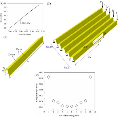
1 Hz force modulation. The stress-strain curve reported in Fig. 1a indicates that the
paperboard with thickness t=0.32mm is characterized by a Young’s modulus
Ep=27.05GPa (Fig. 1A). It should be pointed out that for all the paperboard a
Fig. 1. (A) The stress-strain curve for the paperboard, (B) the geometry for one
unit cell of the origami with parallel crease lines, (C) the geometry, boundary, and
loading conditions for the origami-based cantilever, and (D) the corresponding
compliance of cutting holes in different facet.
2.2 Geometrical dimensions
Origami can be constructed by periodic arranged units. A unit consists of two
identical rectangles (facet) with length, L=250mm, and width, B=20mm, and one
crease (see Fig. 1B). The dihedral angle is formed between two facets, α=60°.For
simplicity and without loss of generality, we consider an origami with five units and
mark the facets from No.1 to No. 10 (see Fig. 1C).
2.3 Finite element simulations
Finite element (FE) simulations are performed to investigate the deflection
behaviors of the origami-based cantilevers by using the commercial package
elements (S4R). The size of the shell element is 2×2mm. For the finite element model,
its left boundary is fixed and five concentrated forces with equal magnitude, P=5 N,
are applied to its right side (see Fig. 1C). The analysis method in Abaqus is static.
2.4 Topology optimization
In actual engineering, structure with high stiffness-weight ratio is always the
pursuit of the engineers, especially in the aviation field. Here, we use the
computational approach, continuum topology optimization method, to design the
layout of patterns to yield a structure with the aforementioned mechanical
performance. Specially, the weight of the origami-based cantilever is minimized and
its stiffness is restrained. For each design problem, two non-design domains, Dnon,
highlighted in Fig.2A, are defined to maintain the integrity of the final optimal
structure. The rest of the origami-based structure is defined as design domain, Ddes.
This design domain can be occupied by solid elements or void elements.
Normally, continuum topology optimization problem can be mathematically
formulated as
1 0 ,..., ,..., ,..., 1 , 0 ,..., 1 , 0 : to Subject : Minimize min T 1 e N e j i t j h m i g f ρ ρ ρ ρ (1)where f
is the objective function. g
and h
are the inequality and equalityconstraints, respectively. m and t represent the number of the inequality and
equality constraints, respectively. e stands for the design density which ranges
from min (normally, min 0.001) to 1. N is the number of the elements
occupying the design domain, Ddes.
In this study, the minimum weight is desired and the maximal deflection is
restrained. Since homogeneous material is used, minimizing structural weight is
equivalent to minimizing the structural volume and limiting the maximal deflection is
equivalent to imposing a restriction on the structural compliance. The equality
constraint is the structural static equilibrium equation. Thus, the objective function,
f , the inequality constraint, g
, and the equality constraint, h
,can berespectively written as
ρ V(ρ)
ρ CC(ρ)0g (3)
ρ PK
ρU ρ 0h (4)
where V
is the volume. C
and C are the structural compliance and apredefined limit for the structural compliance, respectively, and C
ρ PU
ρ . Pindicates the vector of the applied load. K and U are the structural stiffness matrix
and the vector of the displacement, respectively.
Using the penalty scheme [5], the Young’s modulus of the eth element can be
expressed as
s p e
e E
E (5)
where Es is the Young’s modulus of the solid element and p is the penalization
factor which usually has a value of 3.
The optimization model defined in Eq. (1) is solved by general optimization
algorithm implemented in Abaqus. The filter technique [38] is employed to prevent
the checkerboard problem. In order to make the optimal structure easily fabricated,
the minimum and maximum thickness of the member size is controlled, which can be
realized by using geometric restriction in Abaqus. The optimization iteration
procedure will be terminated when either the change of adjacent element densities or
objective functions meets a prescribed convergence criterion.
2.5 Design and Fabrication framework
Topological design method, in conjunction with origami techniques forms a fast
and efficient design and manufacturing strategy which can yield structures with
desired mechanical performances. The strategy mainly consists of four procedures,
namely, topological design, unfold, reduction manufacture, and fold, as shown in Fig.
2B. Topological design and unfold procedures can be completed via using computer,
together named virtual design; while reduction manufacturing and fold are real
manufacturing procedures.
3.Results
3.1 Deflection behavior of the origami-based cantilever
To study the influence of removing materials on the deflection behavior of the
origami-based cantilever, we cut small holes in each facet. The holes may have
different shapes and numbers. For the sake of simplification, we only focus on the
b=60mm and a width a=12mm (see Fig. 1C).
The deflection behavior may be the primary consideration for the engineering
structures. Generally, the deflection is determined by the structural stiffness in the
elastic stage and the structural stiffness is the reciprocal of the structural compliance.
Thus, we employ structural compliance, C, to characterize the deflection behavior of
the origami-based cantilever.
Fig.2. (A) The initial design and non-design domain for the origami-based
cantilever, and (B) the proposed design and fabrication framework.
Fig. 1D shows the structural compliance of origami-based cantilevers with
rectangle hole cutting in various facets, highlighted from No.1 to No.10. The
corresponding compliance is 38.9108 N·mm, 38.7049 N·mm, 38.6878 N·mm, 38.663
N·mm, 38.6577 N·mm, 38.6577 N·mm, 38.663 N·mm, 38.6878 N·mm, 38.7049
N·mm, and 38.9108 N·mm respectively, manifesting that cutting materials from the
structure may have great influence on structural stiffness. Hence, we can attempt to
find ways to restrict the deflection of the structure by removing materials
quantificationally and directionally. Topology optimization can control the structural
maximal deflection at the same time yield structure with desired performance, i.e.
3.2 Design and fabrication of the origami-based cantilevers
Fig.3. (A) Optimal designs for the origami-based cantilever under various
constraints, and (B) applying the proposed framework to the origami-based cantilever.
Fig. 3A shows a series of optimal origami-based cantilevers obtained from the
topology optimization with various limits for the structural compliance. The minimum
and maximum thickness of the member size is controlled as 6mm and 7mm,
respectively. The convergence criterion for the adjacent element densities and
objective functions is 0.005 and 0.001, respectively. For the non-design domain,
L1=L2=6mm. It can be clearly found that the final layout and the final volume of the
origami-based cantilever significantly differ from each other with different constraints.
N·mm, 42 N·mm, and 43 N·mm, respectively. It is easy to understand that more
materials will be removed from the initial design domain when the restraint for the
structural compliance becomes larger, leading to the lighter weight of the
origami-based cantilever. We will choose the first design to demonstrate our proposed
framework.
Fig.4. (A) Geometry for the unit cell of the Miura-ori, and (B) the geometry,
boundaries, and loading conditions for the Miura-ori-based cantilever.
Fig. 3B presents the novel design and fabrication framework for the chosen
origami-based cantilever. Apparently, the framework includes: 1) establish the finite
element model of the origami-based cantilever in Abaqus; 2) perform the continuum
topology method to optimize the cantilever, and get the optimal design; 3) unfold the
optimal design with specific patterns; 4) Cut holes in the paperboard to obtain the
patterns; 5) use the origami technique to fold the paperboard, achieving the real
origami-based cantilever with intended mechanical performance. It should be noted
that the first two procedures are completed in Abaqus, and the third procedure is
finished in Solidworks, and the last two procedures are accomplished manually.
Using the proposed framework, we attempt to design and fabricate more
complex origami-based cantilevers. Here, the famous Miura-ori is selected. Fig. 4
shows the geometry, boundaries, and loading conditions for the Miura-ori-based
cantilever. For the geometry, the Miura-ori consists of 36 unit cells. One unit cell (see
Fig. 4A) is formed by four parallelograms, and each parallelogram has sides a and b
and acute angle γ. The dihedral angle between two parallelograms is ø. The outer
dimensions, like l, w, and h can be determined by the equations in reference [39]. The
models are divided with 3D shell elements (S4R). Each element has a size of 2×2mm.
Its left boundary is fixed and six concentrated forces with equal magnitude, P=5 N,
are applied to its right side (see Fig. 4B). It should be noted that Miuta-ori-based
structure is always considered to be rigid-foldable. Here, we consider the facet as
deformable plate as the applied loads are assumed relatively small.
In the topological design, the minimum and maximum thickness of the member
size is selected as 4.5mm and 6mm, respectively. The convergence criterion for the
adjacent element densities and objective functions is set as 0.005 and 0.001,
respectively. Fig. 5A shows the optimal designs of the Miura-ori-based cantilevers.
Similarly, more materials have been omitted from the initial design domain when the
restraint for the structural compliance becomes larger, resulting in lighter weight of
the Miura-ori-based cantilever. Specifically, the final volume is 11535.7 mm3, 11400.6
mm3, 11226 mm3, and 11050.6 mm3 when the predefined limit of the structural compliance is 89.1 N·mm, 90 N·mm, 91 N·mm, and 92 N·mm, respectively.
We choose the first design of the Miura-ori-based cantilever to give evidence of
our proposed design and fabrication framework. Fig. 5B depicts the whole procedures
of our framework. After establishing the finite element modeling of the
Miura-ori-based cantilever, the design goal and constraints are given and the
topological design is performed. The optimal design is obtained, and later we unfold it
in a 3D modeling software, i.e. Solidworks. Whereafter, we cut the holes in the
paperboard to get the patterns the same with that obtained from the 3D modeling
software. Finally, we use the origami technique to fold the paperboard at the
predefined crease lines, and we achieve the real Miura-ori-based cantilever with
Fig.5. (A) Optimal designs for the Miura-ori-based cantilever under various
constraints, and (B) applying the proposed framework to the Miura-ori-based
cantilever.
4. Discussion and future work
The design and fabrication for the origami-based cantilevers successfully
demonstrate the feasibility and effectiveness of our proposed framework. The
Miura-ori. The framework is preferred for structures made of thin material. The
desired mechanical performances are not restricted to the minimum weight and the
limit on the structural stiffness. Mechanical characteristics like maximum natural
frequency, largest stiffness, etc. can be also sought.
We here manually cut the materials from the paperboard. An alternative way to
increase precision would be to use laser cutting that would produce accurate holes. To
promote our framework for practical engineering applications, metal thin materials,
i.e. aluminum, should be used to make the real origami-based cantilevers.
Unfortunately, since the thickness of the metal affecting the folding process, the real
metal origami-based cantilevers can be difficult to make. To facilitate folding, at the
crease lines the material may be locally thinned by means of chemical etching. The
real metal origami-based cantilevers could be manufactured by using a cold gas
pressure folding technique [39]. However, this method may only be suitable for small
scale structures as it is not an easy task to produce uniform pressure to fold large
metal structures. Future work will attempt to use the framework to design and
fabricate large engineering structures made of thin metal materials, in particular
stainless steel.
5.Conclusion
In this paper, we have presented a novel framework for designing engineering
structures/materials with intended mechanical performances by combining the
compelling merits of topological design and origami techniques. The framework
comprises four procedures, including topological design, unfold, reduction
manufacturing, and fold. Specifically, topological design method serves to optimize
the structure to achieve preferred mechanical characteristics and origami technique is
exploited to make the structure rapidly and easily fabricated. We use one simple
origami with parallel creases and one complex Miura-ori based cantilevers to validate
the effectiveness of the proposed framework. The minimum weight of the structure
with restrained stiffness is achieved via topological design and the real structure is
easily made by using the folding technique. This framework can be applied to design
and fabrication of large engineering structures made of thin metal materials, is
inexpensive and quick to fabricate, compared with 3D printing techniques. It should
be noted that the proposed framework is not restricted to design and make cantilevers;
Acknowledgements
This research was financially supported by the National Natural Science Foundation
of China (No. 11672104, 51705092). We thank Prof. Mike Xie and Dr. Eric Xu from
RMIT University for their help in conducting the DMA test.
References
[1] Haftka, R.T.; Zafer G. Elements of structural optimization. Vol. 11. Springer Science & Business Media, 2012.
[2] Anindyajati, A.; Boughton, P.; Ruys, A.J. modelling and optimization of Polycaprolactone ultrafine-fibres electrospinning process using response surface methodology. Materials. 2018, 11(3), 441.
[3] Sokolowski, J.; Zolesio, J.P. Introduction to shape optimization. In Introduction to Shape Optimization. Springer, Berlin, Heidelberg, 1992, 5-12.
[4] Noël, L.; Duysinx, P. Shape optimization of microstructural designs subject to local stress constraints within an XFEM-level set framework. Struct. Multidiscip. O.2017, 55(6), 2323-2338.
[5] Bendsøe, M.P.; Sigmund, O. Material interpolation schemes in topology optimization. Arch. Appl. Mech.1999, 69(9), 635-654.
[6] Bendsøe, M.P.; Kikuchi, N. Generating optimal topologies in structural design using a homogenization method. Comput. Method. Appl. M. 1988, 71(2), 197-224.
[7] Xie, Y.M.; Steven, G.P. A simple evolutionary procedure for structural optimization. Comput. Struct.1993, 49(5), 885-896.
[8] Wang, M.Y.; Wang, X.; Guo, D. A level set method for structural topology optimization. Comput. Method. Appl. M.2003, 192(1), 227-246.
[9] Zhang, W.; Yuan, J.; Zhang, J.; Guo, X. A new topology optimization approach based on Moving Morphable Components (MMC) and the ersatz material model.
Struct. Multidiscip. O.2016, 53(6), 1243-1260.
[10]Kang, Z.; Wang, Y. Structural topology optimization based on non-local Shepard interpolation of density field. Comput. Method. Appl. M. 2011, 200(49), 3515-3525.
[11]Rong, J.H.; Liang, Q.Q. A level set method for topology optimization of continuum structures with bounded design domains. Comput. Method. Appl. M.
2008, 197(17), 1447-1465.
[12]Huang, X.; Xie, Y.M. Convergent and mesh-independent solutions for the bi-directional evolutionary structural optimization method. Finite Elem. Anal. Des.2007, 43(14), 1039-1049.
[13]Rong, J.H.; Jiang, J.S.; Xie, Y.M.. Evolutionary structural topology optimization for continuum structures with structural size and topology variables. Adv. Struct. Eng.2007, 10(6), 681-695.
[14]Zhu, J.H.; Zhang, W.H.; Xia, L.Topology optimization in aircraft and aerospace structures design. Arch. Comput. Method. E.2016, 23(4), 595-622.
microstructures for maximized stiffness and fluid permeability. Int. J. Solids Struct.2016, 43(22), 7028-7047.
[16]Osanov, M.; Guest, J.K. Topology optimization for architected materials design.
Annu. Rev. Mater. Res.2016, 46, 211-233.
[17]Zuo, Z.H.; Huang, X.; Rong, J.H.; Xie, Y.M. Multi-scale design of composite materials and structures for maximum natural frequencies. Mater. Design 2013, 51, 1023-1034.
[18]Sutradhar, A.; Park, J.; Carrau, D.; Nguyen, T.H.; Miller, M.J.; Paulino, G.H. Designing patient-specific 3D printed craniofacial implants using a novel topology optimization method. Med. Biol. Eng. Comput.2016, 54(7), 1123-1135. [19]Wang, X.; Xu, S.; Zhou, S.; Xu, W.; Leary, M.; Choong, P.; ; Xie, Y.M.
Topological design and additive manufacturing of porous metals for bone scaffolds and orthopaedic implants: a review. Biomaterials 2016, 83, 127-141. [20]Liu, J.; Wen, G.; Xie, Y.M. Layout optimization of continuum structures
considering the probabilistic and fuzzy directional uncertainty of applied loads based on the cloud model. Struct. Multidiscip. O.2016, 53(1), 81-100.
[21]Wang, L.; Liu, D.; Yang, Y.; Wang, X.; Qiu, Z. A novel method of non-probabilistic reliability-based topology optimization corresponding to continuum structures with unknown but bounded uncertainties. Comput. Method. Appl. M.2017, 326, 573-595.
[22]Csébfalvi, A.; Lógó, J. A critical analysis of expected-compliance model in volume-constrained robust topology optimization with normally distributed loading directions, using a minimax-compliance approach alternatively. Adv. Eng. Softw. doi: 10.1016/j.advengsoft.2018.02.003.
[23]Yang, Y.; Chen, Y.; Wei, Y.; Li, Y. 3D printing of shape memory polymer for functional part fabrication. Int. J. Adv. Manuf. Tech.2016, 84(9-12), 2079-2095. [24]Rengier, F.; Mehndiratta, A.; von Tengg-Kobligk, H.; Zechmann, C.M.;
Unterhinninghofen, R.; Kauczor, H.U.; Giesel, F.L. 3D printing based on imaging data: review of medical applications. Int. J. Comput. Ass. Rad. 2010, 5(4), 335-341.
[25]Bose, S.; Vahabzadeh, S.; Bandyopadhyay, A. Bone tissue engineering using 3D printing. Mater. Today2013, 16(12), 496-504.
[26]Bhushan, B.; Caspers, M. An overview of additive manufacturing (3D printing) for microfabrication. Microsyst. Technol.2017, 23(4), 1117-1124.
[27]Chen, Y.; Peng, R.; You, Z. Origami of thick panels. Science 2015, 349(6246), 396-400.
[28]Teoh, J.E.M.; An, J.; Feng, X.; Zhao, Y.; Chua, C.K.; Liu, Y. Design and 4D Printing of Cross-Folded Origami Structures: A Preliminary Investigation.
Materials2018, 11(3), 376.
[29]Silverberg, J.L.; Evans, A.A.; McLeod, L.; Hayward, R.C.; Hull, T.; Santangelo, C.D.; Cohen, I. Using origami design principles to fold reprogrammable mechanical metamaterials. Science2014, 345(6197), 647-650.
[31]Felton, S.; Tolley, M.; Demaine, E.; Rus, D.; Wood, R. A method for building self-folding machines. Science2014, 345(6197), 644-646.
[32]Baranger, E.; Guidault, P.A.; Cluzel, C. Numerical modeling of the geometrical defects of an origami-like sandwich core. Compos. Struct. 2011, 93(10), 2504-2510.
[33]Hanna, B.H.; Lund, J.M.; Lang, R.J.; Magleby, S.P.; Howell, L.L. Waterbomb base: a symmetric single-vertex bistable origami mechanism. Smart Mater. Struct.
2014, 23(9), 094009.
[34]Song, J.; Chen, Y.; Lu, G. Axial crushing of thin-walled structures with origami patterns. Thin.Wall. Struct.2012, 54, 65-71.
[35]Yang, K.; Xu, S.; Shen, J.; Zhou, S.; Xie, Y.M. Energy absorption of thin-walled tubes with pre-folded origami patterns: Numerical simulation and experimental verification. Thin.Wall. Struct.2016, 103, 33-44.
[36]Fuchi, K.; Diaz, A.R. Origami design by topology optimization. J. Mech. Des.
2013, 135(11), 111003.
[37]Fuchi, K.; Buskohl, P.R.; Bazzan, G.; Durstock, M.F.; Reich, G.W.; Vaia, R.A.; Joo, J.J. Origami actuator design and networking through crease topology optimization. J. Mech. Des.2015, 137(9), 091401.
[38]Sigmund, O.; Petersson, J. Numerical instabilities in topology optimization: a survey on procedures dealing with checkerboards, mesh-dependencies and local minima. Struct. Multidiscip. O.1998, 16(1), 68-75.