Strata
®
DK
Technical Bulletin
726+,%$
4031051
Upgrading to Strata DK424 Release 4.x
This bulletin provides instructions for replacing a Strata DK14, DK16e, or DK40 system with a DK424 system, Release 4.x (which includes Release 4.0 and higher). It also explains how to upgrade a DK280 or DK424 system, Release 1, 2, 3, 3.1 and 3.2 to a DK424 system, Release 4.x. The following important items must be considered when performing the above changes and/or upgrades.
A new feature added in DK424 Release 4.x is increased station capacity in systems containing Tie and Direct Inward Dialing (DID) lines. In Release 4.x, the station capacity of systems that contain Tie/DID lines increases due to Release 4.x eliminating automatic assignment of station ports to DID and Tie lines. Tie and DID lines provided by RDDU, RDTU, RPTU, REMU, and PEMU PCBs do not use station ports with DK Release 4.x and above. However, ISDN BRI PCBs, RBUS/RBSS and RBUU/RBUS do use two station ports for each circuit (line side or station side).
This bulletin also provides instructions and examples of how DKAdmin/DKBackup, Release 4.0 or higher, adjusts for station port shifting caused by Tie and/or DID lines when upgrading to DK424, Release 4.x software and above. This phenomenon occurs only when upgrading to DK424 Release 4.x processors from DK Release 1~3.2 systems that have station PCBs installed in higher numbered slots than Tie/DID line PCBs.
Step 1: Determine the Upgrade Configuration
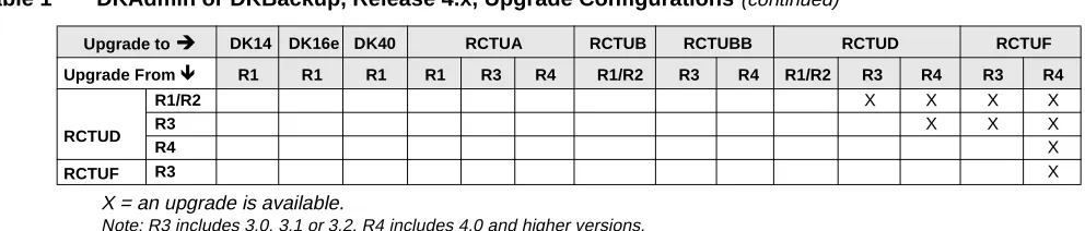
Table 1 shows the different Strata DK upgrade possibilities using the Release 4.0 or higher versions of DKAdmin/DKBackup. For example, you can upgrade from an RCTUA, R3 to an RCTUBB, R4; however, you cannot upgrade an RCTUA, R3 to an RCTUD, R1/R2.
Table 1 DKAdmin or DKBackup, Release 4.x, Upgrade Configurations
Upgrade toÍ DK14 DK16e DK40 RCTUA RCTUB RCTUBB RCTUD RCTUF
Upgrade From Ï R1 R1 R1 R1 R3 R4 R1/R2 R3 R4 R1/R2 R3 R4 R3 R4
DK16e R1 X X X X X X X X X
DK40 R1 X X X X X X X X
RCTUA
R1 X X X X X X X X X X
R3 X X X X X X X
R4 X X X
RCTUB R1/R2 X X X X X X X
RCTUBB R3 X X X X X
R4 X X
TBDK-0027 Begin the DKAdmin or DKBackup Procedure
For additional information, refer to bulletin TBDK-0009 and the Strata DK CD-ROM Library or the Strata DK Installation and Maintenance Manual and Programming Manual for information on Release 4.x.
Step 2: Begin the DKAdmin or DKBackup Procedure
You must use DKAdmin or DKBackup Release 4.0, or higher, for this procedure. Prior releases of these programs do not provide Strata DK Release 4.x Upload/Download/Upgrade capabilities. The latest version of DKAdmin or DKBackup is available for download from the Toshiba FYI internet sit.
1. Using DKAdmin or DKBackup Release 4.0, or higher, download the customer data from the currently installed processor. Save this “Customer” data as a backup in case you must re-install the current processor and/or processor ROM/flash memory release level.
2. Using DKAdmin or DKBackup, create a new customer for the upgrade.
Important! When creating the new customer, select the currently installed processor type and release level—not the Release levels or the processor you are “upgrading to.” Select R3 in DKAdmin/DKBackup for Rel. 3.0, 3.1, 3.2 to 3.x. Select R4 for Strata DK Rel. 4.0 up to Rel. 4.x.
3. Using DKAdmin or DKBackup, select the customer created in Step 2 (not Step 1).
4. Use the Upgrade (F5) function from the Backup/RestoreData menu to start the upgrade procedure.
5. Choose “Yes” when prompted to BackupFromDKFirst.
6. After the current data is downloaded, follow the DKAdmin/DKBackup screen instructions to change the processor and/or ROMs or flash memory and re-initialize. The procedure for changing ROMs and flash memory is provided in figures on the following pages of this bulletin.
Important! When changing the processor and ROM or flash memory for the “Upgrade to” processor, you can add one RSIU to complete the upgrade at 9600 bps. However:
● Do not add new station or Tie/DID line PCBs.
● Do not change the order in which the PCBs are installed in the slots.
● Be sure to re-initialize the “Upgrade to” processor twice and set the DK TTY port with Programs 76 and 03.
RCTUD
R1/R2 X X X X
R3 X X X
R4 X
RCTUF R3 X
X = an upgrade is available.
Note: R3 includes 3.0, 3.1 or 3.2. R4 includes 4.0 and higher versions.
Table 1 DKAdmin or DKBackup, Release 4.x, Upgrade Configurations (continued)
Upgrade toÍ DK14 DK16e DK40 RCTUA RCTUB RCTUBB RCTUD RCTUF
TBDK-0027 Install the Upgrade ROMs
P
reli
min
ary and
Conf
iden
tial
Step 3: Install the Upgrade ROMs
1. Power down the system before removing and installing the PCB(s).
Figure 1 shows the slot placement of the processor cards. Remove only the RCTUA, RCTUBB,
RCTUD, or RCTUF.
2. Remove the MOH connection, if required.
3. Remove the RRCS DTMF PCB on the RCTU card, if equipped (see Figures 2~5).
Figure 2 RCTUA PCB
RCTUBB, RCTUA, or RCTUD
RCTUD only To RSIU if installed
RCTUBA or RCTUC
Slot R11 Slot RCTU (Base Cabinet) P3 P2 P11 P2 Heartbeat LED 1394 RCTUF
To RSIU if installed
RCTUE
Slot R11 Slot RCTU (Base Cabinet) P3 P2 P11 P2 Heartbeat LED 1924
Figure 1 RCTU PCB Removal and Component Placement
P5 P4 BATT ON OFF P3 P2 P11 VR1 CBRUK IC12 Feature Upgrade Connectors (not used)
TBDK-0027 Install the Upgrade ROMs
Figure 3 RCTUB4.X PCB
Figure 4 RCTUD4.X PCB
Figure 5 RCTUF4.X PCB
IC10
P1
Program ROMS
IC9, 10, 11, and 12
RCTUBB4.X
P3 P2
IC9
Ribbon Cable to RCTUBA (and RSIU if installed) Ribbon Cable to RCTUBA RBA4-0 RBA4-9 RBA4-2 RBA4-1 IC12 IC11 RCTUBB4.X 4132 Upgrade Label Software Version R4.X = P8 P7 P6 P5 IC10 P1 Program ROMS
IC9, 10, 11, and 12
To RCTUC To RCTUC
(and RSIU, if installed)
P3 P2 IC9 U3 U4 RCA4-0 RCA4-9 RCA4-2 RCA4-1 IC12 IC11 Software Version R4 = Software Version R4 = Software Version R4 =
BATT ON P9OFF
RCTUD4.X Upgrade Label RCTUD4.X 4133 P9 P10 4134 UP UP RMMS REA4X
To RCTUE To RCTUE (and RSIU, if Installed)
P8 P2 P3 BATT ON OFF P5 Upgrade Label RCTUF4.X RCTUF4.X Software
Version R4.X = X 2 H
TBDK-0027 Install the Upgrade ROMs
P
reli
min
ary and
Conf
iden
tial
4. Using a small screwdriver to carefully remove the four ROMs (see Figure 6) or use your fingers togently remove the flash memory. Replace with the equivalent ROMs or flash memory in the upgrade kit. Peel the labels (two locations) off the card.
5. Re-install the RRCS DTMF PCB, if required.
Note If there are battery straps on the PCB, make sure that they are placed in the “on” position for the processor card(s) to avoid losing your data.
6. Re-insert the processor card(s), reconnect the ribbon cables and MOH connection if necessary. If an RSIU card is being added, shift the card positions accordingly, add the RSIU PCB in slot 11 and change the ribbon cable to connect the RCTU PCB(s) to the RSIU.
Note any changes needed to accommodate the displaced card if necessary. If this creates extensive changes, it may be better to upgrade without adding the RSIU, get the system working, and then adjust the card positions to add the RSIU card.
7. Turn the Strata DK system back on and follow the DKAdmin/DKBackup instruction screens for completing the upgrade.
(back) Designates Front of Chip
Front Direction Marker Silk-screened on PCB
IC Socket Mounted on Processor's PCB (front)
Turn Very Gently
2514
Do Not Break IC Socket
Do Not Scratch PCB
CAUTION! Be careful not to break the IC socket or scratch the PCB trace.
TBDK-0027 Complete the DKAdmin or DKBackup Procedure
Step 4: Complete the DKAdmin or DKBackup Procedure
➤ Continue with the DKAdmin or DKBackup upgrade procedure as prompted by the DKAdmin or DKBackup screens until complete.
Important! After you install Release 4.x software on an RCTU PCB, you must initialize the RCTU and re-program the customer database. (See following procedures.)
Note An upgrade example at the end of this bulletin describes what changes take place in the customer data during the DKAdmin/DKBackup upgrade procedure to make the upgrade transparent to the end user.
DK424 Release 4.x Upgrade Programming Example
Important! When upgrading to DK424 Release 4.x from a lower release, it is highly recommended to use the DKAdmin or DKBackup Release 4.0, or higher, PC software program. The DKAdmin and DKBackup Release 4.0, or higher, upgrade process performs all the necessary program port and code changes automatically. Trying to upgrade to Release 4.x manually from the programming telephone could take many hours.
The following Release 3 to Release 4.x upgrade example shows basic programming changes automatically made by DKAdmin/DKBackup due to station port shifting. Station port shifting only occurs when station PCBs are in higher numbered slots than Tie and/or DID lines.
This example doesn’t provide every program change required, nor does it attempt to instruct you on how to re-program a system upgraded to Release 4.x via the programming telephone. This is a simple system upgrade; actual installed system upgrades can be much more complex.
Cabinet Station Port Counting Before/After Release 4.x Upgrade
Figure 7 shows the DKAdmin cabinet drawing of a DK424 system with an:
♦ RCTUE3/F3 processor
♦ RSIU interface
♦ 16 digital telephones
♦ 4 analog DID lines
Notice that the RDDU PCB increments the station ports by four ports.
Figure 7 Cabinet Drawing for RCTUE3/F3 Before Release 4.x Upgrade
PCB Placement per Program 03
Cabinet 1 R11 RCTU S11 S12 S13 S14 S15 S16
PCB Type RCTUE3 RCTUF3 RSIU PDKU2 RDDU PDKU2
Port Nos. 000~007 008~011 012~019
Line Nos. 001~004
TBDK-0027 Complete the DKAdmin or DKBackup Procedure
P
reli
min
ary and
Conf
iden
tial
Figure 8 shows the same DKAdmin cabinet drawing after upgrading to an RCTUE3/F4 with DKAdmin.
Notice that the telephones connected to the PDKU2 in slot 14 were on ports 012~019 but are now on ports 008~015, respectively. This phenomenon requires many programming changes to enable the Strata DK system to operate the same as it did prior to the upgrade. DKAdmin/DKBackup Release 4.0, or higher, is designed to make all programming changes automatically to enable the upgrade to be transparent to the system operation.
Figure 8 Cabinet Drawing for RCTUE3/F3 After Release 4.x Upgrade
System/Station Administration Screen Before/After Release 4.x Upgrade
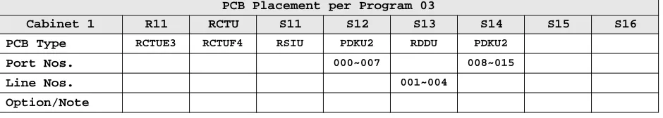
Figure 9 shows the DKAdmin System/Station Administration Screen of the same DK424 Release 3 system
shown in Figure 7.
Figure 9 System/Station Administration Screen for RCTUE3/F4 Before Release 4.x Upgrade PCB Placement per Program 03
Cabinet 1 R11 RCTU S11 S12 S13 S14 S15 S16
PCB Type RCTUE3 RCTUF4 RSIU PDKU2 RDDU PDKU2
Port Nos. 000~007 008~015
Line Nos. 001~004
Option/Note
System/Station Administration
CSN (Cabinet Slot No.)
Phy. Port
No. PT
Telephone Location
Log Port
No.
Int/ PDN No.
Telephone LCD User Name
VM CF Id Code
TBDK-0027 Complete the DKAdmin or DKBackup Procedure
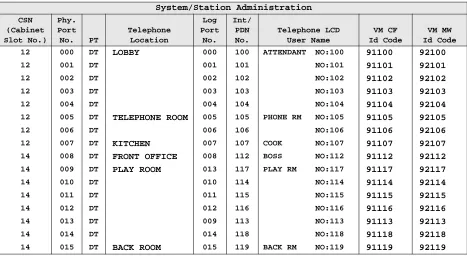
Figure 10 shows the same system after upgrading to RCTUE3/F4 with DKAdmin.
Figure 10 System/Station Administration Screen for RCTUE3/F4 After Release 4.x Upgrade
The following summarizes the changes (from Figure 9 to 10 ) after the upgrade.
This type of phenomenon must occur on all Strata DK Programs that contain port numbers to provide a transparent upgrade.
Program Changes Before/After Release 4.x Upgrade
The following examples show the type of programs and data that must change when upgrading from DK14/DK16e/DK40 Release 1 and DK280/DK424 Release 1~Release 3 to DK424 Release 4.x. These program changes are required to make the Strata DK operate the same after the upgrade as it did before; thus making the upgrade transparent to the end user. The changes apply to all DK424 Release 4, RCTU processors: RCTUA, RCTUB, RCTUBA/BB, RCTUC/D, and RCTUE/F.
Basically, any program that has station ports as data needs to change if the station port numbers are higher than the pre-upgrade DID/Tie line port numbers. The examples shown here represent the types of Strata DK programs that require changes when upgrading to Release 4.x. They are not meant to show all programs since the principles of program changes are the same for each program type.
System/Station Administration
CSN (Cabinet Slot No.)
Phy. Port
No. PT
Telephone Location
Log Port
No.
Int/ PDN No.
Telephone LCD User Name
VM CF Id Code
VM MW Id Code 12 000 DT LOBBY 000 100 ATTENDANT NO:100 91100 92100
12 001 DT 001 101 NO:101 91101 92101
12 002 DT 002 102 NO:102 91102 92102 12 003 DT 003 103 NO:103 91103 92103
12 004 DT 004 104 NO:104 91104 92104
12 005 DT TELEPHONE ROOM 005 105 PHONE RM NO:105 91105 92105
12 006 DT 006 106 NO:106 91106 92106
12 007 DT KITCHEN 007 107 COOK NO:107 91107 92107
14 008 DT FRONT OFFICE 008 112 BOSS NO:112 91112 92112 14 009 DT PLAY ROOM 013 117 PLAY RM NO:117 91117 92117
14 010 DT 010 114 NO:114 91114 92114
14 011 DT 011 115 NO:115 91115 92115
14 012 DT 012 116 NO:116 91116 92116
14 013 DT 009 113 NO:113 91113 92113
14 014 DT 014 118 NO:118 91118 92118 14 015 DT BACK ROOM 015 119 BACK RM NO:119 91119 92119
Before the Upgrade After the Upgrade
RDDU in Slot 13 Ports 008~011 as DL (or DID) ports Deleted Port Range of PDKU2 in Slot 14 Ports 012~019 Ports 008~015 Slot 14 User Names, PDNs, and DID
TBDK-0027 Complete the DKAdmin or DKBackup Procedure
P
reli
min
ary and
Conf
iden
tial
When upgrading to a DK424 Release 4.x (and above), the programming changes can be complex when a system has DID and Tie lines. The following examples show the program changes required whenupgrading RCTUE3/F3 to RCTUE3/F4. The DKAdmin Cabinet Drawing and System/Station Administration Screen for this example are provided in Figures 7~10.
Programs 01 and 02
These programs show the relationship between physical and logical ports. When upgrading to Release 4.x, these relationships remain the same unless ports have been swapped prior to the upgrade. If the swapped port numbers shift during the upgrade, they must be renumbered in programs 01 and 02. If the swapped ports do not shift during the upgrade, they remain the same after the upgrade.
In this system configuration, ports 013 and 017 are swapped prior to the upgrade (see Figure 8). After the upgrade, port 013 shifts to 009 and 017 shifts to 013 (see Figure 9, therefore after the upgrade port 009 is swapped with port 013. Notice that before and after the upgrade, the Play Room telephone is on the second PDKU circuit in slot 14 and to call the Play Room Telephone you must dial 117 - making the upgrade transparent to the end user.
Program 03
There is no change to the data in this program when upgrading to Release 4.x; however the RDDU DID lines are not allocated ports after the upgrade (see Figures 8 and 10).
Program 04
Data in this program must be changed to adjust for port shifting caused by the RDDU DID line PCB in slot 13 (see Figures 9 and 10):
Programs
04, 05, 09
There is no change to the data in these programs when upgrading to Release 4.x. Note that DID/Tie ports do not cause Phantom DN ports to shift in Strata DK Release 1~Release 3 systems, so they do not shift in Program
04 when upgrading to Release 4.x. Also, the data in Program 09 is DN numbers and not port numbers, so data in Program 09 does not change when upgrading to Release 4.x.
Program
09
Data in this program must be changed to adjust for port shifting caused by the RDDU DID line PCB in slot 13 (see Figures 9 and 10):
Programs 10-1 through 10-4
There is no change to the data in these system programs when upgrading to Release 4.x. Port numbers are not assigned to system programs so no adjustments are necessary.
Before the Upgrade After the Upgrade
Port 000-007; Data 100-107 Port 000-007; Data 100-107 Port 008-015; Data 108-115 Port 008-015; Data 112-119 Port 016-019; Data 116-119 Port 016-019; Data Blank
Before the Upgrade After the Upgrade
TBDK-0027 Complete the DKAdmin or DKBackup Procedure
Program 13
If the Message Center is the Front Office Telephone (PDN 112), data in this program must be changed to adjust for port shifting caused by the RDDU DID line PCB in slot 13 (see Figures 9 and 10):
♦ Data for Program 13 before the upgrade = 012
♦ Data for Program 13 after the upgrade = 008
If the Message Center is the Lobby Telephone (PDN 100), data in this program must not be changed to adjust for port shifting caused by the RDDU DID line PCB in slot 13. This is because Port 000 did not shift after the upgrade (see Figures 9 and 10):
♦ Data for Program 13 before the upgrade = 000
♦ Data for Program 13 after the upgrade = 000
Programs 15, 16, and 17
There is no change to the data in these programs when upgrading to Release 4.x. These are CO line programs and port numbers are not assigned in them so no adjustments are necessary.
Program
17
If the DID Intercept Destination is the Back Room Telephone (PDN 119), data in this program must be changed to adjust for port shifting caused by the RDDU DID line PCB in slot 13 (see Figures 9 and 10):
♦ Program
17 data for DID lines 001~004 before the upgrade = 019
♦ Program
17 data for DID lines 001~004 after the upgrade = 015
If the DID Intercept Destination is the Kitchen Telephone (PDN 107), data in this program must not be changed to adjust for port shifting caused by the RDDU DID line PCB in slot 13. This is because Port 007 did not shift after the upgrade (see Figures 9 and 10):
♦ Program
17 data for DID lines 001~004 before the upgrade = 007
♦ Program
17 data for DID lines 001~004 after the upgrade = 007
Program 20
If the Front Office Telephone (PDN 112) is equipped with an RPCI-DI to display DNIS and Caller ID on a PC running a TAPI application, the data in Program 20 must shift. This enables the Front Office Telephone and RPCI to operate the same way after the upgrade as it did before. Notice that all Program 20 data for port 012 moves port to 008.
Before the Upgrade After the Upgrade
TBDK-0027 Complete the DKAdmin or DKBackup Procedure
P
reli
min
ary and
Conf
iden
tial
Program 30If the Back Room Telephone (PDN 119) is programmed to dial forced and verified Account codes when making outside calls, the data in Program 30 must shift. This enables the Back Room Telephone to operate the same way after the upgrade as it did before. Notice that all Program 30 data for port 019 moves to port 015.
Program 33
If the Front Office telephone (DN 112) is programmed to hunt to the Back Room Telephone (PDN 119), the data in Program 33 must shift:
If the Front Office telephone (PDN112) is programmed to hunt to the Lobby Telephone (PDN 100), the data in Program 33 must shift:
Program
33
If the Back Room telephone (PDN 119) is programmed as the Owner of PhDN 500, the data in Program
33 must shift:Programs 39, 29,
29, and 59
When a port number shifts from XXX to YYY during an Release 4.x upgrade, the following Program changes must be made:
♦ In Program 39, the data set for port XXX must be copied over the data set for port YYY.
♦ In all Telephone/Console button programs, the appearances of the XXX port PDN/SDN Button (##XXX) and DSS Button (#XXX) must be changed to ##YYY and #YYY, respectively, on all keystrips.
Example: The Front Office Telephone changes from port 012 to port 008 during the Release 4.x upgrade, (see Figures 9 and 10). As shown below, all the button functions of the Front Office Telephone do not change after the upgrade, but the Program 39 codes for PDN, SDN and DSS buttons change if the
associated PDN/SDN or DSS port shifts. Also PhDN, Speed Dial, and Feature button codes do not change when ports shift.
Before the Upgrade After the Upgrade
Port 015 LED 01, 05, and 07 ON, all others off
(Program 30 default) LED 01, 05, 07, 08, and 14 ON, all others off Port 019 LED 01, 05, 07, 08, and14 on, all others off LED 01, 05, and 07 on, all others off
(Program 30 default)
Before the Upgrade After the Upgrade
Hunt-From Port 012 to Port 019 Hunt-From Port 008 to Port 015
Before the Upgrade After the Upgrade
Hunt-From Port 012 to Port 000 Hunt-From Port 008 to Port 000
Before the Upgrade After the Upgrade
TBDK-0027 Complete the DKAdmin or DKBackup Procedure
Programs
42-1 and
42-2
Although this example does not include an RDTU (T1) PCB, it should be noted that these programs require an RDTU slot number entry with Strata DK Release 4.x and above software. A slot number is not required in these programs prior to Release 4.x. DKAdmin/DKBackup automatically inserts the correct slot number for these programs during the upgrade process.
10-Button Keystrip for Front Office Telephone on Port 012 -Before Upgrade
10-Button Keystrip for Front Office Telephone on Port 008 -After Upgrade
Key No. Code Name Key No. Code Name
K10 497 SDS K10 497 SDS
K09 498 DND K09 498 DND
K08
103 SD103 K08 103 SD103K07
102 SD102 K07 102 SD102K06
101 SD101 K06 101 SD101K05 #017 DSS117 K05 #013 DSS117
K04 ##500 PhDN 500 K04 ##500 PhDN 500
K03 ##019 SDN 119 K03 ##015 SDN 119
K02 #000 DSS100 K02 #000 DSS100