Stator Resistance Estimation Utilizing Real
and Reactive Power for Direct Torque
Controlled Induction Motor Drives
Dr. A.Venkadesan
1, Dr.K.Sedhuraman
2Assistant Professor, Dept. of EEE, National Institute of Technology Puducherry, Karaikal, India1
Assistant Professor, Dept. of EEE, MVIT, Puducherry, India2
ABSTRACT: In this paper, a new method is proposed to estimate the Stator Resistance for direct torque control of Induction Motor. Direct Torque control of Induction Motor (IM) requires accurate estimation of torque, flux angle and resultant flux and these signals in turn depends on the motor flux. The flux is generally estimated using voltage model equations. The voltage model equation to a large extent depends on the accuracy of stator resistance of the induction motor. The stator resistance varies due to temperature during motor operation. Hence a method based on the active and reactive power is proposed for stator resistance estimation. The effect of stator resistance variation on the flux, torque and flux angle is studied and the results obtained are presented. The proposed method of stator resistance estimation is shown to track the various %changes in stator resistance with good accuracy.
KEYWORDS:Stator Resistance Estimation, Active power, Reactive Power, Induction Motor, Direct Torque Control (DTC), Flux estimator.
I.INTRODUCTION
Induction motor is popularly used for many applications because its construction is simple and it requires less maintenance [1]-[4]. Recent advances in power semiconductor and Microprocessor technology has made possible the application of advanced control techniques to alternating current (AC) motor drive systems. Direct Torque Control (DTC) has become a popular technique for the control of induction motor (IM) drives as it provides a fast dynamic torque response [5], [6]. The performance of DTC to a large extent depends on the knowledge of feedback signals namely torque, flux angle and resultant flux. These signals in turn depend on the accuracy of flux estimation. The voltage model is generally preferred for flux estimation as it requires voltage and current for computation. The voltage model equations depend on the stator resistance. The Stator resistance varies with temperature during the motor operation and introduces error in flux estimation. This in turn introduces large error in the flux angle and torque. This would deteriorate the overall performance of the drive. Hence on-line estimator is required to track variation in stator resistance. Numerous methods for stator resistance estimation are proposed in the literature and it forms an active area of research. The stator resistance estimation utilizing the rotor flux error is proposed [7]. Model reference adaptive system scheme with stator current as state variable is proposed in [8], [9]. The neuro-fuzzy method utilizing stator current is proposed in [10]. The observer based technique utilizing the stator current is proposed [11]. Recently, power based methods are becoming popular. A method using real power is proposed in [12]-[14]. A method utilizing both real and reactive power is proposed [15]. This method is applied only for temperature monitoring of the machine and not applied for drives applications. In this paper, the same approach is applied for stator resistance estimation for flux estimator in direct torque controlled IM drives which is the novelty of this paper. The models are built in MATLAB/Simulink. The proposed method is shown to track variation in stator resistance very well with good accuracy through simulation.
II.DIRECT VECTOR CONTROLLED IM DRIVES
estimator differs from the actual value. The effect of stator resistance variation on the instantaneous fluxes, flux angle, torque is studied. For the study, 50% step change in the stator resistance is applied at 1sec. The investigation is carried out at a low frequency under the load torque of 1Nm as the stator resistance variation is more significant at low frequency. The d and q-axis fluxes, flux angle, torque obtained are presented in Fig. 2, Fig. 3, Fig.4 and Fig.5 respectively. From the results obtained, it is observed that as soon as the step change in stator resistance is applied at 1 sec, the d-axis flux, q-axis flux, flux angle and electromagnetic torque deviates from the actual. This in turn leads the drive system become unstable. This necessitates the need for stator resistance estimator.
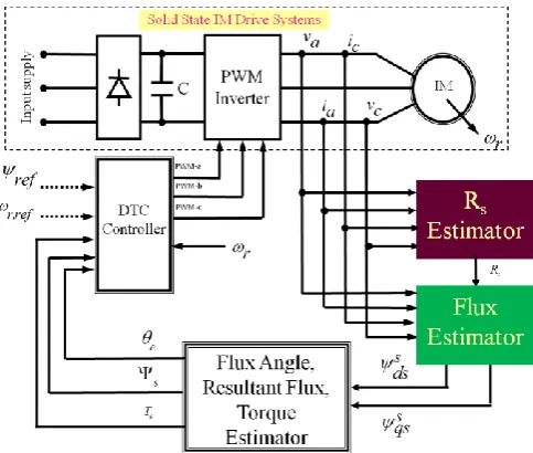
Fig. 1. Basic block diagram of DTC Showing the importance of Stator Resistance Estimator
Fig. 1 describes the importance of various estimators in direct torque controlled IM drives especially stator resistance estimator. The correct stator resistance estimation assumes importance for the proper operation of the drive. If there is a mismatch between the value of the stator resistance in flux estimator and the actual value in the machine, then this will introduce error in the fluxes and this in turn introduces error in the feedback signals namely flux angle, resultant flux and torque. This leads to performance deterioration of the complete drive system.
1
tan qs
e
ds
(1)
2 2
s ds qs
(2)
3 4
e ds qs qs ds
P
T i i (3)
s s s
ds Vds R Is ds dt
(4)
s s s
qs Vqs R Is qs dt
0.4 0.6 0.8 1 1.2 1.4 1.6 1.8 2 -1
-0.5 0 0.5 1 1.5
TIME
S
TA
TO
R
F
L
U
X
STATOR FLUX OF MACHINE STATOR FLUX OF ESTIMATOR
Fig.2. d-axis stator flux
Fig. 2 shows the d-axis rotor flux for stator resistance variation. The curve indicated in blue colour is the actual and the curve indicated in red colour is the estimated one. The d-axis flux tracks the actual flux when the value of stator resistance in the flux estimator matches with the actual one. When there is a mismatch at 1sec, the estimated d-axis flux fails to track the actual.
0.5 1 1.5 2
-1 -0.5 0 0.5 1 1.5
TIME
S
TA
TO
R
F
L
U
X
STATOR FLUX OF MACHINE STATOR FLUX OF ESTIMATOR
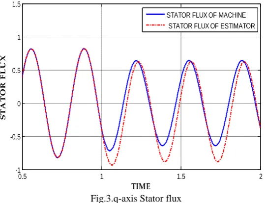
Fig.3.q-axis Stator flux
0.4 0.6 0.8 1 1.2 1.4 1.6 1.8 2 -4 -3 -2 -1 0 1 2 3 4 5 TIME F IE L D A N G L E
FIELD ANGLE OF MACHINE FIELD ANGLE OF ESTIMATOR
Fig.3.Flux Angle
Fig. 4 shows the flux angle for stator resistance variation. The curve indicated in blue colour is the actual and the curve indicated in red colour is the estimated one. The flux angle deviates from the actual when there is change in stator resistance at 1sec.
0.4 0.6 0.8 1 1.2 1.4 1.6 1.8 2 0.5 1 1.5 2 2.5 3 TIME TO R Q U E
TORQUE OF MACHINE TORQUE OF ESTIMATOR
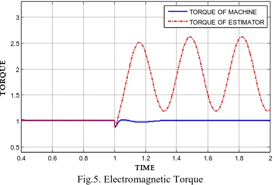
Fig.5. Electromagnetic Torque
Fig. 5 shows the resultant flux for stator resistance variation. The curve indicated in blue colour is the actual and the curve indicated in red colour is the estimated one. The resultant flux also deviates from the actual and oscillation is observed, when there is change in stator resistance at 1sec.
III. PROPOSED METHOD
The proposed method uses both real and reactive power of the motor [15]. The stator resistance can be estimated using the equation (6)-(9)
2
2 2 2
max max max
s s s
r
P Q M Q
R L L
L
I I I
(6)
ds ds qs qs
PV I V I (7)
ds qs qs ds
QV I V I (8)
2 2 2
max ds qs
IV. STATOR RESISTANCE ESTIMATION USING PROPOSED METHOD
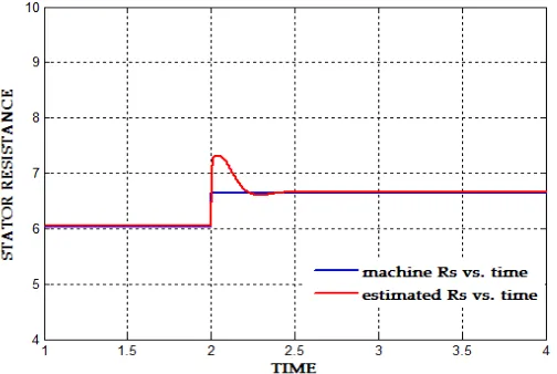
The performance of estimator designed using the proposed method is tested for various %changes in stator resistance. The motor is modelled using d-q dynamic model equations to incorporate variation in the stator resistance. The step change in stator resistance is effected at 2 sec. The step change is the worst case condition used to show the ability of the proposed estimator to track variation in parameter even in the extreme case condition. The results obtained for 10%, 30% and 50% change is presented in the Fig. 6, Fig. 7 and Fig. 8 respectively. The %error and settling time for various %changes in stator resistance is consolidated and presented in Table 1. From the results obtained, it is clear that the proposed stator resistance estimator estimate the stator resistance with the maximum Error and settling time of 0.36% and 0.5 sec.
Fig.6. Actual and Estimated Stator Resistance for 10% change in Rs
Fig. 6 shows the performance of proposed stator resistance estimator for 10% change. The curve indicated in blue colour is the actual and the curve indicated in red colour is the estimated one. The estimated stator resistance closely tracks the actual one very well and settles down quickly as soon as the step change in stator resistance is effected at 1 sec.
Fig. 7 shows the performance of proposed stator resistance estimator for 30% change. The curve indicated in blue colour is the actual and the curve indicated in red colour is the estimated one. The estimated stator resistance closely tracks the actual one very well and settles down quickly as soon as the step change in stator resistance is effected at 1 sec.
Fig. 8 shows the performance of proposed stator resistance estimator for 50% change. The curve indicated in blue colour is the actual and the curve indicated in red colour is the estimated one. The estimated stator resistance closely tracks the actual one very well and settles down quickly as soon as the step change in stator resistance is effected at 1 sec.
Table 1 Performance of Proposed Stator Resistance Estimator
%Rs Actual Rs in ohm Estimated Rs in ohm % Error Settling time
10% 6.33 6.55 0.33 0.5
20% 7.236 7.260 0.33 0.5
30% 7.839 7.866 0.33 0.5
40% 8.442 8.471 0.34 0.37
50% 9.045 9.078 0.36 0.37
Table 1 shows the performance of stator resistance estimator for various changes in stator resistance. The error is found to be almost negligible.
V.CONCLUSION
In this paper, a different approach utilizing real and reactive power is proposed to estimate the Stator Resistance for flux estimator in direct torque controlled IM drives. The results are simulated using MATLAB/simulink 7.0. The performance of proposed Rs estimator is shown to track variation in Rs very well with good accuracy and settling time.
Hence the proposed method is suitable for flux estimator in DTC drives.
REFERENCES
[1] Venkadesan, A., Himavathi, S., and Muthuramalingam, A., “Performance Comparison of Neural Architectures for On-Line Flux Estimation in Sensor-Less Vector Controlled IM Drives”, Springer Journal on Neural Computing and Applications, Vol. 22, No. 7-8, pp. 1735–1744, 2013.
[2] Venkadesan, A., Himavathi, S., Muthuramalingam, A., “Novel SNC-NN-MRAS Based Speed Estimator for Sensor-less Vector Controlled IM Drives,” International Journal of Electrical and Electronics Engineering (WASET)”, Vol. 5, No. 02, pp.73-78, Nov. 2010.
[3] Sedhuraman, K., Himavathi, S., and Muthuramalingam, A., “Neural Learning Adaptive System Using Simplified Reactive Power Reference Model based Speed Estimation in Sensorless Indirect Vector Controlled Induction Motor Drives”, Archives of Electrical Engineering, Vol. 62, No.1, pp. 25-41, 2013.
[6] Tole, S., Nik Rumzi Nik Idris, Auzani Jidin, Marcian N. Cirstea “An Improved FPGA Implementation of Direct Torque Control for Induction Machines” IEEE Transactions on Industrial Informatics, Vol.9, No.3, pp.1280-1290, 2013.
[7] Turki, Y. A., Haroution, A. H., Adel M. D., “Fuzzy logic Based Stator Resistance Estimator For a Direct Torque Controlled three-phase Induction Motor”, Al.muthanna Journal For Engineering Sciences, Vol.2, No.1, pp. 66-81, 2013.
[8] Karanayil, B., Rahman, M.F., and Grantham, C., “Stator and Rotor Resistance Observers for Induction Motor Drive Using Fuzzy Logic and Artificial Neural Networks”, IEEE Transactions on Energy Conversion, Vol. 20, No. 4, pp.771-780, Dec. 2005.
[9] Karanayil, B., Rahman, M.F., and Grantham,C., “Online Stator and Rotor Resistance Estimation Scheme Using Artificial Neural Networks for Vector Controlled Speed Sensorless Induction Motor Drive”, IEEE Transaction on Industrial Electronics, Vol. 54, No. 1, pp. 167-176, 2007. [10] Jaalam, N., Haidar, A.M.A., Ramli, N.L., Ismail, N.L, and Sulaiman, A.S.M, “A Neuro-fuzzy Approach for Stator Resistance Estimation of
Induction Motor”, Proceedings on International Conference on Electrical, Control and Computer Engineering, pp. 394-398, June 2011. [11] Zaky, M., Khater, M., Yasin, H., Shokralla, S S., “A Very Speed Sensorless Induction Motor Drive with On-Line Stator Resistance
Identification Scheme”, Journal of Electrical Systems, Vol.4, No.1, pp. 106-125, 2008.
[12] Mustafa, A., Ibrahim Okumus, H., “Stator resistance estimation using ANN in DTC IM drives”, Turk J Elec Eng & Comp Sci., Vol. 18, No. 2, pp. 197-210, 2010.
[13] Chandan Chakraborty., Ravi Teja, A.V., Suman Maiti., Yoichi Hori., “A New V ×I Based Adaptive Speed Sensorless Four Quadrant Vector Controlled Induction Motor Drive”, International Power Electronics Conference, pp.3041-3048, 2010.
[14] Aswathy Vijay., Binojkumar, A., “Speed and Stator Resistance Estimation of Four Quadrant Vector Controlled IM Drives”, International Journal of Advanced Research in Electrical, Electronics and Instrumentation Engineering, pp. 329-337, 2014.
[15] Huang Weili., HuangWeijian., Liu Lin., “Estimation of Stator Resistance and Temperature Measurement in Induction Motor Using Wavelet Network”, Proceedings of the 26thChinese Control Conference, pp.203-207, 2007.
APPENDIX
The parameters of the three-phase induction motor used for simulation are presented below,
Parameters Values Parameters Values
Rated Power Rated voltage Rated current Type Frequency Number of poles Rated Speed 1.1kW 415V 2.77A 3 Ph 50Hz 4 1415RPM
Stator Resistance (Rs)
Rotor Resistance (Rr)
Magnetizing Inductance (Lm)
Stator Inductance (Ls)
Rotor Inductance (Lr)
Total Inertia (JT)
Friction Coefficient (B) 6.03Ω 6.085Ω 0.4893H 0.5192H 0.5192H 0.011787Kgm2 0.0027Kgm2/s
Nomenclature
( )
s s ds qs
V V - Stator voltages d axis (q axis) P -real power in watts
( )
s s ds qs
I I - Stator currents d axis (q axis) Q -reactive power in watts
( )
s s ds qs
- Stator flux d axis (q axis) -Angular Frequency in rad/sec
s
R - Stator resistance in ohms r -Rotor Speed in rad/sec
e
- Flux Angle in radians Ls -Stator Inductance in Henry
s
- Resultant Flux in wb M -Mutual Inductance in Henry
e
T -Electromagnetic Torque Imax -maximum quantity of phase current in Ampere