Perceptions & ex
DiGITAL PBX
INSTALLATION AND MAINTENANCE MANUAL
DIGITAL
PBX
SECTION
200-255-000
FEBRUARY
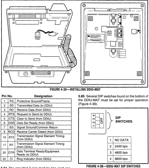
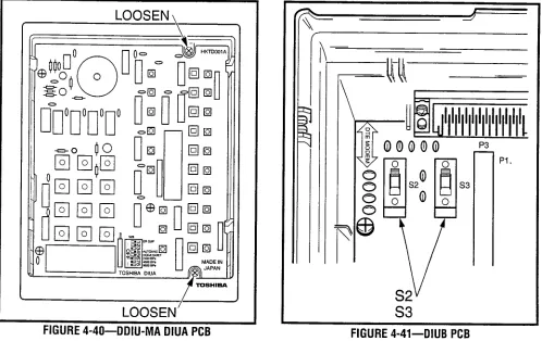
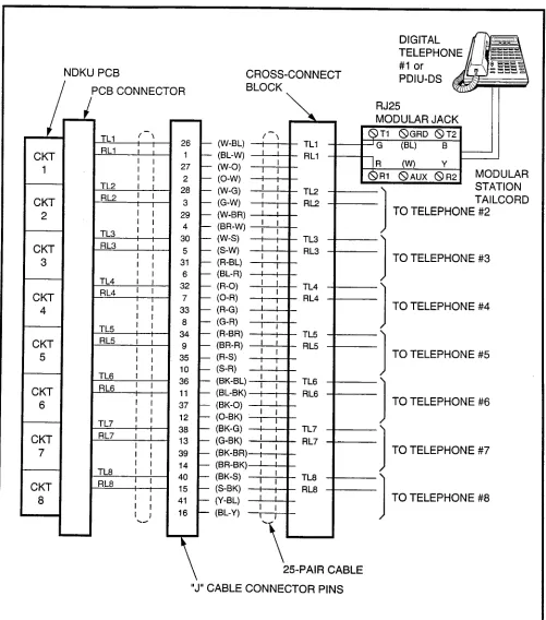
1992
Perception&
a ex
DIGITAL
PBX
INSTALLATION AND MAINTENANCE MANUAL
TABLE OF CONTENTS
GENERAL DESCRIPTION
INSTALLATION INSTRUCTIONS
PROGRAMMING PROCEDURES
FAULT FINDING PROCEDURES
TECHNICAL BULLETINS
TOSHIBASYSTEM
PRACTICES
DIGITAL
PBX
INSTALLATION
SECTlON200-255-200
INSTRUCTIONS
FEBRUARY1992
Perception&
65 ex
DIGITAL
PBX
SECTION
200-255-200
FEBRUARY
1992
PERCEPTION,&,
INSTALLATION INSTRUCTIONS
TABLE OF CONTENTS
PARAGRAPH
SUBJECT
PAGE
CHAPTER1 1. 2. 3. 4. 5. 5.00 5.10 5.20 CHAPTER2 1. 1.00 1.10 1.20 2. 2.00 2.10 2.20 3. 4. 5. 6.
INTRODUCTION . . . ...*... PURPOSE . . . ORGANIZATION . . . REFERENCE DOCUMENTATION . . . SYSTEM MNEMONICS . . . INSPECTION, PACKING AND STORAGE . . . Inspection . . . Packing and Storage . . . Required Tools . . . SYSTEM DESCRIPTION ... PERCEPTION e ... Basic Equipment Cabinet ... Expansion Cabinet ... Power Supply ... PERCEPTION ex ... Basic Equipment Cabinet ... Expansion Cabinet ... Power Supply ... PEAK LOAD BATTERY ... EXTENDED RESERVE POWER ... POWER FAILURE/EMERGENCY TRANSFER ... PRINTED CIRCUIT BOARD DESCRIPTION.. ... NFDU (Floppy Disk Drive Unit). ... LCCU (Central Control Unit) ... NTWU (Time Switch Unit) ... NPRU (Paging and Music-on-Hold Unit) ... NRCU (Receiver Unit) ... NEKU (Electronic Telephone Unit) ... NDKU (Digital Telephone Unit). ... NSTU (Standard Telephone Unit) ... NDSU (DSS Console Controller Unit) ... NDCU (Data Control Unit) ... NMDU (Modem Pooling Unit) ... NCOU (Central Office Trunk Unit) ... NEMU (E & M TIE Trunk Unit). ... NLSU (DID Trunk Interface Unit). ... NDTU (Tl Interface) ... NOCU (Off-hook Call Announce Interface Unit) ... HVSUHVSI (Off-hook Call Announce PCBs) ... DVSI (Digital Off-hook Call Announce PCB) ...
INSTALLATION
INSTRUCTIONS
SECTION
200-255-200
FEBRUARY
1992
PARAGRAPH
SUBJECT
PAGE
7. a. a.00 a.10 a.20 a.30 a.40 a.50 8.60 a.70 8.80 a.90 CHAPTER 3
1. 2. 3. 4. 5.
CHAPTER 4 1. 1 .oo 1.10 2. 2.00 2.10 2.20 3. 3.00 3.10 3.20 3.30 3.40 3.50 3.60
SYSTEM INDICATORS AND CONTROLS . . . NFDU . . . LCCU . . . NTWU . . .
NPRU . . .
NCOU/NEMU/NLSU
. . .
NDTU . . .
NEKU/NSTU/NOCU/NDKU
. . .
NDSU . . .
NDCU . . .
NMDU ...
NPSA-M/LPSA-M ...
N PSA-S ...
PERIPHERAL EQUIPMENT ...
Electronic and Digital Telephone ...
Headset Upgrade (HHEU) ...
Attendant Console ...
DSS Console ...
Standard Telephone ...
DDIU/PDIU ...
Paging Equipment ...
Music-on-Hold ...
Universal Night Answer ...
Station Message Detail Recording ...
2-7
‘.
2-7 2-7 2-7 2-7 2-7 2-7 2-a 2-a 2-a 2-a 2-a 2-a 2-a 2-a 2-9 2-9 2-9 2-9 2-9 2-9 2-9 2-9 2-9 INSTALLATION SITE REQUIREMENTS . . . 3-1COMMERCIAL POWER
. . . 3-1 ENVIRONMENTAL REQUIREMENTS . . . 3-1 EQUIPMENT ROOM RECOMMENDATIONS . . . 3-1 CABLING CONSIDERATIONS . . . 3-1GROUNDING . . .
3-2SYSTEM INSTALLATION ...
PERCEPTlONe ...
Power Supply Installation ...
Expansion Cabinet Installation ...
PERCEPTIONex ...
Power Supply Installation ...
First Expansion Cabinet Installation ...
Second Expansion Cabinet Installation ...
PRINTED CIRCUIT BOARD INSTALLATION.. ...SECTION
200-255-200
FEBRUARY
1992
PARAGRAPH
SUBJECT
PAGE
3.70 3.80 3.90 4. 5. 5.00 5.10 5.20 5.30 5.40 5.50 5.60 5.70 5.80 5.90 6. 6.00 6.10 6.20 6.30 6.40 6.50 6.60 6.70 6.80 6.90 6.100 6.110 6.120 6.130 6.140 6.150 6.160 6.170 6.180 7. 7.00 8.00 9. 9.00 9.10 9.20 9.30 9.40 9.50 9.60 9.80
NEMU, NCOU, and
NLSU...
NDTU ...
NMDU and NDCU ...
CABLE CONNECTIONS ...
ELECTRONIC TELEPHONE STATION EQUIPMENT INSTALLATION..
...
Electronic Telephone Connections.. ...
Electronic Telephone Wall Mounting ...
Off-hook Call Announce ...
Carbon Handset Transmitter Installation ...
HHEU Installation ...
Attendant Console Connection ...
DSS Console Connections ...
Digital Data Interface Unit Connections (DDIU) ...
DDIU-MAT ...
DDIU-MA ...
DIGITAL TELEPHONE STATION EQUIPMENT INSTALLATION ...
Digital Telephone Connections..
...
Digital Telephone Wall Mounting .. . ...
Off-hook Call Announce ...
Carbon Handset Transmitter Installation ...
Beep Strap Removal ...
Microphone/Speaker
Threshold Adjustment (Speakerphone only) ...
HHEU Installation ...
Attendant Console Connection ...
DSS Console Connections ...
Digital Data Inter-face
Unit Installation (PDIU) ...
Common DIU Connections.. ...
EIA Interface Leads (Signals) ...
DIP Switch Options.. ...
PDIU-DI Installation ...
PDIU-DI to Personal Computer (PC) Installation..
...
PDIU-DS to Printer Installation ...
PDIU-DS to Modem Installation.. ...
PDIU-DS Disassembly and Assembly.. ...
PDIU-DVPDIU-DS
Installation Tests ...
STANDARD TELEPHONE EQUIPMENT INSTALLATION
...
Standard Telephone Connections ...
TRUNK CONNECTIONS ...
PERIPHERAL EQUIPMENT INSTALLATION..
...
Modem Pooling Connections (DDIU-MA only) ...
Power Failure/Emergency
Transfer.. ...
Reserve Power ...
Paging Equipment ...
Music-on-Hold ...
Universal Night Answer ...
Station Message Detail Recording ...
Lodging/Health Care Data Audit.. ...
INSTALLATION
INSTRUCTIONS
SECTION
200-255-200
FEBRUARY
1992
PARAGRAPH
SUBJECT
PAGE
IO.
SYSTEM POWER UP . . . 4-67 10.00 General . . . 4-67 CHAPTER 5 MDF ARRANGEMENT . . . 5-ITABLE
5-I 5-2 5-3 5-4 5-5 5-6 5-7 5-8 5-9 5-10 5-1 I 5-12 5-13 S-14 s-15FIGURE
2-I 2-2 2-3 2-4 2-5 2-6 2-7 2-8 3-I 3-2 3-3 4-I 4-2 4-3 4-4 4-5TABLE LIST
SUBJECT
PAGE
CARD SLOT/CABLE CONNECTOR MATRIX ... 5-4 LIST OF CONNECTOR CABLES ... 5-5 ATTENDANT CONSOLE #0 & #1 ... 5-6 PAGING, MUSIC & UNA RINGING ... 5-7 NDSU/NDKU (DSS CONSOLE) “C” SLOT ... 5-8 NDSU/NEKU/NDKU/NSTU/NDCU/NMDU/NOCU (LOO - L03/L15 - L18). ... 5-9 NDSU/NEKU/NDKU/NSTU/NDCU/NMDU/NOCU (LO4 - Ll l/L1 9 - L26) or
NCOU/NLSU/NEMU (TO7 - TOO/-T15 - T08) ... 5-10 CENTRAL OFFICE LINE CONNECTION & PFT CONTROL Jl ... 5-11 STATION LINE CONNECTION J2 ... 5-12 ATTENDANT CONSOLE #O & #l ... 5-13 PAGING, MUSIC & UNA RINGING ... 5-14 NCOU/NEMU/NLSU/NDTU (TOO w 115) ... 5-15
NDSU/NEKU/NDKU/NSTU/NDCU/NMDU/NOCU (UOO - U31) or .
NCOU/NEMU/NLSU (T16 u T31) ... 5-16 CENTRAL OFFICE LINE CONNECTION & PFT CONTROL Jl ... 5-17 STATION LINE CONNECTION J2.. ... 5-18
FIGURE LIST
SUBJECT
PAGE
SECTION
200-255-200
FEBRUARY
1992
FIGURE
SUBJECT
PAGE
4-6 4-7 4-8 4-9 4-10 4-l 1
4-12 4-13 4-14 4-15 4-16 4-17 4-18 4-19 4-20 4-21 4-22 4-23 4-24 4-25 4-26 4-27 4-28 4-29 4-30 4-31 4-32 4-33 4-34 4-35 4-36 4-37 4-38 4-39 4-40 4-41 4-42 4-43 4-44 4-45 4-46 4-47 4-48 4-49 4-50
PERCEPTION, EXPANSION CABINET INSTALLATION ...
PERCEPTION,, BASIC CABINET REAR COVER ... PERCEPTION,, CABLE CONNECTIONS ... PERCEPTION,, VOLTAGE CHECKS ... PERCEPTION,, POWER SUPPLY CONTROLS AND INDICATORS.. ... PERCEPTION,, EXPANSION CABINET INSTALLATION ... NFDU STRAPPING.. ... LCCU STRAPPING ... NTWU STRAPPING ... NPRU STRAPPING ... NRCU MOUNTING ... NDKU SWITCH OPTIONS.. ... NEMU STRAPPING ... NCOU STRAPPING ... NLSU STRAPPING ... NDTU STRAPPING.. ... NMDU STRAPPING ... ELECTRONIC TELEPHONE CONNECTION ... REMOVAL OF ELECTRONIC TELEPHONE BASE ... REMOVAL OF HANDSET HANGER ... INSTALLATION OF MOUNTING BASE FOR WALL-MOUNT INSTALLATION ... HVSI/HVSU INSTALLATION ... ELECTRONIC TELEPHONE PCB CONNECTIONS ... OFF-HOOK CALL ANNOUNCE CONNECTION (NOCU) ... LOCATION OF CARBON STRAPS ... REMOVAL OF HHEU MODULAR CONNECTOR ACCESS TAB.. ... INSTALLATION OF HHEU UPGRADE OPTION ... ATTENDANT CONSOLE #0 CONNECTION ... ATTENDANT CONSOLE #I CONNECTION ... DSS CONSOLE CONNECTION FOR PERCEPTION, “C” SLOT.. ... DSS CONSOLE CONNECTION FOR PERCEPTION,, “U” SLOTS ANDPERCEPTION, ‘I” SLOTS.. ... DIGITAL DATA INTERFACE UNIT CONNECTION (DDIU-MA and DDIU-MAT) ... INSTALLING DDIU-MAT.. ... DDIU-MAT DIP SWITCHES.. ... DDIU-MA DIUA PCB ... DIUB PCB ... DIGITAL TELEPHONE CONNECTION ... REMOVAL OF DIGITAL TELEPHONE BASE ... REMOVAL OF HANDSET HANGER ... INSTALLATION OF MOUNTING BASE FOR WALL-MOUNT INSTALLATION ... DVSU INSTALLATION ... TELEPHONE PCB CONNECTIONS AND STRAPS.. ... HHEU INSTALLATION FOR DIGITAL TELEPHONE ... DIGITAL DSS CONSOLE CONNECTION FOR PERCEPTION, “C” SLOT ... DIGITAL DSS CONSOLE CONNECTION FOR PERCEPTION,, “U” SLOTS AND PERCEPTION, “L” SLOTS ...
INSTALLATION
INSTRUCTIONS
SECTION
200-255-200
FEBRUARY
1992
FIGURE
4-51 4-52 4-53 4-54 4-55 4-56 4-57 4-58 4-59 4-60 4-61 4-62 4-63 4-64 4-65 4-66 4-67 4-68 4-69 4-70 4-71 4-72 4-73 4-74 4-75 4-76 5-l 5-2 5-3
SUBJECT
PAGE
”
PERCEPTION DATA INSTALLATION EXAMPLE BLOCK DIAGRAM.. ... 4-40 PDIU-DI/PDIU-DS MODULAR CABLURJ-45 ADAPTER CONNECTIONS ... 4-41 PDIU-DI/PDIU-DS MODULAR CORDS AND RJ-45/RS-232 ADAPTER PIN
CONNECTIONS.. ... 4-42 PDIU-DS JUMPER PLUG OPTIONS/RS-232 CONNECTOR INFORMATION ... 4-43 PDIU-DI/PDIU-DS SW1 DIP SWITCH INFORMATION ... 4-44 PDIU-DI PCBIDIGITAL TELEPHONE INSTALLATION ... 4-46 PDIU-DS TO TOSHIBA PRINTER, RS-232 CONNECTOR/CABLE
CONNECTIONS ... 4-48 PDIU-DI TO IBM XT-TYPE COMPUTER, RS-232 CONNECTOR/CABLE
CONNECTIONS ... 4-49 PDIU-DI TO IBM AT-TYPE COMPUTER, RS-232 CONNECTOR/CABLE
CONNECTIONS ... . ... 4-50 PDIU-DS TO HAYES-TYPE SMART MODEM, RS-232 CONNECTOR/CABLE
CHAPTER 1
INTRODUCTION
1. PURPOSE1 .OO This section describes the installation proce- dures necessary to ensure proper operation of the PERCEPTIONeLex system.
2. ORGANIZATION
2.00 The organization of this manual is as follows: 1. INTRODUCTION
2. SYSTEM DESCRIPTION
3. INSTALLATION SITE REQUIREMENTS 4. SYSTEM INSTALLATION
5. MDF ARRANGEMENTS
3. REFERENCE DOCUMENTATION
3.00 The PERCEPTION eslex system is supported by a complete set of documentation. A list of the reference documentation associated with the PERCEPTION e&ex system is provided below:
Document Section Number
Fault Finding 200-255-500 General Description
Operating Procedures 200-255-400 Programming 200-255-300 System Record
4. SYSTEM MNEMONICS
4.00 The system is provided with a complete set of mnemonics that relate directly to its operation and features. The following alphabetical list describes the mnemonics used in this manual.
DATT-Attendant Console
DDIU-Digital Data Interface Unit PC6 (Electronic Telephone)
SECTION
200-255-201
FEBRUARY
1992
DDIU-MA-Digital Data Interface Unit (Stand-alone) DDIU-MAT-Digital Data Interface Unit (Electronic Telephone)DDSS-Digital Direct Station Selection Console DKT-Digital Telephone
DPFT-Power Failure/Emergency Transfer Unit DSS-Direct Station Selection Console (Electronic Telephone)
DVSU-PCB for Off-hook Call Announce (installed inside the digital telephone)
EKT-Electronic Telephone FDDO-Floppy Disk Drive 0 FDDl-Floppy Disk Drive 1 GND-Ground
HHEU-Optional Headset Module
HVSI-PCB for Off-hook Call Announce (installed inside the electronic telephone)
HVSU-PCB for Off-hook Call Announce (installed inside the electronic telephone)
LCCU-Central Control Unit LCD-Liquid Crystal Display
LCEC-M-PERCEPTIONex Basic Cabinet LCEC-S-PERCEPTIONex Expansion Cabinet LPSA-M-PERCEPTlONe, Main Power Supply MDF-Main Distribution Frame
INSTALLATION
INSTRUCTIONS
SECTION
200-255-201
FEBRUARY1992
NDCU-Data Control Unit
NDKU-Digital Telephone, Digital DSS, PDIU-DI, PDIU-DS Unit
NDSU-DSS Console Controller Unit (Electronic Telephone)
NDTU-Digital Trunk Unit
NEKU-Electronic Telephone Unit NEMU-E & M TIE Trunk Unit NFDU-Floppy Disk Drive Unit NLSU-DID Trunk Interface Unit NMDU-Modem Pooling Unit
NOCU-Off-hook Call Announce Interface Unit NPRU-Paging and Music-on-Hold Unit
NPSA-M-PERCEPTlONe Main Power Supply NPSA-S-PERCEPTIONehex Expansion Power SUPPlY
NRCU--Receiver Unit
NSTU-Standard Telephone Unit NTWU-Time Switch Unit
PCB-Printed Circuit Board
PDIU-DI-Integrated Data Interface Unit (Digital Telephone)
PDIU-DB-Stand-alone Data Interface Unit (Key- board Dial)
TTY-Teletypewriter
UNA-Universal Night Answer
5. INSPECTION,
PACKING and STORAGE
5.00 Inspection
5.01
When the system is received, examine all packages and make careful note of any visible damage. If any damage is found, bring it to the attention of the delivery carrier and make the proper claims.5.02 Check the system against the purchase order and packing slip. If it is determined that equipment is missing, contact your supplier immediately. 5.03 After unpacking (and before installing), in- spect all equipment for damage. If any is detected, contact your supplier immediately.
CAUTION!
When handling (installing, removing, ex-
amining, etc.) prin ted circuit boards (PCBs),
do not touch the back (soldered) side or
edge connector. Always hold the PCB by
its edge whenever handling it.
5.10 Packing and Storage
5.11 When storing or shipping PCBs, be sure they are packed in their original antistatic bags for pro- tection against static discharge.
5.20 Required Tools
5.21 Installation of the PERCEPTIONeLe, systems requires standard telephony tools. A 13mm socket wrench and extension is recommended for ease of expansion cabinet installation.
PFT-Power Fail Transfer
SECTION
200-255-202
FEBRUARY
1992
CHAPTER 2
SYSTEM DESCRIPTION
1. PERCEPTION,
1.00 Basic Equipment Cabinet
1 .Ol
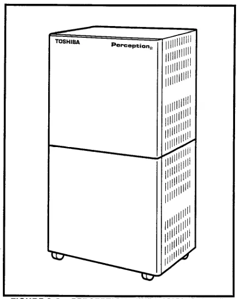
The basic equipment cabinet (NCEC-M) con- sists of a single, free-standing cabinet mounted on casters for easy movement. Once system installa- tion has been completed and the cabinet has been positioned, the casters can be locked to prevent movement. The interior of the cabinet houses two shelves for printed circuit card installation. A sepa- rate area is provided for installation of the power supply and peak load battery. MDF connections are facilitated by amphenol connectors located on the rear of the cabinet (Figure 2-l).FIGURE
2-I-PERCEPTION,
BASIC
CABINET
1 .I0 Expansion Cabinet
1 .I 1
The expansion cabinet (NCEC-S) is a single cabinet that mounts on top of the basic cabinet and is secured in place with four bolts. The cabinet houses two shelves for printed circuit card installa- tion. MDF connections are facilitated by amphenol connectors located on the rear of the cabinet (Fig- ure 2-2).1.20 Power Supply
1.21
The Main Power Supply (NPSA-M) consists2.11
The expansion cabinet (LCEC-S) is a single of a single metal chassis. In addition to the power cabinet that houses a single printed circuit cardTOSHISA
Perception,
FIGURE
P-2-PERCEPTION,
EXPAWIUN
LABINt I
supply, this chassis contains the system ring gen- erator and a charger/inverter for Reserve Power. Located on the front of the chassis are a circuit breaker and LED indicator for each power supply output, and an AC power indicator, and the system power switch. The battery switch is also on the front of the NPSA-M.2. PERCEPTIONex
2.00 Basic Equipment Cabinet
2.01 The basic equipment cabinet (LCEC-M) is a single free-standing cabinet mounted on casters for easy movement. The cabinet contains three shelves for printed circuit card installation. A sepa- rate area is provided for power supply and peak load battery installation. MDF connections are fa- cilitated by amphenol connectors located on the rear of the cabinet (Figure 2-3).
INSTALLATION
INSTRUCTIONS
SECTION
200-255-202
FEBRUARY1992
FIGURE
P-3-PERCEPTION, BASIC CABINETshelf. MDF connections are facilitated by amphe-
nol connectors located on the rear of the cabinet
(Figure Z-4). Up to two expansion cabinets may be
added to the PERCEPTlONe, basic equipment
cabinet.
2.20 Power Supply
2.21
The Main Power Supply (LPSA-M) consists
of a single metal chassis which contains the system
ring generator and charger/inver&er
for the Reserve
Power. A circuit breaker switch, LED indicators, AC
power indicator and system power switch are lo-
cated on the front of the chassis. For ease in
installation a handle is located at the top front of the
power supply (Figure 2-5).
3. PEAK LOAD BAl-rERY
3.00 The peak load battery will maintain call proc-
essing for a maximum of two minutes in the event
the PERCEPTlONe or PERCEPTlONe, experi-
ences a power failure. Additionally, when the sys-
tem is under heavy usage the peak load battery will
FIGURE P-4-PERCEP
-.-..-m - - -a---.-..
HtiUHE 24+PtRCtP I IUNeX
avoid power degradation by supplementing the -24 volts, maintaining a constant power level.
4. EXTENDED RESERVE POWER
4.00 The power supply is equipped, as a standard feature, with an internal battery chargemnverter. Full reserve power can be provided for any system by connecting an appropriate, customer-supplied 24-volt battery pack. During normal operation, the power supply chargemnverter will maintain the proper charge in the battery pack. In the event of an AC power failure, switchover to battery power will be automatic. There will be no loss of system operation as a result of power switchover. When AC power is restored, switchback to the power supply will be automatic.
4.01 Battery selection and size will depend on system size and desired reserve operating time. The maximum power consumption of the basic cabinet is 11.5 amps at -24 VDC. For both a basic and expansion cabinet configuration, the maxi- mum will be 19 amps at -24 VDC. The selected batteries must be compatible with the system’s charger float voltage of 27.3 VDC.
SECTION
200-255-202
FEBRUARY1992
5. POWER FAILURE/EMERGENCY TRANSFER 5.00 The function of the Power Failure/Emergency Transfer Unit (DPFT) is to automatically connect selected trunks to selected standard telephones in the event of system failure while permitting normal operation when the system is in service (maximum of 1 per cabinet).5.01 The DPFT is a self-contained module that mounts externally to the basic cabinet, typically on the MDF. Connections to the trunks, stations and basic cabinet are made via two 50-pin amphenol- type connectors (Jl and J2) on the DPFT (see functional diagram in Figure 2-6).
5.02 The module consists of eight relays that are normally operated, connecting the telephones to NSTU circuits and the trunks to NCOU circuits. If a power failure (or other emergency) occurs, the relays release, connecting the telephones directly to the trunks. Calls can then be placed from the telephones over the CO trunks, bypassing the system (which is out of service).
5.03 Power Fail Transfer (PFT) telephones con-
I J2 NCOU
CO LINE I I
TELEPHONE TELEPHONE
Notes: 1. One of eight DPFT circuits. Notes: 1. One of eight DPFT circuits. 2. Conditions of AC power on. 2. Conditions of AC power on.
FIGURE Z-6-DPFT FUNCTIONAL DIAGRAM FIGURE Z-6-DPFT FUNCTIONAL DIAGRAM
INSTALLATION
INSTRUCTIONS
SECTION
200-255-202
FEBRUARY
1992
netted to ground-start trunks must have ground taps (tap buttons) in order to make outgoing calls during power fail transfer conditions.
5.04 A transfer can be caused by a loss of power or triggered manually by either of two buttons, one of which is located on the underside of the atten- dant console and the other on the front of the NPRU PCB. A transfer that is caused by a power failure will be reset automatically when power is restored; a manual transfer must be reset manually.
5.05 When the DPFT is reset after a transfer, existing PFT conversations will be protected. Indi- vidual circuits will be restored only when they become idle.
6. PRINTED CIRCUIT BOARD DESCRIPTION
6.00 Sixteen different types of PCBs are available for use in both PERCEPTION systems (Figures 2- 7 & 2-8). The universal port architecture enables multiple installation of trunk cards. The PERCEPTlONe can support a maximum of 16 trunk cards; 8 in the basic cabinet, and 8 in the expansion cabinet. The PERCEPTIONex can support a maximum of 32 trunk cards; 24 in the basic cabinet, and 8 in each expansion cabinet.NFDU (Floppy Disk Drive Unit)-One
or two persystem: This card houses a 3.5 inch, 1.2 Mbyte disk drive. One disk contains system program and customer data. The second disk stores the Maintenance and Administration programs. (Two NFDUs are required in D.02 and later version software using Remote Maintenance.)
LCCU (Central Control Unit)-One
per system: The LCCU card contains the circuitry which, under the direction of the system program, pro- vides centralized control for the entire system. Additionally, the LCCU performs data transmis- sion and receiving functions between the central control and all peripheral equipment, including:l Station PCBs l Trunk PCBs
0 TTY interface
l SMDR interface
l Lodging/Health Care audit interface
STATION, DATA, TRUNK, DSS, OR OCA CARDS ONLY
STATION, DATA, TRUNK, DSS, OR OCA CARDS ONLY
FIGURE
P-7sPERCEPTION,
PC6 INSTALLATIONl Modem interface
This circuitry consists of a 16-bit 8OC88 main processor, an 8-bit Z-80 secondary processor, and 1 Mbyte of memory.
SECTION
200-255-202
JANUARY1993
w.iu~t Z-I+PERCEPTION,
PCB INSTALLATION
NPRU (Paging and Music-on-hold Unit)-Housesprogram load and initialization control switches and performs several miscellaneous functions (up to two per system):
l Paging interface and control l Music-on-hold interface l UNA control
l Interface for the NRCU
* Attendant Console Functions
l Power Failure/Emergency transfer control
l Digitized voice message for Automatic Wake-
up (optional)
NRCU (Receiver Unit)-Two per NPRU (4 per system maximum): This card provides DTMF receivers, which are required for receiving tone dialing from standard telephone ports (including voice mail ports) and some incoming trunk (DID, TIE and CCSA) types. It also provides the capa- bility for remote access to service. It mounts piggy-back on the NPRU PCB, where there is available space for two NRCUs. Each NRCU provides four DTMF receiver circuits, with a system maximum of 16.
NOTE:
When using the Call Forward-No Answer to Trunk feature, an NRCU MUSTbe installed in the system.
NEKU (Electronic Telephone Unit)-One per eight electronic telephones: Interfaces electronic telephone to the system. It also serves as an attendant console interface. Each attendant con- sole requires one electronic telephone circuit. PERCEPTION,
ATT #O-PCB position LOO circuit #1 ATT #1 -PCB position L15 circuit #l
A maximum of 12 NEKU/NDKU PCBs may be installed in each cabinet (24 NEKU/NDKU PCBs maximum per system).
PERCEPTION,
ATT #O-PCB position UOO circuit #1 AIT #l -PCB position UOl circuit #l
A maximum of 16 NEKU/NDKU PCBs can be installed in the PERCEPTIONex basic cabinet, and eight in each expansion cabinet.
NDKU (Digital Telephone Unit)-A 2B+D archi- tecture is used to interface up to 8 or 16 circuits for the Digital Telephone and Integrated Data Interface Unit (PDIU-DI), Stand-alone Data In- terface Unit (PDIU-DS), or Digital Direct Station Selection Console. Digital telephones and digital DSS consoles cannot be interfaced to the same NDKU PCB. Four configuration options are switch-selectable as follows:
INSTALLATION
INSTRUCTIONS
SECTION
200-255-202
JANUARY
1993
2)
3)
4)
Option 2: Eight digital telephones with integrated Data Interface Unit (PDIU-DI) or Off-hook Call Announce. This position also supports Stand-alone Data Inter- face Units (PDIU-DS).
Option 3: Four digital DSS consoles. In PERCEPTION, COO and CO1 may be used for this option only.
Option 4: Eight digital DSS consoles. NOTE:
When using Option
2 or 4,
the nexthighest
number adjacent card slotcannot
be used. For example: If an NDKU is installed in LO1 or UO 7, the card slot LO2 or UOZ respective/y, must be left vacant.NSTU (Standard Telephone
Unit)-Interfaces eight standard telephones (DTMF or rotary dial) to the system.NDSU (DSS Console Controller
Unit)-Interfaces four DSS consoles to the system. The NDSU is installed in the COO or COI, or any line slot for PERCEPTION,; or in any universal slot for PERCEPTIONex. A maximum of two NDSU PCBs are allowed per system, and both can be installed in the same cabinet.NDCU (Data Control
Unit)-Interfaces eight Digi- tal Data Interface Units (DDIUs) to the system. The NDCU controls data transmission between the DDIU and the cabinet. A maximum of four NDCU PCBs may be installed in each PERCEPTlONe cabinet. In the PERCEPTIONex, four PCBs per shelf can be installed.NMDU (Modem Pooling
Unit)-Interfaces up to four modems and their associated DDIU-MAs. Any of the four DDIU circuits not required by a modem can be used with a standard DDIU (-MA or -MAT). A maximum of four NMDU PCBs may be installed in each PERCEPTlONe cabinet. In the PERCEPTIONex, four PCBscan be installed per shelf.NOTE:
The system maximum of NDCU or NMDU PCBs consists of any combination of the two
PCBs totaling four per cabinet for PERCEPTlONe and four per she/f for PERCEPTION,, .
NCOU (Central Office Trunk Unit)-One
per four CO trunks: Provides the signaling supervisory functions on loop- and ground-start trunks. Inter- faces four CO trunks to the system. These trunks can be incoming, outgoing, or both way CO trunks; WATS trunks, or Foreign Exchange (FX) trunks.NEMU (E & M TIE Trunk Unit)-One
per four E & M TIE trunks: Each TIE trunk can be individually strapped for Type I or II operation with either 2- wire or 4-wire connection.NLSU (DID Trunk Interface
Unit)-One per four DID trunks: Each NLSU connects four Direct Inward Dialing (DID) trunks to the system.NDTU (Tl
Interface)-Maximum of two per sys-tem (one in the main cabinet, one in the expan- sion cabinet): Each NDTU provides a’ maximum of 24 trunk lines. The Digital Trunk printed circuit card enables the PERCEPTIONehex systems to use DSl signaling to connect directly to either Tl span lines which connect to the telco (through a Channel Service Unit), or to a private network.
NOCU (Off-hook Call Announce interface Unit)-
One per eight electronictelephones. Each NOCU provides eight Off-hook Call Announce circuits for up to eight electronic telephones. Each NOCU takes a station PCB location in the cabinet.
HVSUP (Off-hookCall Announce
PCBs)--Install 1 inside the electronic telephone. One unit per electronic telephone is required to receive off- hook call announce.7. SYSTEM INDICATORS AND CONTROLS 7.00 Several system indicators and controls are located on the various PCBs and assemblies. The locations and functions are:
NFDU
l Disk Drive LED-Will light to indicate when
the disk is being accessed.
l PUSH Button-Used to eject the diskette
from the drive. LCCU
MAJ LED-Lights when a MAJOR alarm exists in the system.
MDR LED-Lights when the DTRsignalfrom the SMDR device is not present. An MDR alarm on the attendant console lights simul- taneously if enabled in programming. AUX LED-Lights when the DTR signal from
the MIS system is not present.
TTY switch-Slide switch used to select 300 or 1,200 bps speed for TTY port. This port is used for either programming and mainte- nance and/or the Lodging/Health Care Audit. MDR switch-Slide switch used to select 300 or 1,200 bps speed for the SMDR port. This port is used for SMDR and/or the Lodging/ Health Care Audit.
AUX switch-This switch is used with MIS system. Must be set at 1200 bps.
NTWU
l CLOCK LED-Flashes contjnuously when
the system is functioning as usual. NPRU
l FALT LED-Indicates software-detected
faults concerning MOH or Paging circuits. . BSYLED1&2
#l lights when any page is in progress. #2 indicates when MOH is in use (a call is on hold or camp-on).
l MOH volume control-Adjust, Music-on-hold
volume level.
l LOAD switch-A momentary switch used in
an emergency condition to reload system program and data from disk. All existing calls will be dropped when this switch is pushed.
l INT switch-A momentary switch used in
SECTION
200-255-202
FEBRUARY1992
emergency conditions to reset system logic. All existing calls will be dropped when this switch is pushed.PFT switch-A locking switch used to manu- ally activate a transfer with the DPFT unit. A transfer activated by this switch can only be reset by this switch.
MDM LED-Not currently used.
PFT LED-LED is ON whenever a power fail transfer condition has been manually initi- ated.
NRCU FALT LEDs 1, 2, 3 & 4-Used to indicate software-detected faults or a dis- abled state caused by an input command from the maintenance terminal (TPER Pro- gram). Each LED indicates two of the four circuits on each of the two NRCUs that can mount on the NPRU.
FALT #l = Circuits 1 & 2, NRCU2 1 FALT #2 = Circuits 3 & 4, NRCU2 1 FALT #3 = Circuits 1 & 2, NRCU2 2 FALT #4 = Circuits 3 & 4, NRCU2 2 NCOU/NEMU/NLSU
l FALT LEDs 1 & 2-Indicate software-de-
tected faults or a disabled state caused by an input command from the maintenance termi- nal (TPER Program) or while ports are pro- grammed. Each LED indicates two of the four circuits on the NCOU, NEMU or NLSU:
FALT #l = Circuits 1 & 2 FALT #2 = Circuits 3 & 4
. BSY LEDs 1 w 4-Indicate the busy/idle status of each of the four circuits on the NCOU, NEMU or NLSU. LED is ON when circuit is busy.
NDTU
l FALT LED-Indicates software-detected
faults or a disabled state caused by an input command from the maintenance terminal (TPER Program) or while ports are pro- grammed. LED indicates fault occuring in more than one channel.
l BSY LED-Indicates the busy/idle status of
the 24 channels on the NDTU. LED is ON when more than one channel is busy.
l FALM LED-Indicates NDTU has not
INSTALLATION
INSTRUCTIONS
SECTlON200-255-202
FEBRUARY1992
l MFALM LED-indicates NDTU has not
achieved Frame Synchronization.
l YALM LED-Indicates a Yellow Alarm is
detected by the NDTU.
l BALM LED-Indicates a Blue Alarm is de-
tected by the NDTU.
l Signaling Type Selection Switches S4 w
Sl l-Six-element DIP switches used to se- lect one of four available signaling modes, on a per channel basis, for each of the 24 NDTU channels. Available signaling modes are:
CO (Loop Start) mode CO (Ground Start) mode DID (2-wire signaling) TIE Line mode (4-wire E&M) NEKWNSTWNOCWNDKU
l FALT LEDs 1 & 2-Indicate software-de-
tected faults or a disabled state caused by an input command from the maintenance termi- nal (TPER Program) or while ports are pro- grammed. Each LED indicates four of the eight circuits on the NEKU, NSTU, NOCU, or NDKU:
FALT #l = Circuits 1 w 4 FALT #2 = Circuits 5 w 8 NDSU
l FALT LEDs 1 & 2-Indicate software-de-
tected faults or a disabled state caused by an input command from the maintenance termi- nal (TPER Program) or while ports are pro- grammed. Each LED represents two of the four ports on the NDSU:
FALT #1 = Circuits 1 & 2 FALT #2 = Circuits 3 & 4 NDCU
l FALT LEDs 1 & 2-Indicate software-de-
tected faults or a disabled state caused by an input command from the maintenance termi- nal (TPER Program) and while ports are programmed. Each LED indicates four of the eight circuits on the NDCU:
FALT #l = Circuits 1 w 4 FALT #2 = Circuits 5 m 8
l NOT READY LEDs DIU l* 4and DIU 5 u 8-
Indicate the DDIU’s (-MA or -MAT) power switch is not in the ON position or tip and ring line polarity is reversed.
NMDU
l FALT LEDs 1 & 2-Indicate software-de-
tected faults or a disabled state caused by an input command from the maintenance termi- nal (TPER Program) and while ports are programmed:
FALT #l = DIU Circuits 1 w 4 FALT #2 = Modem Circuits 1 w 4
l NOT READY LEDs DIU 1 w 4-Indicate the
DDIU’s (-MA or -MAT) power switch is not in the ON position or tip and ring line polarity is reversed.
l BSY LEDs (Modem) 1 Y 4-Indicate the
busy/idle status of each of the four modem circuits (the LED is ON when the circuit is busy).
NPSA-M/LPSA-M
l LEDs indicate the presence of: Ringer and
-48, -24, -12, +12, -5, +5 voltages.
l AC Power LED-Indicates the presence of
AC power to the NPSA-M. NPSA-S
l LEDs indicate the presence of: -48 and -24
voltages.
8. PERIPHERAL EQUIPMENT
8.00 Electronic and Digital Telephone
8.01 Four different electronic telephones and two different digital telephones may be used in the system.
8.02 All electronic telephones share the same dimensions:
Height: 3.7 in. (94mm) Width: 7.1 in. (180mm) Depth: 9.5 in. (241 mm)
8.03 All digital telephones share the same dimen- sions:
Height: 3.6 in. (92mm) Width: 7.3 in. (184mm) Depth: 9.0 in. (229mm)
line cords. Digital telephones are connected to the system via 2-conductor modular line cords. In ad- dition, all models may be used at any or all stations.
8.10 Headset Upgrade (HHEU)
8.11
Each electronic/digital telephone may also be upgraded to provide a modular headset jack by installing a headset upgrade assembly. The as- sembly consists of a small PCB (HHEU) which installs on the main PCB, inside the electronic or digital telephone, with a plug-in connector. Most standard headsets are compatible with the HHEU jack.8.20 Attendant Console
8.21
The Attendant Console is available with face- plates for the Business and Lodging/Health Care applications. The console consists of a plastic housing with handset/headset modular jacks. Two horizontal rows of non-locking buttons, LEDs and a 12-button dialpad enable call processing.8.30 DSS Console
8.31
As an option both electronic and digital Direct Station Selection (DSS) consoles can be used with systems that do not require attendant consoles, or require distributed call-handling positions. Two DSS consoles per electronic/digital telephone, up to a system maximum of eight DSS consoles, can be installed.8.40 Standard Telephone
8.41
Standard telephones can be mixed with elec- tronic telephones as required by the user’s applica- tion, Standard telephones can access all telephone features using dial code access.8.50 DDIWPDIU
8.51
There are four types of Digital Data Interface Units(DDIUs/PDIUs), DDIU-MAT, DDIU-MA, PDIU- DI, and PDIU-DS. The DDIU-MAT is a built-in unit that attaches directly to the bottom of a lo- or 20-button electronic telephone (replacing the base). The PDIU-DI is a built-in unit that attaches directly to the bottom of both digital telephones (replacing the base). The DDIU-MA and PDIU-DS are stand- alone units. Each unit is equipped with a femaleSECTlON200-255-202
FEBRUARY1992
RS-232C connector and operation switches. Both the DDIU-MAT and DDIU-MA are equipped with a power supply that connects to the DDlUs via a 6’ cord, and plugs into astandard 117 VAC wall outlet.8.60 Paging Equipment
8.61
A customer-supplied paging amplifier can work in conjunction with the system’s paging inter- face and speaker zone switching to provide a system paging capability.8.70 Music-on-Hold
8.71
A standard interface enables a customer- provided music source to be connected to the system. This music is connected to all calls placed in the hold, camp-on or call waiting condition by a station or the attendant. The same music source can also be used by the Automatic Wake-up fea- ture for wake-up calls.8.80 Universal Night Answer
8.81
Incoming calls, when the system is in night operation, can be programmed to go either to a night answer station or to a Universal Night Answer device such as a bell or loud ringer. Any station user can pick up a UNA call by either pressing a m button on the telephone or by dialing an access code. Up to two UNA zones can be programmed per system, when the system is in tenant service.8.90 Station Message Detail Recording
INSTALLATION
INSTRUCTIONS
SECTION
200-255-203
FEBRUARY
1992
CHAPTER 3
INSTALLATION SITE REQUIREMENTS
1. COMMERCIAL POWER1 .OO The system requires a power source of 100 m 120 VAC, 50/60 Hz. The AC outlet must be dedi- catedto system use, grounded and fused. To avoid accidental power turn-off, it is recommended that an ON/OFF wall switch not be used on this dedi- cated AC circuit.
1 .Ol If reserve power is to be installed, the battery pack requires a well-ventilated location adjacent to the equipment cabinet.
2. ENVIRONMENTAL REQUIREMENTS
2.00 Humidity at the equipment cabinet should be within 20 - 80% (non-condensing), and the tem- perature should be relatively constant within 32 w 104°F (0 w 40°C). Exposure to dust and airborne chemicals should be avoided.
3. EQUIPMENT ROOM RECOMMENDATIONS 3.00 The minimum floor and maintenance space required for installation of each of the two equip- ment cabinets is shown in Figures 3-l and 3-2.
I I
I REAR WALL
t I
4
6” AIR SPACE’THREE SIDES i I
c I
I I
I 1
t 1
Y 17 314” I
I I
I I I lb I I 1
1 1 2” I I
I I I
I I I
I I
TOP VIEW
TOP VIEW I I I I I
I I I
8
8 NCEC202-M UNIT NCEC202-M UNIT I I I
I I I
I
I I I
I
I
I
I c w I I
I
I I
I
I 4
I
I
I
I FRONT WORK SPACE APPROXIMATELY 36” FRONT WORK SPACE APPROXIMATELY 36” ; ; I
I + + I I
I I I
I I I
I
I I I
FIGURE 3-I-PERCEPTION, MINIMUM FLOOR SPACE
l Stand-alone DDIU-MA/PDIU-DS - 3, 280 cable
feet (1,000 M), 24 AWG
l Attendant Console - 1,000 cable feet (305 M),
24 AWG
3.01 The following requirements must be consid- l Electronic DSS - 500 cable feet, 24 AWG
I
I REAR WALL t
I
I 6” AIR SPACE THREE
f A
22” I
1 2” TOP VIEW
LCEC-M UNIT
I
I FRONT WORK SPACE APPROXIMATELY 36” I
I f
FIGURE 3-P-PERCEPTION, MINIMUM FLOOR SPACE
ered when selecting a location for the equipment cabinet:
The location MUST BE:
l Dry and clean. l Well ventilated. l Well lit.
l Easily accessible.
The location MUST NOT BE:
l Subject to extreme heat or cold. l Subject to corrosive fumes.
l Next to a reproducing or copying ma-
chine.
4. CABLING CONSIDERATIONS
4.00 The equipment cabinet must be located close to the facility Main Distribution Frame (MDF). Maxi- mum house cable run distances for station and peripheral equipment must also be considered when choosing the location of the equipment cabi- net. The limit for each type of equipment is:
l Electronic/Digital Telephone - 1,000 cable feet
(305 M), 24 AWG
l Standard Telephone - 500-ohms (including tele-
SECTION
200-255-203
FEBRUARY
1992
l
Digital DSS - 1,000 cable feet (305 M), 24 AWG
4.01 Acceptable cable for all telephones is 22 or 24
AWG twisted pair inside telephone station cable
(jacketed but not shielded). Two twisted pairs are
required for the electronic telephone, one pair for a
standard telephone, and one twisted pair for the
digital telephone, even if equipped with a PDIU-DI.
Three twisted pairs are required for an electronic
telephone equipped with a DDIU-MAT. The stand-
alone DDIU-MA/PDIU-DS requires one twisted
pair.
4.02 A 25-pair cable is required for the attendant
console. The console is equipped with a male 50-
pin amphenol-type connector.
WARNING!
1. Never install telephone wiring during a
lightning storm.
2.
Neverinstall telephone jacks in wet
locations, unless the jacks are specifi-
cally designed for wet locations.
3. Never touch uninsulated telephone
wires or terminals unless the telephone
line has been disconnected at the in-
terface.
4. Use caution when installing or modi-
fying telephone lines.
5. GROUNDING
5.00 The following grounding directions are re-
quired in order to comply with the Underwriters’
Laboratories’
Standard 1459 2nd edition:
1) Redundant and independent equipment
grounding conductors are to be installed be-
tween the product and the wiring system
ground.
2) One of the equipment grounding conductors
(ground 1) shall be an insulated grounding
conductor. Its size shall not be smaller than
the size of the grounded and ungrounded
branch-circuit supply conductors. It shall also
have their equivalent insulation material and
thickness, except that it is green with, or
wilthout, one or more yellow stripes. This
GROUND 1; THIRD WIRE GROUND TO AC POWER CORD
Perception 3EDICATED
4C OUTLET NITH THIRD NIRE GROUND
-0 GROUND
;YSTEM GROUND
EXTERNAL GROUND SCREW ON PERCEPTION CABINET GROUND 2; PER GENERAL RULES
OF ARTICLE 250 OF THE NATIONAL
ELECTRICAL CODE, NFPA70
FIGURE
3-3-UL GROUNDING
DIAGRAM
insulated grounding conductor is to be in-
stalled as part of the circuit that supplies the
system, and it is to be connected to ground at
the service equipment.
CHAPTER 4
SYSTEM INSTALLATION
1. PERCEPTION,
1 .OO
Power Supply installation1 .Ol Install the main power supply as follows: -
INSTALLATION
INSTRUCTIONS
SECTION
200-255-204
FEBRUARY
1992
6) Check the 15amp fuse (Fl) located at the top of the power supply to verify that it is in working order.7) Remove plastic cover from AC connection terminal TBl by removing two screws. 8) Connect the white and black leads to the AC
terminal (black to L and white to N) and the green lead (ground) to the GND screw on the main power supply (Figure 4-2). Replace the plastic cover and secure with two screws. 1) Remove the two screws securing the basic
cabinet front cover. Lift the cover off the cabinet. 2) Loosen two screws, remove and retain four screws securing the basic cabinet rear cover plate, and remove the rear cover plate (Figure 4-l).
Ir
0\
/f
LOOSEN 2 SCREWS
- REMOVE 4 SCREWS -)(
FIGURE
4-l-PERCEPTION@
BASIC
CABINET
REAR
COVER
3) Unpack the main power supply and inspect it carefully for any visible damage. Verify that all connectors are securely attached.
4) Remove and retain the three corner screws from the back of the main power supply. 5) Slide the main power supply into the basic
cabinet from the front and secure in place with three screws at the rear.
5515 - J509
i- GROUND STRAP
SECTION
200-255-204
FEBRUARY1992
9) With the main power supply turned OFF, plug
the AC power cord into the AC outlet.
10) Momentarily press each circuit breaker to
verify that it is not tripped.
11) Place the main power supply power switch in
the ON position.
WARNING!
Hazardous voltage that may cause death
or injury is exposed at the power supply
AC terminal.
12) Verify that all main power supply power indi-
cator LEDs are on (RINGER LED should be
pulsating rapidly). If any of the LEDs are
noton, replace the main power supply.
13) Using a multimeter (set to the appropriate
ranges), check the pins on connectors 5201,
J202,5203 and J703 for the voltages shown
in Figure 4-3. (The connectors are on the rear
of the power supply chassis.) Measure be-
tween the voltage pin and a ground pin, (Ail
ground leads are tied to a single point, so any
can be used.) Figure 4-3 also shows the
acceptable range for each output voltage. If a
measured voltage falls outside of the accept-
able range, replace the main power supply.
14) Turn the power supply OFF and then connect
J201, J202 and J203, respectively, as shown
in Figure 4-2.
15) Remove and retain the two screws securing
the peak load battery mounting bracket and
slide the bracket out the front of the basic
cabinet.
16) Install the peak load battery as shown in
Figure 4-4. Secure the battery to the mounting
bracket with the retaining strap and a single
screw.
WARNING!
Hazardous voltage that may cause death
or injury is exposed at the peak load bat-
tery cables. DO NOT touch wires together.
17) Connect the peak load battery cables to TB2
on the rear of the basic power supply (see
Figure 4-2). Ensure that the correct polarity is
observed as follows:
blue to positive (+)
yellow to negative (-)
EXPANSION CABINET
$fi; RN;lic] rG1
BASIC CABINET
J201 J202
SIG2 q q SIG 1
RNG CK 0
D
-48V q El G
J703 J203
FPSA ACCEPTABLE
VOLTAGE RANGES
NOMINAL (VDC)
RANGE (VDC)
-48
-47.52 ..a
-48.96
-24
-26.75 - -28.12
+12
+11.76 - +12.48
-12
-11.76 - -12.48
+5
+5.0 - +5.4
-5
-5.0 - -5.4
INSTALLATION
INSTRUCTIONS
SECTION
200-255-204
FEBRUARY1992
FIGURE
4-4-PEAK LOAD
BATTERY
18) Slide the mounting bracket/battery assemblyin place and secure with two screws.
19)
Set theBATTERY BACKUP
switch to ON (Figure 4-5).1.10 Expansion Cabinet Installation
WARNING!Hazardous voltage that may cause death or injury is present in the system during operation. Ensure that AC power to both cabinets is turned off prior to performing this procedure.
NOTE:
A 13mm socket wrench and extension is rec- ommended for ease of expansion cabinet ins talla tion.
1) Remove and retain the four screws securing the basic cabinet top cover and lift the cover off the cabinet (Figure 4-6).
2) Remove and retain the two screws securing each of the expansion cabinet side panels. Pull the side panels off.
3) Place the four casters on the basic cabinet in the lock position to ensure cabinet stability during the expansion cabinet installation. 4) On both the basic and expansion cabinets,
remove and retain two screws securing the cabinet doors. Remove and retain the six screws securing the rear panel on each cabi- net.
L
NPSA2-M
ON
El EiEF
OFF
-48” 0 RINGER 0
AC POWER
0
POWER ON OFF
FIGURE
4-5-PERCEPTION,
POWER
SUPPLY
CONTROLS
AND INDICATORS
d
SECTION
200-255-204
FEBRUARY
1992
5)
6)7)
8)9)
10)
Place the expansion cabinet on top of the
basic cabinet, ensuring proper alignment of
the four mounting holes. Secure in place with
four metric bolts, flat washers and lockwash-
ers.
Reinstall the two side covers on the expansion
cabinet and secure in place using four screws
(two per side).
Install the top cover on the expansion cabinet
and secure with four screws.
Connect the intercabinet
ground wire in accor-
dance with Figure 4-2.
Route the expansion cabinet ribbon cable
from J402 in the expansion cabinet through
the opening provided in the cabinet bottom
and connect to the basic cabinet backplane at
J401.Remove three screws from the secondary
power supply. From the front of the expansion
cabinet slide the power supply into the rack
and secure in place with the three rear screws.
NOTE:Prior to routing intercabinet cabling, check the 15-amp fuse (F2) located at the top of the main power supply to verify that it is in working order,
11)
12)13)
14)
15)
16)Route the power supply cabling through the
hole in the expansion cabinet and connect
both power supplies at the
Pl, P2and P3
receptacles.
With the main power supply turned OFF, plug
the AC power cord into the AC outlet.
Momentarily press each secondary power
supply circuit breaker to verify that it is not
tripped.
Place the main power supply power switch in
the ON position.
Verify that all secondary power supply power
indicator LEDs are on. If any of the LEDs are
not on, replace the NPSA-S
(RINGERLED
should be pulsating rapidly).
Using a multimeter (set to the appropriate
ranges), check the pins on connectors
J70117)
‘8)
19)
20)
and J702 on the secondary power supply for
the voltages shown in Figure 4-3. (The con-
nectors are on the rear of the power supply
chassis.) Measure between the voltage pin
and a ground pin. (All ground leads are tied to
a single point, so any can be used.) Figure 4-
3 also shows the acceptable range for each
output voltage. If a measured voltage falls
outside of the acceptable range, replace the
secondary power supply.
Turn the power supply
OFF.Plug in connectors
J701and J702.
Route cable J703 into the basic cabinet and
plug it into connector J703.
Reinstall the rear panels and doors on both
cabinets and secure in place with screws.
2. PERCEPTION,2.00 Power Supply Installation 2.01 1) 2)
3)
4)
5)
6)7)
8)Install the main power supply as follows:
Remove the two screws securing the basic
cabinet front cover. Lift the cover off the cabi-
net.
Remove and retain six screws securing the
basic cabinet rear cover plate and remove the
rear cover plate (Figure 4-7).
Unpack the main power supply and inspect it
carefully for any visible damage. Verify that all
connectors are securely attached.
Remove and retain the three corner screws
from the back of the main power supply.
Slide the main power supply into the basic
cabinet from the front and secure in place with
three screws at the rear.
Check the two 30-amp fuses (Fl and F2)
located at the top of the power supply to verify
that they are in working order.
-
0
6
L
J30 B J29 !Qi--
J28 !Ob
J27 -1
J26 M
J25 w
J24 -1
J23 -1
J22 m J21 D
J20 -“;101
J,CJ w
Jf,,? w-;-
J511 I- J510~
J509 !op_
J508 I-
J507 !Q,- J506 !Q’;- J505 R J504 D J503 [n J502 FZZ%l J501 EZSI
J524 ID J523 m J522 -1 ~521 B
J520 -1
J519 -1 J516 loi-- J517 a J516 !opI J515 ETBl J514 !Qb J513 IZTZij
h
0
6
L
//
0
e
k.
J30 w J29 [@ZZSl
J’&3 w
J27 -1 J26 -1 J25 -1 J24 W J23 !81
J22 !()b
J21 n J20 D J19 k?iEZZd
J16 w J6l!jEsa J17w J5 1-1
Jl6IpEzzq J4 L-1 J15iGZZSj
J14lZSS%l Jl3m J17m1 Jil n JlO 1-1 J9 !Orl Jt3 m J7 E===Zd
SECTION
200-255-204
FEBRUARY
1992
12) Verify that all main power supply power indi- cator LEDs are on
(RINGER
LED should be pulsating rapidly). If any of the LEDs are not on, replace the main power supply.13) Using a multimeter (set to the appropriate ranges), check the pins on connectors J201, J202, J203, J703 and J803 for the voltages shown in Figure 4-9. (The connectors are on the rear of the power supply chassis.) Meas- ure between the voltage pin and a ground pin. (All ground leads are tied to a single point, so any can be used.) Figure 4-9 also shows the acceptable range for each output voltage. If a measured voltage falls outside of the accept- able range, replace the main power supply. 14) Turn the power supply
OFF
and then connectJ201, J202 and J203, respectively, as shown in Figure 4-9.
15) Remove and retain the two screws securing the peak load battery mounting bracket and slide the bracket out the front of the basic cabinet.
16) Install the peak load battery as shown in Figure 4-4. Secure the battery to the mounting bracket with the retaining strap and a single screw.
WARNING!
Hazardous voltage that may cause death
or injury is exposed at the peak load bat-
tery cables. DO NOT touch wires together.
17) Connect the peak load battery cables to TB2on the rear of the basic power supply (see Figure 4-4). Ensure that the correct polarity is observed as follows:
blue to positive (+) yellow to negative (-)
18) Slide the mounting bracket/battery assembly in place and secure with two screws.
19) Set the BATTERY BACKUP switch to
OFF
Figure 4-l 0.2.10 First Expansion Cabinet Installation
WA RNlNG!
Hazardous voltage that may cause death
or injury is present in the system during
EXPANSION CABINET
5701 5702
$i# RN;;i?$Gi
EXPANSION CABINET
J701 J702
$$ RNfj?$$ zG1
BASIC CABINET
J201 J202
G q U G RNGCK q El SIG1
G q q SIG 2
D
G q q SIG 1 -48V q q SIG 2 -48V q q G
J803
-5V q 0 G -5v q
J203 D
+5V 0 17 G +5V q q G
2; : : 2 +5V q q G +5V q q G +5v q q
D
J703
+5V q q G +5V q q G -5V q q G -5V q q G
FPSA ACCEPTABLE VOLTAGE RANGES NOMINAL (VDC) RANGE (VDC)
-48 -47.52 - -48.96
-24 -26.75 - -28.12
+12 +l 1.76 - +12.48 -12 -11.76 - -12.48
+5 +5.0 - +5.4
-5 -5.0 - -5.4
-48” 0 RINGER 0
I 1
ON El
BA-ITERY BACK UP OFF
-48” 0 RINGER 0
+5v-0-0
-0-o AC POWER
FIGURE4-lo-PERCEPTION,,
POWERSUPPLYCONTROLSANDINDICATORS
INSTALLATiONlNSTRUCTlONS
SECTION
200-255-204
FEBRUARY1992
operation. Ensure that AC power to both
cabinets is turned off prior to performing
this procedure.
NOTE:
A 13mm socket wrench and extension is rec- ommended for ease of expansion cabinet installation. Two expansion cabinets can be installed.
1) Remove and retain the four screws securing the basic cabinet top cover and lift the cover off the cabinet (Figure 4-l 1).
2) Remove and retain the two screws securing each of the expansion cabinet side panels. Pull the side panels off.
3) Place the four casters on the basic cabinet in the lock position to ensure cabinet stability during the expansion cabinet installation. 4) On both the basic and expansion cabinets,
remove and retain two screws securing the cabinets doors. Remove and retain the six screws securing the rear panel on each cabi- net.
5) Place the expansion cabinet on top of the basic cabinet, ensuring proper alignment of the four mounting holes. Secure in place with four metric bolts, flat washers and lockwash- ers.
6) Reinstall the two side covers on the expansion cabinet and secure in place using four screws (two per side).
7) Install the top cover on the expansion cabinet and secure with four screws.
8) Connect the intercabinet ground wire in accor- dance with Figure 4-8.
9) Route the expansion cabinet ribbon cable from J405 in the expansion cabinet through the opening provided in the cabinet bottom and connect to the basic cabinet backplane at
5402.
SECTION
200-255-204
FEBRUARY
1992
FIGURE
4-ll-PERCEPTION,
EXPANSION
CABINET
INSTALLATION
NOTE:
Prior to routing intercabinet cabling, check the
15amp fuse (F2) located at the top of the main
power supply to verify that it is in working
order.
11) Route the power supply cabling through the
hole in the expansion cabinet and connect
both power supplies to the lower connectors
at the Pl , P2 and P3 receptacles.
12) With the main power supply turned OFF, plug
the AC power cord into the AC outlet.
13) Momentarily press each secondary power
supply circuit breaker to verify that it is not
tripped.
14) Place the main power supply power switch in
the ON position.
15) Verify that all secondary power supply power
indicator LEDs are on. If any of the LEDs are
not on, replace the NPSA-S (RINGER LED
should be pulsating rapidly).
16) Using a multimeter (set to the appropriate
ranges), check the pins on connectors 5701
and 5702 on the secondary power supply for
the voltages shown in Figure 4-9. (The con-
nectors are on the rear of the power supply
chassis.) Measure between the voltage pin
and a ground pin. (All ground leads are tied to
a single point, so any can be used.) Figure 4-
9 also shows the acceptable range for each
output voltage. If a measured voltage falls
outside of the acceptable range, replace the
secondary power supply.
17) Turn the power supply OFF.
18) Plug in connectors J701 and J702.
19) Route cable J703 into the basic cabinet and
plug it into connector 5703.
20) Reinstall the rear panels and doors on both
cabinets and secure in place with screws.
2.20 Second Expansion Cabinet Installation
WARNING!
Hazardous voltage that may cause death
or injury is present in the system during
operation. Ensure that AC power to both
cabinets is turned off prior to performing
this procedure.
NOTE:
1)
2) 3) 4) 5) 6) 7) 8) 9) 10)installation. Two expansion cabinets can be installed.
Remove and retain the four screws securing the basic cabinet top cover and lift the cover off the cabinet (Figure 4-l 1).
Remove and retain the two screws securing each of the expansion cabinet side panels. Pull the side panels off.
Place the four casters on the basic cabinet in the lock position to ensure cabinet stability during the expansion cabinet installation. On both the basic and expansion cabinets, remove and retain two screws securing the cabinets’ doors. Remove and retain the six screws securing the rear panel on each cabi- net.
Place the expansion cabinet on top of the basic cabinet, ensuring proper alignment of the four mounting holes. Secure in place with four metric bolts, flat washers and lockwash- ers.
Reinstall the two side covers on the expansion cabinet and secure in place using four screws (two per side).
Install the top cover on the expansion cabinet and secure with four screws.
Connect the intercabinet ground wire in accor- dance with Figure 4-8.
Route the expansion cabinet ribbon cable from J406 in the expansion cabinet through the opening provided in the cabinet bottom and connect to the basic cabinet backplane at J403.
Remove three screws from the secondary power supply. From the front of the expansion cabinet, slide the power supply into the rack and secure in place with the three rear screws. NOTE:
Prior to routing intercabinet cabling, check the 15-amp fuse (F2) located at the top of the main power supply to verify that it is in working order.
11)
12) 13) 14) 15) 16)17)
18)
19)
20)
INSTALLATION
INSTRUCTIONS
SECTION
200-255-204
JUNE1992
Route the power supply cabling through the hole in the expansion cabinet and connect both power supplies to the upper connectors at the Pl, P2 and P3 receptacles.With the main power supply turned OFF, plug the AC power cord into the AC outlet.
Momentarily press each secondary power supply circuit breaker to verify that it is not tripped.
Place the main power supply power switch in the ON position.
Verify that all secondary power supply power indicator LEDs are on. If any of the LEDs are not on, replace the NPSA-S (RINGER LED should be pulsating rapidly).
Using a multimeter (set to the appropriate ranges), check the pins on connectors 5701 and J702 on the secondary power supply for the voltages shown in Figure 4-9. (The con- nectors are on the rear of the power supply chassis.) Measure between the voltage pin and a ground pin. (All ground leads are tied to a single point, so any can be used.) Figure 4- 9 also shows the acceptable range for each output voltage. If a measured voltage falls outside of the acceptable range, replace the secondary power supply.
Turn the power supply OFF. Plug in connectors J701 and J702.
Route cable J703 into the basic cabinet and plug it into connector J803.
Reinstall the rear panels and doors on both cabinets and secure in place with screws. 3. PRINTED CIRCUIT BOARD INSTALLATION 3.00 NFDU
SECTION
200-255-204
JUNE1992
SHIPPING SETTING DEFAULT FDDO SLOT NUMBER: FDDO
o FG
INSTALLER SElTlNG FDDl
SLOT NUMBER FFDI
NEC (FD-235GF-121-U)
SHIPPING SElTlNG IEFAULT FDDO SLOT NUMBER: FDDO
NSTALLER SETTING =DDl
SLOT NUMBER FFDl
D2 D3 m
jHlPPlNG SETTING IEFAULT FDDO iLOT NUMBER: FDDC
FG ISG
D E D C B A
1234 1
USTALLER SElTlNG ‘DDl
#LOT NUMBER FFDl
FG EIG
D E D C B A
123 4
FDD
TEAC (FD-235GF-3121-U)
FIGURE 4-12-NFDU STRAPPING
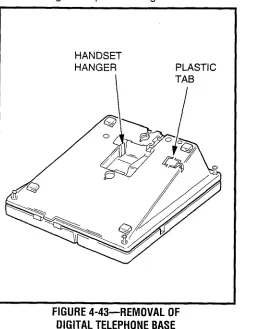
PCB is installed or the type of NFDU that you are working with. Check the identification number on the NFDU and refer to the corresponding diagrams in Figure 4-l 2 which show how the jumper block on the rear of the NFDU must be set.
3.10 LCCU
3.11 Install the LCCU in the CCU slot of the basic cabinet. There are no straps on this PCB; however, there is a plug (P5). Verify that the connection plug is in place in accordance with Figure 4-13.
FIGURE 4-13-LCCU STRAPPING 3.20 NTWU
3.21 The NTWU has one strap that must be veri- fied before installation (Figure 4-14). Install the NTWU in the TWU slot of the basic cabinet. Ensure that the strap is as follows:
TBC5: pins 1 & 2 must be strapped 3.30 NPRU
3.31 The NPRU has one strap that requires verifi- cation before installation (Figure 4-15). If Auto- matic Wake-up is required, verify that the DROM is installed in the IC15 socket. Install the NPRU in the PO0 slot. (An NPRU must be installed in the PO0 card slot.) If a second NPRU PCB is used, install it in the PO1 slot in the PERCEPTION, expansion cabinet. In PERCEPTlONe,, both NPRUs are in- stalled in the basic cabinet. Verify that TBl is strapped as follows:
INSTALLATION
INSTRUCTIONS
SECTION
200-255-204
JUNE1992
-Tl
0NTWU3
FIGURE 4-14-NTWU STRAPPING NOTE:
DROM on/y required for digitized voice on automated wake-up calls.
3.32 If NRCUs are to be installed, mount them on the NPRU. The first NRCU mounts on connector J3, the second on J4 (see Figure 4-16).
3.40 NEKU, NDKU, and NOCU
3.41 Install the NEKU in any of the line designated slots LOO N Lll or L15 m L26 in PERCEPTlONe. If an attendant console is used, an NEKU must be installed in slot LOO. If a second attendant console is installed, a second NEKU must be installed in slot L15. Attendant consoles must be installed on cir- cuit 1 in both slots.
FIGURE 4-15-NPRU STRAPPING
FIGURE 4-16-NRCU MOUNTING
3.42 For PERCEPTlONe,, install the NEKU in any designated slot UOO N U31. To utilize attendant consoles, install NEKUs in the following slots:
AlT#O-PCB position UOO Circuit #l ATT#l -PCB position UOl Circuit #l
3.43 There are no straps on the NEKU PCB for either system.
3.44 Install the NDKU in any of the line designated slots LOO m Lll orL15 w L26 in PERCEPTlONe. For PERCEPTlONe,, install the NDKU in any des- ignated slots UOO W U31. Some options require adjacent PCB slots be left vacant.
3.45 The NDKU employs a 2B+D architecture for each circuit that must be configured for one of four different operating options using the dip switch Sl (Figure 4-l 7) as follows:
IPTION S-l POSITION OPERATION
1 DIP switches 1 - 4: ON DKT only
DIP switches 2 4: ON -
2 DKT with DIL
DIP switch 1: OFF or OCA
3 DIP switchesl, 3, and 4: ON
DIP switch 2: OFF 4 DSS only
I
1
I
4 DIP switches 1 and 2:OFF
DIP switches 3 and 4: ON 8 DSS only