The sPHENIX Experiment
Carlos E.Pérez Lara1,, for the sPHENIX Collaboration 1Stony Brook University, Physics and Astronomy Department
Abstract.Our understanding of QCD under extreme conditions has advanced tremen-dously in the last 20 years with the discovery of the Quark Gluon Plasma and its charac-terisation in heavy ion collisions at RHIC and LHC. The sPHENIX detector planned at RHIC is designed to further study the microscopic nature of the QGP through precision measurements of jet, upsilon and open heavy flavor probes over a broad pTrange. The
multi-year sPHENIX physics program will commence in early 2023, using state-of-the art detector technologies to fully exploit the highest RHIC luminosities.
The experiment incorporates the 1.4 T former BaBar solenoid magnet, and will feature high precision tracking and vertexing capabilities, provided by a compact TPC, Si-strip intermediate tracker and MAPS vertex detector. This is complemented by highly granular electromagnetic and hadronic calorimetry with full azimuthal coverage.
In this document I describe the sPHENIX detector design and physics program, with particular emphasis on the comprehensive open heavy flavour program enabled by the experiment’s large coverage, high rate capability and precision vertexing.
1 Introduction
The ultimate exploration of the properties of the hot QCD matter formed in heavy ion collisions requires a complementary study of the observables produced at both RHIC and LHC energies. Since both accelerators collide ions at different center of mass energy, the initial temperature of the QGP
will be different and so will the in-medium evolution of hard probes. The main observables for a full
characterization of the QGP dynamics include: jet and heavy flavor energy loss, since jets and heavy flavor are produced early in the collision and can be used to probe the whole evolution of the system; sequential suppression of quarkonia, since they are sensitive to the temperature of the system; among others.
The sPHENIX detector [2] is a new detector at RHIC that replaces the PHENIX experiment, which concluded its final data taking run in 2016. The detector system has been designed to cope with the challenging physics goals that will be pursued at RHIC during its high intensity era in the 2020s. In these proceedings, I will briefly described the main elements of the current detector design, its performance and the running scenario for a possible five year plan.
2 The sPHENIX Experiment Timeline
Since its formation in 2015, the sPHENIX collaboration has been guiding the experiment realization through different stages. The conceptual detector design was approved in late 2016 and currently the
Table 1.Running scenario in a five-years plan
Year System Weeks Samp. Lum (all Z)
1 Au+Au 16 34 nb−1
2 p+p 11.5 267 pb−1
2 p+Au 11.5 1.46 pb−1
3 Au+Au 23.5 88 nb−1
4 p+p 23.5 783 pb−1
5 Au+Au 23.5 92 nb−1
design for the proposed detector is being finalized. The detector construction is scheduled to begin in late 2018 and its installation at RHIC will start in late 2020. Data taking is envisioned to start in the middle of 2023 which overlaps greatly with LHC Run 3 timeline and may continue past the LHC Long Shutdown 3 (LS3).
sPHENIX will record data during the RHIC’s highest intensity era for three different systems p+p,
p+Au and Au+Au at RHIC’s top energy √sNN=200 GeV . The proposal for a five-year running plan
starts with six weeks of Au+Au the first year followed by 23 weeks of both p+p and p+Au in the next
year. The next three years sPHENIX will be recording Au+Au and p+p events at even much higher
rates. During the five year running plan, summarized in table 1, sPHENIX will record around 240 billion (1.5 trillion) minimum bias events for Au+Au with a collision vertex reconstructed in|Z|<10 cm (all Z). Furthermore the usage of high level triggers in Au+Au collisions for b-tag or photon-tag
events will increase the number of events by about a factor 2.
3 Detector Description
The detector features full azimuthal coverage and a wide pseudorapidity acceptance|η|<1.1 and its final configuration is currently under intense R&D. The central detector consists of a charge particle tracking system provided by three subdetectors with complementary technology and a calorimetry system with both electromagnetic and hadronic components. At the time of this conference the fol-lowing technologies and specifications are part of the detector configuration:
Layer 0 Layer 1 Layer 2 Min. Radius (mm) 22.4 30.1 37.8 Max. Radius (mm) 26.7 34.6 42.1 Sensitive Length (mm) 271 271 271 Active area (cm2) 421 562 702
N. of pixel chips 108 144 180
N. of staves 12 16 20
Table 1.Running scenario in a five-years plan
Year System Weeks Samp. Lum (all Z)
1 Au+Au 16 34 nb−1
2 p+p 11.5 267 pb−1
2 p+Au 11.5 1.46 pb−1
3 Au+Au 23.5 88 nb−1
4 p+p 23.5 783 pb−1
5 Au+Au 23.5 92 nb−1
design for the proposed detector is being finalized. The detector construction is scheduled to begin in late 2018 and its installation at RHIC will start in late 2020. Data taking is envisioned to start in the middle of 2023 which overlaps greatly with LHC Run 3 timeline and may continue past the LHC Long Shutdown 3 (LS3).
sPHENIX will record data during the RHIC’s highest intensity era for three different systems p+p,
p+Au and Au+Au at RHIC’s top energy√sNN=200 GeV . The proposal for a five-year running plan
starts with six weeks of Au+Au the first year followed by 23 weeks of both p+p and p+Au in the next
year. The next three years sPHENIX will be recording Au+Au and p+p events at even much higher
rates. During the five year running plan, summarized in table 1, sPHENIX will record around 240 billion (1.5 trillion) minimum bias events for Au+Au with a collision vertex reconstructed in|Z|<10 cm (all Z). Furthermore the usage of high level triggers in Au+Au collisions for b-tag or photon-tag
events will increase the number of events by about a factor 2.
3 Detector Description
The detector features full azimuthal coverage and a wide pseudorapidity acceptance|η|<1.1 and its final configuration is currently under intense R&D. The central detector consists of a charge particle tracking system provided by three subdetectors with complementary technology and a calorimetry system with both electromagnetic and hadronic components. At the time of this conference the fol-lowing technologies and specifications are part of the detector configuration:
Layer 0 Layer 1 Layer 2 Min. Radius (mm) 22.4 30.1 37.8 Max. Radius (mm) 26.7 34.6 42.1 Sensitive Length (mm) 271 271 271 Active area (cm2) 421 562 702
N. of pixel chips 108 144 180
N. of staves 12 16 20
Figure 1.The MVTX detector consists of three layers of silicon pixel detector (MAPS) located very close to the beam pipe and featuring fast response and accurate position measurements for tracking and vertexing.
Radius Number of Strip Size (cm) Ladders (φ×z, mm)
0 6 20 0.078×18 (18)
1 8 26 0.086×20 (20)
2 10 32 0.086×20 (20) 3 12 38 0.086×20 (20)
Figure 2.The INTT detector has four layers of silicon strip technology situated in between the MVTX and TPC detectors. It aids the pattern recognition and momentum reconstruction for the central tracking system.
3.1 Charged Particle Tracking
The sPHENIX detector is designed around the 1.4 T superconducting solenoid magnet used previously in the BaBar experiment. The magnet is 3.8 m long with an inner radius of 140 cm and a thickness of 33 cm. The charge particle tracking detectors will be housed inside the magnet and is based on three different detector technologies: a silicon pixel detector (MVTX), for accurate measurements of
displaced vertices; a silicon strip detector (INTT), for complementary high momentum resolution, and a compact time projection chamber (TPC) for high resolution up to low transverse momentum (∼0.2 GeV/c).
The MVTX detector consists of three layers of silicon pixel detectors deployed radially as indi-cated in figure 1. The technology is based on that used by the ALICE ITS upgrade program: the MAPS sensors. It features a fine pitch of 28×28µm2 together with good time resolution of 5µs. The detector has a DCA resolution better than 25µm for charged particles with transverse momentum higher than 1 GeV/c.
The INTermediate Tracker (INTT) detector consists of four layers of silicon strip technology used previously in the FVTX detector at PHENIX. The INTT not only improves the momentum resolution for charged particles with the high transverse momentum, but also aids in the pattern recognition and event synchronization. The geometrical configuration of the detector can be seen in figure 2.
Figure 4. A drawing of part of the EMCal detector is shown on the left, where the block segmentation is also displayed. An individual tower and a SiPMT (resistent to hard magnetic field enviroment) is shown in the right.
The compact Time Projection Chamber (TPC) is the main tracking element of the sPHENIX experiment. The TPC field cage spans a volume from 20 cm to 78 cm in radius and 211 cm in longitude. It will run on continuous readout mode using micro pattern gas detectors at the end plates. The readout will be segmented into 72 modules: 2×12×3 (Z×φ×R) using both rectangular and zigzag pad geometries. The TPC will use a Ne-based gas for high ion mobility and low transverse diffusion in order to minimize spatial distortions from space charge build-up without compromising
the desired position resolution. Its geometrical configuration is detailed in figure 3.
3.2 Calorimetry Detectors
The ElectroMagnetic Calorimeter (EMCal), figure 4, is the innermost calorimeter and consists of absorber blocks made from tungsten powder with embedded scintillating fibers. The design is similar to the SPACAL configuration used successfully in the past by various experiments. It features a sampling fraction of 2.3% and highly granular segmentation∆η×∆φ=0.024×0.024 (approx. 25k readout channels) while providing an energy resolution better than 15%/√E.
The Hadronic Calorimeter (HCal), figure 5, consists of steel and scintillating tiles with wavelength shifter fibers. The HCal system will have two subdetectors: one installed in between the EMCal and
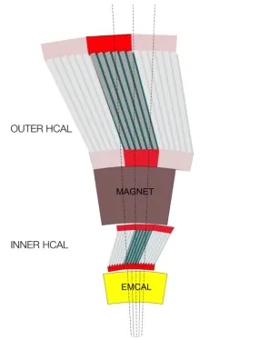
Figure 5.Traverse view of one sector of the hadronic calorimeter system (both inner and outer) together with the EMCal for scale comparison. The steel part of the HCal is also used as a return yoke for magnetic field containment. The geometrical orientation of the wavelength fibers is oposite between the inner and outter
Figure 4. A drawing of part of the EMCal detector is shown on the left, where the block segmentation is also displayed. An individual tower and a SiPMT (resistent to hard magnetic field enviroment) is shown in the right.
The compact Time Projection Chamber (TPC) is the main tracking element of the sPHENIX experiment. The TPC field cage spans a volume from 20 cm to 78 cm in radius and 211 cm in longitude. It will run on continuous readout mode using micro pattern gas detectors at the end plates. The readout will be segmented into 72 modules: 2×12×3 (Z×φ×R) using both rectangular and zigzag pad geometries. The TPC will use a Ne-based gas for high ion mobility and low transverse diffusion in order to minimize spatial distortions from space charge build-up without compromising
the desired position resolution. Its geometrical configuration is detailed in figure 3.
3.2 Calorimetry Detectors
The ElectroMagnetic Calorimeter (EMCal), figure 4, is the innermost calorimeter and consists of absorber blocks made from tungsten powder with embedded scintillating fibers. The design is similar to the SPACAL configuration used successfully in the past by various experiments. It features a sampling fraction of 2.3% and highly granular segmentation∆η×∆φ=0.024×0.024 (approx. 25k readout channels) while providing an energy resolution better than 15%/√E.
The Hadronic Calorimeter (HCal), figure 5, consists of steel and scintillating tiles with wavelength shifter fibers. The HCal system will have two subdetectors: one installed in between the EMCal and
Figure 5.Traverse view of one sector of the hadronic calorimeter system (both inner and outer) together with the EMCal for scale comparison. The steel part of the HCal is also used as a return yoke for magnetic field containment. The geometrical orientation of the wavelength fibers is oposite between the inner and outter
calorimeters.
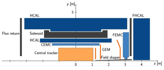
Figure 6.Sided-view drawing of the sPHENIX detector including the proposal for an upgrade in the forward p-going direction. The forward subsystem features a GEM tracker and both electromagnetic and hadronic calorime-ters.
the magnet (inner HCal) and one installed outside of the magnet (outer HCal). The later will be used also as a return yoke for the magnetic field. The inner (outer) HCal thickness amounts to 1.0 (3.5) interaction lengthsλI. Both subdetectors feature a granular segmentation of∆η×∆φ=0.1×0.1.
Both calorimeter systems were designed to have full azimuth coverage and complement each other in the reconstruction of jets. The performance of the calorimeter prototype has recently been assessed at a testbeam in Fermilab and the results of this study can be found in [3].
3.3 Detector Upgrade in the Forward Region
The sPHENIX collaboration has also prepared a comprehensive detector upgrade in the forward ra-pidity region [4]. The forward detector, see figure 6, consists of a forward tracker and calorimetry stations with a pseudorapidity coverage of−1 < η < 4. The forward upgrade allows for a broad physics program. It will not only allow for the study of nuclear structure and production at low X, but also complement the phase space of the sPHENIX central barrel in the pursue of photon-hadron correlations with a wide rapidity gap.
4 Simulation of Combined Performance
The sPHENIX collaboration has been working to put together a comprehensive software framework for the detector description and the different analyses being performed. There are many different
topics studied in the different working groups in the collaboration. The following paragraphs are brief
descriptions of a couple of selected topics.
4.1 Suppresion of b-jets
Figure 7.Left: b-jet RAAas a function of transverse momentum for most central Au+Au collisions at √s=200
GeV. The data sample consists of 240 billion events which would be the amount recorded based on the five-years run plan where no L1 trigger was used. Right: Efficiency vs purity of the L1 b-jet trigger performance
for HIJING simulation of most central Au+Au collisions using one of the methods being studed in sPHENIX.
Respective plots for other methods/conditions can be found in [5]
virtualities. In sPHENIX, jets produced by b quark showers can be reconstructed down to pT =15 GeV/c which allows for the exploration of the relevant mechanisms for their in-medium energy loss.
Figure 7 shows the accuracy expected in the nuclear modification factor of b-jets for 240 billion most central Au+Au collisions. In order to increase accuracy, specially at high pT, studies of several
L1 trigger algorithms have been performed. One of them requires that tracks from the candidate jet do not originate from the main vertex but are rather displaced. Figure 7 shows the performance of such an algorithm using the sPHENIX tracking system to tag one, two and three tracks with displaced vertex. There is currently work in progress [5] to refine this selection as our tracking system is being
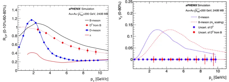
Figure 8.Simulation of the performance of D-meson RCPand v2for MB Au+Au collisions at √s=200 GeV.
Figure 7.Left: b-jet RAAas a function of transverse momentum for most central Au+Au collisions at √s=200
GeV. The data sample consists of 240 billion events which would be the amount recorded based on the five-years run plan where no L1 trigger was used. Right: Efficiency vs purity of the L1 b-jet trigger performance
for HIJING simulation of most central Au+Au collisions using one of the methods being studed in sPHENIX.
Respective plots for other methods/conditions can be found in [5]
virtualities. In sPHENIX, jets produced by b quark showers can be reconstructed down to pT =15 GeV/c which allows for the exploration of the relevant mechanisms for their in-medium energy loss.
Figure 7 shows the accuracy expected in the nuclear modification factor of b-jets for 240 billion most central Au+Au collisions. In order to increase accuracy, specially at high pT, studies of several
L1 trigger algorithms have been performed. One of them requires that tracks from the candidate jet do not originate from the main vertex but are rather displaced. Figure 7 shows the performance of such an algorithm using the sPHENIX tracking system to tag one, two and three tracks with displaced vertex. There is currently work in progress [5] to refine this selection as our tracking system is being
Figure 8. Simulation of the performance of D-meson RCPand v2for MB Au+Au collisions at √s=200 GeV.
The sample corresponds to 240 billion Hijing Events, which amounts to the expected statistics collected during the full experiment lifetime.
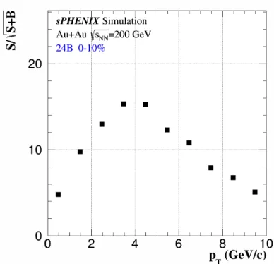
Figure 9.Significance of fully reconstructed B+
mesons as a function of transverse momentum for 240 billion most central Au+Au collisions at √s=200
GeV. The peak at 4 GeV/c is due to the large
combinatorial background present for low pT
candidates.
finalized, however one can see in this plot the rough interplay of efficiency and purity depending on
the severity of the cut used for triggering.
4.2 Fully reconstructed open heavy flavor
The dynamics of the parton energy loss in the QGP can be addressed via the study of suppression and angular correlations of fully reconstructed charm and bottom mesons. These measurements are possible due to the high spatial resolution of the MVTX for reconstruction of displaced vertices and the high momentum resolution for charged particles down to low pTprovided by the TPC and INTT detectors. The decay channel explored is the decay of open charm (one decay vertex) and bottom (two decay vertexes) into hadrons (i.e. D0 → K−π+and B±→D¯0(Kπ)π±). Figure 8 shows the accuracy estimation for central to peripheral yield ratio in inclusive D-mesons and D0from B using 240 billion MB events. Figure 9 shows the significance of the B+meson fully reconstructed via double decay
vertex for most central Au+Au collisions at √s=200 GeV. For both D- and B-mesons, the selection
is done via topological multivariate cuts. A feature of sPHENIX is its low transverse momentum reach for heavy flavor measurements, which is important since low pT hadrons are most sensitive to the medium as it expands and cools down, i.e. collective flow and heavy flavor transport.
5 Summary
In these proceedings, I have summarized the sPHENIX detector’s current design. R&D project is ongoing in order to finalize the detector layout by 2018. The reader can go to https://www.sphenix.bnl.gov/ for the most up-to-date detector description. The detector
technolo-gies have been chosen to provide a broad acceptance coverage, high momentum resolution down to 0.2 GeV/c for charged particles, highly granular electromagnetic and hadronic calorimetry, and quick
References
[1] A. Aprahamianet al., “Reaching for the horizon: The 2015 long range plan for nuclear science”, INSPIRE-1398831
[2] Adare, A. and others, An Upgrade Proposal from the PHENIX Collaboration, ARXIV:1501.06197
[3] Aidala, C. A. and others, Design and Beam Test Results for the sPHENIX Electromagnetic and Hadronic Calorimeter Prototypes, ARXIV:1704.01461
[4] sPHENIX Forward Instrumentation. sPHENIX analysis note: sPH-cQCD-2017-001
[5] Heavy Flavor Jet Simulation and Analysis. sPHENIX simulation analysis note: sPH-HF-2017-001
[6] D0-meson and B+-meson production in Au+Au Collisions at √s
NN =200 GeV for sPHENIX.