336 |
P a g e
DESIGN AND PERFORMANCE ANALYSIS OF SINGLE
INLET MULTIPLE OUTLET JET NOZZLE WITH
THRUST VECTOR CONTROL
PV Senthiil
1,VS Mirudhuneka
2,
Aakash Shirrushti
3 1Head, Advance Manufacturing Technology, Mechanical Engineering,
St.Peters University, Chennai-600054 (India)
2
SAP Consultant, IBM Ltd, Porur, Chennai (India)
3
Department of Mech, SRM University, Chennai (India)
ABSTRACT
Today, thrust vectoring has become a very important research subject which can dramatically change the way
aircraft maneuver and its performance. This paper tries to present a unique approach to this topic by highlighting a
concept defined as Single Inlet Multiple Outlet (SIMO) in detail. This can be explained by having multiple nozzles
for exhaust purpose than those conventional one or two nozzles as we know of presently. This idea may yet not be
able to apply directly to VTOL (Vertical Takeoff & Landing), but can be applied very well to change thrust direction
of the aircraft effectively including thrust reversal and hence reducing the dependability on the primary control
surface to great extent. These nozzles can be made to work in tandem with primary control surfaces so that, in case
of failure of primary control surfaces occur, the aircraft can still be maneuvered and saved thereby avoiding loss of
millions of dollar worth of property, aircraft and most important pilot’s life.
I INTRODUCTION
In present day aircrafts, power plants constitute the lifeline of the plane and for military aircrafts, power plant has
become more significant since it is the one which provides the aircraft of almost all its performance characteristics.
Nozzle is a very significant part of the aircraft engine and which not only propels the aircraft but now even can assist
the aircraft in performing maneuvers, TVC Nozzles used in JSF-Joint Strike Fighter, USA; Sukhoi 30MKI, India to
name a few. The above stated aircrafts use advanced nozzle technology called THRUST VECTOR CONTROL.
Present day aircrafts currently employ one nozzle per engine. This paper presents a new concept called SIMO
(Single Inlet Multiple Outlet) which employ five nozzles instead of one nozzle to single engine. With four of these
five nozzles equipped with thrust vector control, we can achieve all directional control of the aircraft thus reducing
our dependence on the control surfaces. This paper discusses the following aspects concerned with this concept.
1. Thrust Vectoring
2. SIMO Arrangement
337 |
P a g e
4. Aerodynamic Effects5. Engine Thrust Aspects
6. Loss Analysis
7. Possible Applications
8. Limitations
9. Conclusions
II THRUST VECTORING
Thrust vectoring, also thrust vector control (TVC), is the ability of an aircraft, rocket, or other vehicle to manipulate
the direction of the thrust from its engine(s) or motor in order to control the attitude or angular velocity of the
vehicle.In rocketry and ballistic missiles that fly outside the atmosphere, aerodynamic control surfaces are
ineffective, so thrust vectoring is the primary means of attitude control.In aircrafts, the TVC is used to increase the
rate at which the aircraft perform its maneuvering. Fig.1 shows the aircraft without TVC and Fig.2 shows the effect
of thrust vector control employed in US F-22 Raptor which can vector its thrust up to 20° about its vertical plane.
Fig.1 F-22 without TVC ability Fig.2 F-22 with TVC Ability
In TVC, the nozzle of the aircraft engine is tilted in order to produce a vectored thrust with respect to the center line
of the aircraft. Few aircrafts like MiG-29, F-16 etc use two nozzles to expand the combustion product and both the
nozzles are equipped with TVC.
III SIMO ARRANGEMENT
In general aircraft jet engines have nozzle which have one inlet and one outlet whereas the SIMO nozzle is having
one inlet and five outlets. Fig.3 shows an isometric conceptual model of SIMO.
Fig.3 SIMO Nozzle
It consists of one primary outlet and four secondary outlets. The primary outlet is in the center location of the nozzle
338 |
P a g e
with Thrust Vectoring System. This is done to provide stability to the aircraft as this primary outlet will providesteady thrust in one direction only. This will avoid the aircraft to go into a continuous rolling motion or auto rotation
as rockets and missiles normally undergo during their flight.
The secondary outlets are equipped with thrust vectoring system. The arrangement of the secondary outlets will be
in Diamond Formation around the primary outlet. This secondary outletcluster is in diamond formation rather than
in rectangular formation so as to avoid over heating of secondary outlet walls during the deflection of the secondary
outlets. In rectangular formation, performing yaw and pitching maneuvers will lead exhaust from the two secondary
outlets almost directly heating the other two adjacent secondary outlet walls.
In diamond (rhombus shape) arrangement of the secondary outlet system they are located around the primary outlet
shape in a rhombus formation. During any maneuver, pitching or yawing the exhaust from the any one secondary
outlet will lead to the heating of the outer primary outlet wall whole throughout. Therefore, the cooling of the outer
wall of the primary nozzle wall is of prime importance and will be discussed further later in the paper. The
secondary outlets in horizontal plane will work like elevon control in military aircrafts. That is, both the outlets will
move in same direction and also in different direction.
Fig.4 Rectangular Rhombus
Both the diamond and rectangular arrangement of the secondary nozzle arrangement is shown in the diagrams above.
III MECHANISM
The mechanism for TVC is based on Nozzle Actuation System. The actuation system employs the tilting of the
secondary outlets over their hinged joints at the required angle. The nozzle actuation system is similar to the TVC
nozzle actuation system employed by present day defense aircrafts like the US-JSF (Joint Strike Fighter), Su-30MKI
(Sukhoi 30 variant for Indian Air Force). The outlet tilting angle has to be kept minimum to avoid thrust losses and
nozzle efficiencies due to unparalleled fluid flow in the nozzle with respect to the tilted nozzle axis. This mechanism
requires the fluid flow in the nozzle to be as parallel to the nozzle axis as possible with minimum angle variation
between the two. A typical Nozzle Actuation System is shown in Figure 5.
This SIMO concept can very well be applied to perform any aircraft maneuver. Following are the diagrams
(Fig.6,7,8) which illustrate the movement of secondary nozzles to perform basic aircraft maneuvers i.e. Pitch, Yaw,
339 |
P a g e
Fig.5 Typical 3-D Nozzle Actuation SystemFig.6 shows the pitch motion (nose up and down) of an aircraft is achieved by actuating the two outlets, placed in
horizontal plane, similarly about the same plane. The creation of torque is shown in next figure.
Fig.6 Pitch Motion
Fig.7 shows the yaw motion (nose left and right) which is achieved by actuating the two outlets, placed in vertical
plane, similarly about the same plane.
340 |
P a g e
Fig.8 shows the Roll motion of an aircraft which is achieved by actuating the horizontal plane outlets in differentdirections about the same plane. When one outlet goes up the other goes down.
Fig.8 Roll Motion
IV AERODYNAMIC EFFECTS
The aerodynamic characteristics of the aircraft will not be affected much as the nozzles are perfectly streamlined to
reduce any aerodynamic losses due to drag and other factors.
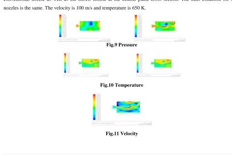
Figure shows the domineand the variations of Static pressure, Temperature and the Total Temperature of the
conventional nozzle as well as the SIMO nozzle at the central plane cross section. The inlet condition for both
nozzles is the same. The velocity is 100 m/s and temperature is 650 K.
Fig.9 Pressure
Fig.10 Temperature
341 |
P a g e
Fig.12 SIMO: Grid & Velocity
Fig.13 Static and Total Pressure
Fig.14 Static and Total Temperature
The outlets are in diamond like arrangement which will prevent the interference of streamline flow due to the
secondary outlets at the outer periphery of the nozzle arrangement. The other aerodynamic aspects of the nozzle will
be same as that of the conventional nozzle systems used in other aircrafts.
4.1 Loss Analysis
The losses will be mainly due to the vectored thrust arrangement. The velocity vector in the direction (in case of
downward component of velocity) the component will be V2*COS α where α being the angle of the vectored thrust
or the angle by which the secondary nozzles will change tilt or shift.
The loss in this case will be V2 – V2COS α
Where,
V1 = Inlet velocity in the nozzle before expansion in the nozzle
V2 = Outlet velocity in the nozzle after expansion in the nozzle.
This loss will be compounded in the form of four secondary nozzles. So the total losses can be found as to be
L = 4 * (V2 – V2 COS α)
This loss can be minimized reducing the angle α by reducing this angle we can control the losses in this nozzle
system. The angle α can be effectively reduced as for an angle we have four corresponding secondary nozzles, each
of which will generate an equal amount of thrust in the required direction.
4.2 Thrust loss
While analyzing the velocity counters for both convergent and SIMO nozzle, it is clear that about 21% of loss
occurs at the exit velocity. That is, a loss of 21% in thrust is occurring while employing the SIMO nozzle instead of
342 |
P a g e
this paper. The fighter aircrafts generally employed with engine with excess thrust therefore this arrangement willnot affect the required thrust.
V ENGINE THRUST ASPECTS
The TVC technique was originally envisaged to provide upward vertical thrust as a means to give aircraft VTOL or
STOL capability. Subsequently it was realized that the use of vectored thrust in combat situations enabled an aircraft
to perform various maneuvers not available to conventional-engine planes. Most currently operational vectored
thrust aircraft use turbofans with rotating nozzles or vanes to deflect the exhaust stream. This method can
successfully deflect thrust through as much as 90 degrees, relative to the aircraft centerline. However, the engine
must be sized for vertical lift, rather than normal flight, which results in a weight penalty. Afterburning (or Plenum
Chamber Burning in the bypass stream) is difficult to incorporate and is not practical for Take-off/Landing, because
the very hot exhaust leaves scorch marks on the ground. Without afterburning it is difficult to reach supersonic flight
speeds. A fluidic nozzle diverts the thrust via fluid effects Given below is a diagram to explain as to how this nozzle
system will help to get change in direction of the aircraft using engine thrust.
As we can see in the diagram shown below, the horizontal velocity component is due to Primary Nozzle and the far
oblique velocity going extreme downward is the Secondary Nozzle velocity component (due to the vectoring of the
upper and two side secondary outlets in the upper direction with the required angularity).
Fig.15 Resultant Motion
As a result, we have a resultant velocity in a direction between these two primary outlet and secondary outlets
velocity components. Hence, we can use the engine thrust to direct the aircraft to the required direction and sense.
To generate max thrust in the downward direction we close all the nozzles except the top one which is vectored
upwards with maximum angularity to give us the maximum thrust in that direction. Similarly we can also generate
maximum thrust in all the four directions by leaving only the corresponding nozzle open and can generate the
required thrust in any direction by working the primary nozzle and secondary nozzle in perfect co-ordination and in
tandem. Hence, above in the diagram we have shown clearly how the aircraft velocity will be in this kind of nozzle
arrangement. The primary outlet velocity will keep changing its direction downwards and the operating nozzle will
also go downwards and hence the resultant velocity will also keep going downwards and hence proper control of the
vectoring nozzle is required to make this nozzle arrangement a very effective tool for increasing aircraft
performance, its maneuverability and its safety.
The primary outlet will account for 40% of the thrust generated by the engine. The rest 60% of the engine thrust is
divided among the secondary outlets with thrust vectoring capability. This 60% of the thrust is divided into 15% in
343 |
P a g e
coming out of the combustion chamber. The thrust to weight ratio of the aircraft installed with this kind of thrustvectoring capability can be adjusted to acceptable range by reducing the wing aspect ratio to a minimum with
reduced dependability on the primary control surfaces. These control surfaces can complement this nozzle system in
performing the necessary maneuvers. This kind of arrangement between the nozzle system and the control surfaces
gives the aircraft an extremely high degree of maneuverability and make it very competitive in air dogfights.
5.1 Cooling
The cooling of the primary outlet due to the vectoring of the secondary outlet is taken care of by having an effective
cooling system in place for the primary nozzle. Of all the cooling systems available regenerative cooling is the most
effective method of cooling the primary outlet wall. This will increase the reusability of the primary outlet and
thereby reduce the cost as well. The regenerative cooling is done by building a cooling jacket around the nozzle and
circulating the fuel through it before it is fed to the injector. The heat is taken away by way of cooling is picked up
by the fuel and fed back to the combustion chamber, so it is not lost. It’s quite an effective method in applications
with high chamber pressure and high heat transfer rates. Fig.10 shows the schematic diagram of regenerative cooling
system.
.
Fig.16 Regenerative Cooling System
This method hence, does not affect the fuel consumption of the engine and consequently does not produce or
influence fuel efficiency of the engine in any way
VI POSSIBLE APPLICATIONS & ADVANTAGES
1. With these kind of nozzles very high degree of maneuverability can be achieved. In defense aircraft, these
maneuvers can give very high precision of targeting in air dogfights.
2. With thrust reversal system installed on all the nozzles we can achieve thrust reversal too giving the aircraft
unprecedented maneuverability and ease of slowing down the aircraft during landing. These nozzles when installed
with conventional thrust reversal systems, they can keep the aircraft in air at a very low speed and may also help in
reducing the stall velocity which can hence lead to safer landings.
3. These can also be applied to space propulsion particularly as it can control the direction of spacecraft in space
344 |
P a g e
4. These nozzles can be made to work in tandem with primary control surfaces so that someday in future in case offailure of primary control surfaces occur, the aircraft can still be maneuvered and saved thereby avoiding loss of
millions of dollar worth of property, aircraft and most important pilot’s life.
5. Spin is the condition where most the aircrafts fail to regain its control. When this nozzle is worked together with
Rudder and vertical stabilizer, while the spin is in initial condition the controls can be regained possibly.
6. Further research into this regard may completely eliminate the use of primary control surfaces and reduce the
function of the wing to just generate lift for the aircraft.
VII LIMITATIONS
1. This nozzle arrangement is generally designed for single engine aircrafts in which the engine axis coincides with
the aircrafts centerline. If the engine is placed away from centerline then the roll motion becomes improper as it is
based on centerline of the aircraft.
2. Using this nozzle arrangement in commercial carriers is not practically advised where the efficiency is the major
concern. As the engines are placed mostly near to center of gravity, the effect of this system is very less.
VIII CONCLUSION
The SIMO concept is well studied for dog fighting in military aircrafts. This can be applied very well to change the
thrust direction of the aircraft and hence reducing the dependability on the control surface to great extent. These
nozzles can be made to work in tandem with primary control surfaces so that in case of failure of control surface
occur, the aircraft can still be maneuvered and saved. Though this nozzle design is having considerable efficiency
losses, the high degree of maneuverability by this nozzle adds sense to its implementation.
ACKNOWLEDGEMENTS
1. Mr. Periyasamy, HOD, Production Engg, St.Peter’s University.
2. Mr.Sengolerayan, HOD, Mechanical Engg, St.Peter’s University.
3. Dr. Chinnapandiyan, HOD, Aeronautical Engg, St.Peter’s University.
4. Mr.Jebamani, Asst.Professor,MechanicalEngg, St.Peter’s University.
5. Mr.D.David, Asst.Professor,MechanicalEngg, St.Peter’s University.
REFERENCES
1. Thrust Vectoring Nozzlefor Modern Military AircraftbyDanielIkaza, Industria de Turbo Propulsores S.A.
(ITP), Spain.
2. STOL Aircraft Design for Undergraduates, Russell M Cummings, David W Hall.
3. Nozzle of air breathing engines, V.B.Rutovskii – Mascow state aviation institute, Russia.
4. Highlights of the JSF X-35 STOVL Jet Effects Test Effort, Mark D Buchholz; Lockheed Martin
345 |
P a g e
5. The F-22 Performance by Lockheed Martin Aeronautics Company.6. International Council for Aeronautical Science – 441-2012
7. Jet engines by Rolls Royce.
8. Wikipedia, the free online encyclopedia
9. www.grc.nasa.gov
10. www.airforce-technology.com (website for defense industries- Air force)
11. www.aerospaceweb.org