ETSI TS 102 358
V1.1.1
(2005-01)
Technical Specification
Digital Radio Mondiale (DRM);
Specific Restrictions for the use of the
Distribution and Communication Protocol (DCP)
E u ro p e a n B ro a d c a s tin g U n io n U n io n E u ro p é e n n e d e R a d io -T é lé vis io n
Reference
DTS/JTC-DRM-09
Keywords
broadcasting, digital, DRM, radio, MUX
ETSI
650 Route des Lucioles
F-06921 Sophia Antipolis Cedex - FRANCE Tel.: +33 4 92 94 42 00 Fax: +33 4 93 65 47 16
Siret N° 348 623 562 00017 - NAF 742 C Association à but non lucratif enregistrée à la
Sous-Préfecture de Grasse (06) N° 7803/88
Important notice
Individual copies of the present document can be downloaded from:
http://www.etsi.org
The present document may be made available in more than one electronic version or in print. In any case of existing or perceived difference in contents between such versions, the reference version is the Portable Document Format (PDF). In case of dispute, the reference shall be the printing on ETSI printers of the PDF version kept on a specific network drive
within ETSI Secretariat.
Users of the present document should be aware that the document may be subject to revision or change of status. Information on the current status of this and other ETSI documents is available at
http://portal.etsi.org/tb/status/status.asp
If you find errors in the present document, please send your comment to one of the following services:
http://portal.etsi.org/chaircor/ETSI_support.asp
Copyright Notification
No part may be reproduced except as authorized by written permission. The copyright and the foregoing restriction extend to reproduction in all media.
© European Telecommunications Standards Institute 2005. © European Broadcasting Union 2005.
All rights reserved.
DECTTM, PLUGTESTSTM and UMTSTM are Trade Marks of ETSI registered for the benefit of its Members.
TIPHONTM and the TIPHON logo are Trade Marks currently being registered by ETSI for the benefit of its Members.
Contents
Intellectual Property Rights ...4
Foreword...4
Introduction ...4
1 Scope ...5
2 References ...5
3
Definitions, symbols and abbreviations ...5
3.1 Definitions ...5
3.2 Symbols...6
3.3 Abbreviations ...6
3.4 Conventions...7
4
DCP-based application protocols for DRM ...7
4.1 Specified DRM application protocols ...7
4.2 Protocol Stack ...8
4.3 DRM Transmission Chain overview ...8
4.4 DRM Broadcast chain setup scenarios ...9
5
DRM-specific DCP Definitions and Restrictions...10
5.1 Special TAG Items ...11
5.2 Proprietary TAG Items ...11
5.3 DCP's AF Layer ...12
6 DCP
Interface
standards...12
6.1 RS232 ...13
6.2 Ethernet (IP over Ethernet)...13
6.2.1 Transport Layer ...13
6.2.2 Network Layer ...14
6.2.3 Link Layer ...14
Intellectual Property Rights
IPRs essential or potentially essential to the present document may have been declared to ETSI. The information pertaining to these essential IPRs, if any, is publicly available for ETSI members and non-members, and can be found in ETSI SR 000 314: "Intellectual Property Rights (IPRs); Essential, or potentially Essential, IPRs notified to ETSI in respect of ETSI standards", which is available from the ETSI Secretariat. Latest updates are available on the ETSI Web server (http://webapp.etsi.org/IPR/home.asp).
Pursuant to the ETSI IPR Policy, no investigation, including IPR searches, has been carried out by ETSI. No guarantee can be given as to the existence of other IPRs not referenced in ETSI SR 000 314 (or the updates on the ETSI Web server) which are, or may be, or may become, essential to the present document.
Foreword
This Technical Specification (TS) has been produced by Joint Technical Committee (JTC) Broadcast of the European Broadcasting Union (EBU), Comité Européen de Normalisation ELECtrotechnique (CENELEC) and the European Telecommunications Standards Institute (ETSI).
NOTE: The EBU/ETSI JTC Broadcast was established in 1990 to co-ordinate the drafting of standards in the specific field of broadcasting and related fields. Since 1995 the JTC Broadcast became a tripartite body by including in the Memorandum of Understanding also CENELEC, which is responsible for the standardization of radio and television receivers. The EBU is a professional association of broadcasting organizations whose work includes the co-ordination of its members' activities in the technical, legal, programme-making and programme-exchange domains. The EBU has active members in about 60 countries in the European broadcasting area; its headquarters is in Geneva.
European Broadcasting Union
CH-1218 GRAND SACONNEX (Geneva) Switzerland
Tel: +41 22 717 21 11 Fax: +41 22 717 24 81
Introduction
In order to meet the need for a digital transmission system suitable for use in all of the bands below 30 MHz, the Digital Radio Mondiale (DRM) consortium was formed in early 1998. The DRM consortium is a non-profit making body which seeks to develop and promote the use of the DRM system worldwide. Its members include broadcasters, network providers, receiver and transmitter manufacturers and research institutes. More information is available from their website (http://www.drm.org/).
A large number of communications protocols have been developed to allow reliable exchange of data using a wide variety of different techniques. Some have relied on two-way communication to allow requests for re-tries of missing or corrupted messages, while others have relied on Forward Error Correcting codes such as Reed Solomon to rebuild the original message. Unfortunately most of the protocols are tightly coupled to the application they were originally developed for, do not scale well in multicast networks or are unsuitable for use over the uni-directional circuits often found in distribution systems. When the development of a distribution protocol for Digital Radio Mondiale broadcasts was considered, none of the available protocols was deemed suitable and so it was decided to develop a general purpose, low-level, reliable communications protocol suitable for both uni-directional and bi-directional data links which would meet the needs of DRM but would also hopefully be flexible enough to meet the needs of other applications as well.
1 Scope
The present document extends and regulates in detail some aspects of the generic and application-independent Distribution and Communication Protocol (DCP) to build a common basis for all DCP-based application protocols standardized within the scope of Digital Radio Mondiale (DRM) see ES 201 980 [1]. These DRM-specific application protocols comprise for example the Multiplex Distribution Interface (MDI), the Modulator Control Interface (MCI), the Service Distribution Interface (SDI), the Receiver Status and Control Interface (RSCI), and others.
The definitions and restrictions to the DCP protocol given in the present document are mandatory for all DCP-based DRM application protocols.
2 References
The following documents contain provisions which, through reference in this text, constitute provisions of the present document.
• References are either specific (identified by date of publication and/or edition number or version number) or non-specific.
• For a specific reference, subsequent revisions do not apply. • For a non-specific reference, the latest version applies.
Referenced documents which are not found to be publicly available in the expected location might be found at http://docbox.etsi.org/Reference.
[1] ETSI ES 201 980: "Digital Radio Mondiale (DRM); System Specification".
[2] ETSI TS 102 821: "Digital Radio Mondiale (DRM); Distribution and Communications Protocol (DCP)".
[3] ETSI TS 102 820: "Digital Radio Mondiale (DRM); Multiplex Distribution Interface (MDI)". [4] ANSI/TIA/EIA-232-F: "Interface Between Data Terminal Equipment and Data
Circuit-Terminating Equipment Employing Serial Binary Data Interchange".
[5] IEEE 802.3-2002: "Information Technology - Telecommunication & Information Exchange Between Systems - LAN/MAN - Specific Requirements - Part 3: Carrier Sense Multiple Access with Collision Detection (CSMA/CD) Access Method and Physical Layer Specifications". [6] TIA-457 (9-pin SUB-D): Rescinded Sept., 1992; superceded by EIA-520B000 .
[7] TIA/EIA-568-B (series): "Commercial Building Telecommunications Cabling Standard - Part 1: General Requirements".
3
Definitions, symbols, abbreviations and conventions
3.1 Definitions
For the purposes of the present document, the following terms and definitions apply: Byte: collection of 8-bits
Coordinated Universal Time (literally Universel Temps Coordonné) (UTC): time format counting in standard SI seconds with periodic adjustments made by the addition (or removal) of leap seconds to keep the difference between UTC and Astronomical Time less than ±0,9 seconds
NOTE: TAI and UTC were defined as having an initial offset of 10 seconds on January 1 1972 (TAI prior to this date had a variable fractional offset to UTC as the two times did not use the same definition of the second). As at 25 February 2003 there have been 22 leap seconds, all positive, making TAI=UTC+32. Distribution and Communication Protocol (DCP): transport layer communications protocol providing fragmentation, addressing and/or reliable data transmission over errored channels using a Reed Solomon code to provide Forward Error Correction
MDI Packet: TAG packet containing those TAG Items as defined in TS 102 820 [3]
TAG Item: DCP elemental type combining the name, length and value of the data in a single logical data entity TAG Name: name field within an individual TAG Item used to identify an individual piece of information TAG Packet: collection of TAG Items with a header carrying a cohesive and self-contained block of data TAG Value: the payload of a TAG Item
3.2 Symbols
For the purposes of the present document, the following symbols apply:
Nx The value "N" is expressed in radix "x". The radix of "x" shall be decimal, thus 2A16 is the
hexadecimal representation of the decimal number 42.
3.3 Abbreviations
For the purposes of the present document, the following abbreviations apply: AF Application Framing (a DCP Protocol Layer)
AFS Alternative Frequency Switching
ASI Asynchronous Serial Interface
BER Bit Error Ratio
BOOTP Boot Protocol
CRC Cyclic Redundancy Check
DCP Distribution and Communication Protocol DHCP Dynamic Host Configuration Protocol
DRM Digital Radio Mondiale
FAC Fast Access Channel (DRM Multiplex Component) FEC Forward Error Correction
FF File Framing (a DCP Protocol Layer)
GMT Greenwich Mean Time
GPS Global Positioning System
IP Internet Protocol
ISO International Organization for Standardization
LSb Least Significant Bit
LSB Least Significant Byte
MCI Modulator Control Interface MDI Multiplex Distribution Interface
MFN Multi-Frequency Network
MJD Modified Julian Date
MPEG Moving Picture Experts Group MSb Most Significant Bit
MSB Most Significant Byte
MSC Main Service Channel (DRM Multiplex component) OFDM Orthogonal Frequency Division Multiplexing
PFT Protection, Fragmentation and Transport (a DCP Protocol Layer)
PRBS Pseudo-Random Binary Sequence
RF Radio Frequency
rfu reserved for future use
SDC Service Description Channel (DRM Multiplex component) SDI Service Distribution Interface
SFN Single Frequency Network
SMFN Synchronized Multi-Frequency Network
TAI International Atomic Time (Temps Atomique International) TCP Transmission Control Protocol (IP-based protocol)
UDP User Datagram Protocol (IP-based protocol)
UTC Co-ordinated Universal Time (Universel Temps Coordonné)
3.4 Conventions
The order of bits and bytes within each description shall use the following notation unless otherwise stated: • In figures, the bit or byte shown in the left hand position is considered to be first.
• In tables, the bit or byte shown in the left hand position is considered to be first.
• In byte fields, the Most Significant bit (MSb) is considered to be first and denoted by the higher number. For example, the MSb of a single byte is denoted "b7" and the Least Significant bit (LSb) is denoted "b0". • In vectors (mathematical expressions), the bit with the lowest index is considered to be first.
4
DCP-based application protocols for DRM
4.1
Specified DRM application protocols
The Distribution and Communication Protocol DCP describes a common way to transport information over a variety of basic transport protocols like IP, serial line or file. It provides transport information, addressing information,
fragmentation to handle limited basic transport protocols and forward error correction to deal with packet losses or packet corruption.
The DCP protocol is application-independent and free for to use for every organization and purpose. It is specified in document Distribution and Communication Protocol (DCP) (see TS 102 821 [2]).
The actual content to be transported in DRM-specific protocols based on DCP (tailored to individual purposes) is defined in additional documents, e.g.:
- Multiplex Distribution Interface (MDI ) (see TS 102 820 [3]) covers the transport of data and commands from the DRM Multiplexer to the DRM Modulator.
- Modulator Control Interface (MCI) covers the remote signaling of commands and setups to the modulator and sender equipment.
- Service Distribution Interface (SDI) covers the transport of data and commands from the studio and other sources to the DRM Multiplexer.
- Receiver Status and Control Interface (RSCI) covers the transport of a receiver's status information in addition to the DRM multiplex as well as commands to control the receiver's behaviour.
4.2 Protocol
Stack
The general protocol stack in use for all standardized DRM-specific protocols is outlined in figure 1 (using an example selection of currently standardized DCP-based DRM application protocols):
DCP
DCP-DRM
MDI
RSCI
MCI
SDI
serial
line
IP
file
…
DRM
specific
protocols
application
independent
protocol
Figure 1: DRM Protocol Stack
The present document's position in this protocol stack is labelled "DCP-DRM" and marked by a dark grey background. NOTE: the RSCI is a superset of the MDI protocol.
4.3
DRM Transmission Chain overview
Figure 2 gives an overview of the DRM transmission chain. It shows which connections are covered by which of the above protocols. # DRM Multiplex encoded audio / data DRM Modulator DRM Modulator Broadcast Reception modulated signal RF Frontend DRM Demodulator # DRM Multiplex DRM Transmission ,Signal on the air‘ config control/ config
*possible use of protocol
data / audio modulated signal status/ control MDI/ DCP MDI/ DCP SDI/ DCP SDI/ DCP *MDI/ DCP *MDI/ DCP MCI/ DCP MCI/ DCP SDI/ DCP SDI/ DCP RSCI/ DCP RSCI/ DCP
Content Provider (Studio) SCEnc SCEnc audio / data DRM Multiplexer config SDI/ DCP SDI/ DCP # DRM Multiplex: MSC s … treams 0–3, FAC, SDC, SCDec SCDec DRM Demultiplexer DRM Decoder encoded data / audio
SCEnc: ServiceComponent Encoder SCDec: ServiceComponent Decoder
4.4
DRM Broadcast chain setup scenarios
Several overall scenarios for arranging the equipment in the broadcast chain can be achieved using the DRM-standardized protocols.
SCEnc
SCEnc
DRM
Multiplexer
DRM ContentServer
C
ontentP
rov
ider
&
C
ontrol
Broadcaster
(Studio)
SDI
audio/
data
SDI
SDI
Transmitter
Station
DRM
Modulator
MDI
satellite,
LAN,
WAN,
G.703,…
Figure 3: Broadcast Equipment Setup - compact version
DRM
Multiplexer
DRM ContentServer
C
ont
ro
l
Network
Provider
SDI
SDI
DRM
ContentServer
C
ont
ent
P
rov
ider
Studio
SCEnc
audio/
data
SDI
DRM
ContentServer
C
ont
ent
P
ro
v
ider
Studio
SCEnc
audio/
data
MDI
satellite,
LAN,
WAN,
G.703,…
satellite,
LAN,
WAN,
G.703,…
C
ontent
P
rov
ider
Studio
audio/
data
SDI
DRM
ContentServer
Encoder Provider
SCEnc
C
onte
n
t
P
rov
ider
Studio
audio/
data
SDI
DRM
ContentServer
Encoder Provider
SCEnc
Co
n
tr
o
l
Network Provider
DRM
Multiplexer
DRM ContentServer
Network Provider
MDI
satellite,
LAN,
WAN,
G.703,…
SDI
Figure 5: Broadcast Equipment Setup - distributed version
Transmitter
Station
DRM
Modulator
MDI
stream A stream B stream C MDI input selectorFigure 6: Broadcast Equipment Setup - Local MDI input selection
5
DRM-specific DCP Definitions and Restrictions
This clause lists all restrictions to the "Distribution and Communication Protocol" (DCP) TS 102 821[2] and several additional specifications, which shall apply to all DCP-based DRM-standardized application protocols.
The definitions and restrictions to the DCP protocol given in this clause are mandatory for all DCP-based DRM application protocols.
5.1
Special TAG Items
The support of all Special TAG Items defined in clause "Special TAG Items" of the DCP document TS 102 821 [2] is mandatory for all DCP-based application protocols standardized within the DRM Consortium.
The Control TAG Item "*ptr" shall use the following revision numbering scheme for all DCP-based application protocols standardized within the DRM Consortium. An increment of the minor revision number only signals a fully backward-compatible change or extension of the protocol, while an increment of the major revision number signals a non-backward-compatible change to the protocol. As an example, a decoder which is capable of decoding protocol revision 4.2 may also safely decode revisions 4.3, 4.4, etc. However it shall not attempt to decode any protocol revision 5.0 or above.
NOTE: Backward-compatible extensions for all DCP-based DRM-standardized application protocols shall not comprise changes to existing TAG Items.
For all DCP-based application protocols standardized within the DRM Consortium all TAG Item Padding bits shall be set to 0.
For all DCP-based application protocols standardized within the DRM Consortium all TAG Value bytes of the Special TAG Item "*dmy" shall be set to the value 0x00.
5.2
Proprietary TAG Items
Proprietary TAG Items may be sent within any TAG Packet carrying data of any DCP-based application protocol standardized for DRM (like MDI, MCI, SDI, RSCI, etc.) along with the TAG Items explicitly standardized for the application protocol in use.
Receiving devices are only required to interpret the TAG Items standardized for the individual DCP-based application protocol. Proprietary TAG Items may safely be ignored by any receiving device.
To prevent re-assignment of identical TAG Names for different purposes within application protocols standardized for DRM, the following rules apply to the names of TAG Items:
• TAG Names standardized for a certain DCP-based DRM application protocol (like MDI, MCI, SDI, RSCI, etc.) shall start with lowercase letters;
• Proprietary TAG Names shall start with an uppercase letter or numeric character;
• Some of these uppercase first letters of proprietary TAG Names are assigned to individual organizations; • TAG names starting with the asterisk character "*" belong to Control TAG Items, and are therefore
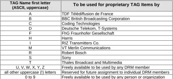
The following list defines special letters to be used as first letters for proprietary TAG Names.
To prevent confusion within DCP-based application protocols for DRM, some of the letters are exclusively assigned for proprietary use by individual organizations.
Table 1: Optional TAG Items
TAG Name first letter
(ASCII, uppercase) To be used for proprietary TAG Items by
A TDF Télédiffusion de France
B BBC British Broadcasting Corporation C Coding Technologies D Deutsche Telekom, T-Systems F FhG Fraunhofer Gesellschaft H Harris
I RIZ Transmitters Co.
M VT Merlin Communications R Robert Bosch
S Sony
T Thales Broadcast and Multimedia
U, V, W, X, Y, Z Freely available to be used by any DRM member
all other uppercase (!) letters Reserved for future assignment to individual DRM members 0 to 9 Freely available to be used by any person or organization
NOTE: The Distribution and Communication Protocol DCP is explicitly free for any use by any person, organization or company. Therefore the exclusivity of proprietary TAG Name first letters from the preceding list only applies to TAG Names defined within one of the DRM-related protocols (like MDI, MCI, SDI, RSCI. etc.). If the DCP is used outside the scope of DRM, any TAG Name may obviously be used by anyone for any purpose.
5.3
DCP's AF Layer
The AF Header CRC, although optional in DCP, is mandatory for all DRM-standardized DCP-based application protocols. Therefore the AF Header's CRC flag ("CF") of the AR field must be enabled (set to 1).
6 DCP
Interface
standards
To provide a defined hardware interface between DCP-capable DRM equipment from different manufacturers, minimum hardware input/output requirements are defined for certain types/categories of DRM equipment. These hardware interface definitions are intended for both:
• local connections (direct connections);
• remote connections (only specifying the first and last piece of the data transport chain).
Every DCP-based application protocol standardized within the DRM consortium may specify its own set of recommended and/or mandatory hardware interfaces. This definition is given within the scope of the application protocol definition.
The present document therefore only specifies the range of possible hardware interfaces together with their
recommended/required setup and configuration. The selection among these interfaces is up to the individual application protocol.
6.1 RS232
The RS232 standard specifies a serial connection. This connection will most probably be used locally. The general characteristics of this protocol/hardware are as follows:
• Standardized as ANSI/TIA/EIA-232 [4];
• Cable length up to 50 metres (for any bitrate with low-capacitance cable: approx. 50pF/m); • Several flow control options (off, XON/XOFF, hardware).
For DCP-based transmission protocols referencing the RS232 protocol as their recommended/mandatory hardware interface, the following settings and restrictions shall apply:
• Connector and pinout according to TIA-457 (9-pin SUB-D) [6];
• DTE (Data Terminal Equipment) presentation (female connector, Transmitted Data is an output).
Note that all equipment has DTE presentation, irrespective of whether it might be considered a source or a sink of the particular application-layer protocol;
• Point-to-point full-duplex mode;
• Minimum supported bitrate must be at least 115 200 bps; • 8N1 (8 data bits, no parity bit, 1 stop bit);
• No flow control.
6.2
Ethernet (IP over Ethernet)
The Ethernet network connection shall be used to transport IP packets (Internet Protocol over Ethernet).
This connection may be used for local and long-distance connection end-points. The following minimum requirements are designed to allow point-to-point or point-to-multipoint unidirectional transmission of a DCP stream in any of the scenarios outlined in clause 4.3 and 4.4.
NOTE: The DCP does not provide any security mechanisms. Security can be implemented in a number of layers. Minimally compliant implementations need not implement application or transport layer security and shall be compatible with network layer security implemented in external equipment, for example IPSEC or other tunnelling mechanisms.
For DCP-based transmission protocols referencing the IP over Ethernet protocol (to transport UDP datagrams) as their recommended/mandatory hardware interface, the following settings and restrictions shall apply.
6.2.1 Transport
Layer
• The mapping of DCP packets to IP is specified in annex B of TS 102 821 [2] which mandates a 1 to 1 encapsulation of PFT or AF packets in UDP datagrams.
• All equipment shall support direct encapsulation of the UDP transport stream in IPv4 datagrams. • All equipment sending DCP streams shall be configurable to set the destination UDP port number and to
specify or identify the source UDP port.
• All equipment receiving DCP streams shall be configurable to set the listening UDP port number (destination UDP port). The source UDP port number (carried in received UDP packets) may be configurable as an additional filtering parameter or the equipment may receive from any source port.
6.2.2 Network
Layer
• All equipment implementing an IP interface shall be capable of operating as an IPv4 host with configurable interface IP address, subnet mask and default gateway.
• All equipment sending DCP streams shall be configurable to set the destination IP address, which can be a unicast or a multicast IP address.
• Equipment receiving DCP streams may be configurable to set the source IP address as an additional filtering parameter or the equipment may receive from any source address.
• All equipment receiving DCP streams shall be configurable to listen on the IP address assigned to the network interface.
• All equipment receiving DCP streams shall be configurable to listen on a configurable IPv4 multicast IP address, in which case the equipment shall maintain membership of the specified multicast group using IGMP.
6.2.3 Link
Layer
For DCP-based transmission protocols referencing the Ethernet protocol as their recommended/mandatory hardware interface, the following settings and restrictions shall apply:
• The interface shall be compatible with IEEE 802.3 [5] 10Base-T LANs using half-duplex multi-port repeaters (hubs);
• The interface should be compatible with IEEE 802.3u [5] 100Base-T LANs using half-duplex and/or full-duplex switches;
• The interface presentation shall be RJ-45 socket, MDI (Medium Dependent Interface) wired to Electronic Industry Association/Telecommunications Industry Association's Standard 568B [7];