Chapter 3
Envelope materials
Porous material placed around a subsurface drain, to protect the drain from sedimentation and improve its hydraulic performance, should be referred to as a drain envelope. It is worthwhile to distinguish between the definition and function of an envelope and that of a filter.
During the early development of design criteria for drain envelopes, existing filter criteria were often used as a basis for research. Hence, the word ‘filter’ is often mistakenly used in reference to drain envelopes. A filter is by definition ‘a porous substance through which a gas or liquid is passed to separate out matter in suspension’ (Merriam-Webster, 1993). Filtration also is defined as ‘the restraining of soil or other particles subjected to hydraulic forces while allowing the passage of fluids’ (ISO 10318, 1990). Hence, a filter, used as a drain envelope, would eventually become clogged because particulate matter would be deposited on or in it, reducing its permeability.
Envelopes have the task to improve the permeability around the pipe, and act as permeable constraints to impede entry of damaging quantities of soil particles and soil aggregates into drainpipes. Yet the majority of small particles of soil material and organic matter, suspended in water moving toward a drain, will actually pass through a properly selected and installed drain envelope without causing clogging. The relatively coarse envelope material placed around the drain should stabilize the soil mechanically and hydraulically, but should not act as a filter.
In addition to the functions described above, drain envelopes can improve the bedding conditions. This bedding function is primarily associated with gravel envelopes in unstable soils. Gravel provides a mechanical improvement in the drain-envelope-soil system, serving as bedding and side support for large diameter plastic pipes (Framji et al., 1987).
Envelope materials used to protect subsurface drains have included almost all permeable porous materials that are economically available in large quantities. Based on the composition of the substances used, they can be divided into three general categories: mineral, organic, and synthetic envelopes.
MATERIALS
Granular mineral envelopes
Mineral envelopes mainly consist of coarse sand, fine gravel and crushed stone, which are placed under and around the drainpipe during installation. If well designed and installed, mineral granular envelopes are quite reliable because they are voluminous and can store comparatively large quantities of soil material without noticeable malfunctioning. As such, they have provided satisfactory long-term service under most circumstances. Traditionally, pit run naturally graded coarse sand or fine gravel containing a minimum of fines is the most common and widely used
Envelope materials 22
drain envelope material. Such material can be as permanent as the soil itself. Properly designed graded gravel envelopes fulfil all the mechanical and hydraulic functions of a drain envelope and are the ideal envelope from a physical standpoint.
Graded gravel should be a homogeneous, well-graded mixture of clean sand and gravel free from silt, clay, and organic matter, which could adversely affect its permeability. The use of limestone particles must be avoided, because a high percentage of lime in gravel envelopes is a source of incrustation. In addition, the gradation of a gravel envelope should be made in accordance to prescribed parameters (Section Specifications for gravel envelopes).
The use of gravel as drain envelope has become a bit controversial. One of the conclusions of a symposium held in Wageningen, The Netherlands in 1986 was the following: ‘Gravel remains for the time being the most reliable filter material. In view of the cost of gravel the development of design criteria for synthetic materials merits the highest priority’ (Vos, 1987). However, at a conference, held in Lahore, Pakistan in 1990 which was devoted specifically to the design and application of envelopes, it was concluded that engineers who were not familiar with synthetic envelopes, were reluctant to recommend their use (Vlotman, 1990). Considering the current tendency, it may be assumed that synthetic envelopes will gradually replace the application of gravel as envelope material in future drainage projects.
Organic envelopes
Organic materials, many of which are by-products of agricultural production, have successfully been applied as drain envelopes. They are voluminous, so they can be used in cases where both particle retention and hydraulic function are important. Organic materials may be applied directly on the drainpipe in the trench as loose blinding material, or may be prewrapped around the drainpipe as Prewrapped Loose Materials (PLMs). An intermediate type of application has been in strip-form, applied on top of the drainpipe. This type of application is now obsolete.
Organic envelope materials include chaff, cereal straw, flax straw, rice straw, cedar leaf, bamboo, corncobs, wood chips, reeds, heather bushes, chopped flax, flax stems, grass sod, peat litter and coconut fibre (Juusela, 1958; Framji et al., 1987).
In northwestern Europe (Belgium, Germany, and The Netherlands), the most common organic envelopes were made from peat litter, flax straw and coconut fibres. The use of fibrous peat litter as a cover layer of drain tiles has been common practice for decades until the end of the 1950s. It was found that the hydraulic conductivity of the peat litter would often decrease drastically due to swelling of the envelope under permanently wet conditions due to e.g. subirrigation (Rozendaal and Scholten, 1980).
During the subsequent period, flax straw has been used. It was applied originally as a cover strip and later as prewrapped envelope. The coarseness of the flax envelope did however not always guarantee the particle retention function. On a much smaller scale, other organic envelopes have been applied. These materials were not always available in the required quantities and their handling was often laborious. The use of straw was not successful because it usually decomposed into a low-permeability layer around the pipe.
At the end of the 1960s, coconut fibre (Figure 16) was introduced (Jarman and Jayasundera, 1975). Being relatively cheap, it soon dominated the market because high quality peat litter became scarce and expensive (Meijer, 1973) and because the flax industry declined. Moreover, the finer coconut fibre was considered a more appropriate envelope material than the
coarser-structured flax straw. Very soon it was discovered that coconut fibres were often subject to microbiological decay (Meijer and Knops, 1977; Antheunisse, 1979, 1980, 1981). The envelopes were usually fully decomposed after two to five years, particularly if the pH of the soil exceeded the value 6. More than a decade later, many farmers complained about mineral clogging of their drains. A research project was set up to investigate the problem of mineral clogging. More than 1000 excavations were made and they confirmed that the mineral clogging problems, although
partly due to the large effective pore size of the coconut fibre envelope, mainly resulted from the decomposition of the organic substances (Blom, 1987).
In the mid-1980s, various attempts were made to retard or stop the decomposition of organic envelope materials. In Germany and in France a so-called ‘Super-Cocos’ envelope was introduced. Its fibres were impregnated with copper sulphate (CuSO4), to kill the bacteria that cause the decomposition (Antheunisse, 1983, 1984). In addition, some envelopes contained tiny copper wires. ‘Super-Cocos’ envelopes had limited success because decomposition was postponed for a few years only. In addition, environmental legislation made installation of ‘Super-Cocos’ illegal in most countries, because the chemical agent leached out rapidly. Coconut fibre envelopes are still being applied in northwest Europe due to their comparatively low price, but their use is declining in favour of synthetic materials.
Organic envelopes have never been popular in countries located in arid climates because the comparatively high soil temperature activates microbiological activity and consequently accelerates their decay. In the irrigated lands of the arid tropics, organic envelope materials usually fail (Van der Molen and Van Someren, 1987). The successful application of organic envelopes in the Scandinavian countries, where mainly fibrous peat and wood chips were used, was due to the reduced microbiological activity at lower soil temperatures.
The service life and suitability of organic materials as envelopes for subsurface drains cannot be predicted with certainty. Eventually, the majority of organic envelopes will decompose, without any serious impact on the structural stability of the surrounding soil. Hence, these materials should be applied only in soils that become mechanically stable within a few years after installation of the drainage system (Van Zeijts, 1992). In addition, organic envelopes may affect chemical reactions in the abutting soil. This process may result in biochemical clogging of the drain. If iron ochre clogging of drains is likely, reluctance with the application of organic envelopes is justified. Even organic matter that is accidentally mixed with trench backfill material may severely enhance the risk of ochre clogging of the drain (Chapter 5).
The rapid decay of coconut fibre envelopes has stimulated the search for affordable, synthetic alternatives. The fact that synthetic envelopes can be more easily manufactured according to specific design criteria than organic ones has played a significant role in this development.
FIGURE 16
Envelope materials 24
Synthetic envelopes
Prewrapped loose materials
A synthetic PLM is a permeable structure consisting of loose, randomly oriented yarns, fibres, filaments, grains, granules or beads, surrounding a corrugated drainpipe, and retained in place by appropriate netting and/or twines. Synthetic PLM envelopes are usually wrapped around the corrugated plastic drainpipes by specialized companies and occasionally in pipe manufacturing plants. The finished product must be sufficiently strong to resist handling and installation without damage.
Synthetic PLMs include various polymeric materials. Fibres may be made of polyamide (PA), polyester (PETP1), polyethylene (PE), and polypropylene (PP). Loose polystyrene (PS) beads can be wrapped around drains as PLMs in perforated foil or in string netting (‘geogrids’ or ‘geonets’). The beads are subject to compression from soil loads that may reduce envelope permeability (Willardson et al., 1980). In various European countries where the drain depth ranges from 0.9 to 1.2 m, the effect
of the soil load is however relatively small. PLM envelopes made from PP (waste) fibres are increasingly used in northwest Europe and in arid areas where they replace expensive gravel.
Information on some envelope materials, which are shown in Figures 17-20, is given below. Figures concerning the market shares of various envelope materials (‘turnover’) are given for The Netherlands, in 1997, for illustrative purpose only. The data are based upon the installed lengths of wrapped drainpipes.
PLM envelopes made from polypropylene waste fibres (PP-300) (Figure 17) are installed almost exclusively in Belgium for private drainage projects (turnover: 6 percent).
PP-450 envelope (Figure 18) is a PLM envelope, manufactured from bulk continuous filaments. These filaments are waste when producing woven PP fibre carpets. In The Netherlands, it is by far the most popular envelope material (turnover: 65 percent).
1 ‘PETP’ is an acronym for polyethylene terephtalate.
FIGURE 17
PLM envelope made from polypropylene waste fibres (PP-300)
FIGURE 18 PP-450 envelope
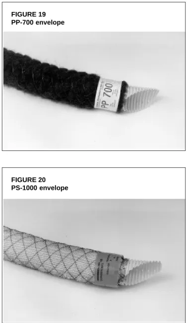
PP-700 envelope is a PLM material, made from new PP fibres (Figure 19). Wrapping of pipes with this envelope is comparatively laborious, hence the high price (turnover: 4 percent). It is mainly used for larger pipe diameters (exceeding 160 mm).
Due to the declining availability of PP waste fibres at competitive prices, waste PA fibres are used occasionally. Contrary to PP fibres, PA fibres absorb water as a result of which the coils may substantially increase in weight. In addition, it is more difficult to process PA fibres to homogeneous prewrapped envelopes because of problems with static electricity.
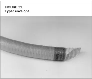
PS-1000 is a PLM envelope material that is manufactured from compressible PS beads in netting (Figure 20) and almost exclusively installed in agricultural areas where flower bulbs are grown (turnover: 7 percent). In these areas, the groundwater contains a relatively high amount of suspended particles, and PS-1000 has proven a very reliable envelope. In this application, the higher price of PS-1000 is a good investment; no farmer can afford to have drainage systems fail.
Synthetic materials deteriorate when exposed to solar (UV) radiation. Experiments with PLM envelopes, made of PP fibres in a temperate climate have indicated that deterioration can be hazardous within three years (Dierickx, 1998b). The speed of the deterioration will be double in semi-arid and arid regions where the average annual radiation is twice that in temperate regions. However, once installed, synthetic PLM envelopes, manufactured from suitable raw material (e.g. recycled PP fibres) are not subject to decomposition. These materials are therefore reliable and affordable substitutes for conventional gravel and organic envelopes.
Prewrapping with loose materials is limited to diameters of 200 mm or smaller. Once prewrapped around drains, PLM envelopes have functional properties that are similar to those of geotextiles.
FIGURE 19 PP-700 envelope
FIGURE 20 PS-1000 envelope
Envelope materials 26
Geotextile envelopes
According to prEN2 30318 (1998), a geotextile is defined as ‘a planar, permeable, polymeric (synthetic or natural) textile material, which may be woven, non-woven or knitted, used in contact with soils and/or other materials in civil engineering for geotechnical applications’. This definition includes application in agriculture since civil engineering incorporates drainage engineering in many countries.
Woven geotextiles are manufactured by interlacing, usually at right angles, two or more sets of yarns, fibres, filaments, tapes, or other elements. Non-woven geotextiles are sheets, webs, or batts, consisting of directionally or randomly oriented fibres, filaments, or other elements. These elements are bonded by mechanical, thermal and/or chemical means. Knitted geotextiles are manufactured by interlooping one or more yarns, fibres, filaments, or other elements.
The fibres, used for production of geotextiles are made from the same raw materials as those used for PLMs, namely: polyamide (PA), polyester (PETP), polyethylene (PE), and polypropylene (PP). The fibres of geotextiles may be monofilaments, multifilaments or tapes; the latter either flat, fibrillated or twisted. The combination of raw materials, fibre configuration and weaving, bonding or knitting techniques results in many types of geotextiles which differ widely in appearance, physical, mechanical and hydraulic properties.
In principle, geotextiles may be used as envelope material for drainpipes because they possess two important properties that are required for a drain envelope, namely water permeability and soil particle retention. Moreover, they facilitate the water acceptance of drainpipes, and they convey water in their plane, alongside the pipe wall. Woven geotextiles, however, are seldom used for the manufacturing of drain envelopes. The only justification for this fact must be their comparatively high price, because
their specifications are indeed favourable.
In some European countries where organic and synthetic PLMs are used, there is persistent reluctance to use geotextiles as drain envelope because it is argued that their fine texture may enhance mineral and ochre clogging. Yet in countries with a geotextile industry like France, Canada and the United States, geotextile envelopes are applied successfully at a large scale. Laboratory experiments, field trials and practical experiences do not give clear
evidence of the clogging risk of properly selected and properly installed fine textured geotextiles. There are, however, circumstances where fine textured geotextiles should preferably not be used (see Chapter 5).
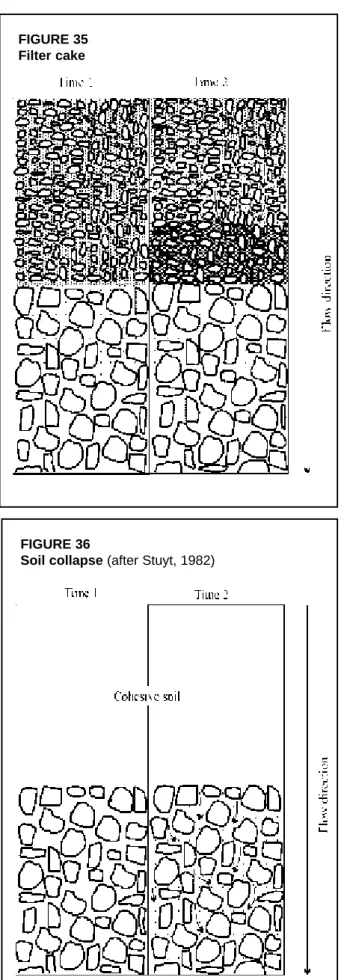
An example of a geotextile envelope is Typar which is the brand name of a non-woven fabric, made of continuous filaments of 100 percent polypropylene without any extraneous binders (Figure 21).
2 prEN is a draft European standard (EN) that is not yet finalized.
FIGURE 21 Typar envelope
Wrapping of drains with geotextiles can be done for any diameter. Geotextile strips can be tied around the corrugated drain, or pulled over it after the edges have been sewn together.
Geotextiles that are exposed to solar natural weathering are also vulnerable to degradation. Rankilor (1992) recommends that exposure of geotextiles to natural weathering may not last longer than two months in temperate regions and only one week in arid and semi-arid regions. Geotextiles, manufactured from organic raw material such as jute will decay in a similar fashion as organic PLMs do, while synthetic geotextiles, like synthetic PLMs, do not.
SPECIFICATIONSFORDRAINENVELOPES
In 1922, Terzaghi developed ‘filter’ criteria to control seepage under a dam. These criteria have since been tested for applicability for envelopes around subsurface drains. Terzaghi recommended that the ‘filter’ material be many times more pervious than the soil base material but that it not be so coarse that the base material would move into the ‘filter’. Terzaghi’s development has served as a basis for much work done since that time on gravel envelope design. For drain envelopes, his design criteria have been tested and modified, but his original concepts have been generally accepted.
Van Someren (FAO, 1972) reported on the research into and the guidelines for selection and application of drainage materials (pipes and envelopes) in various countries. In Belgium and The Netherlands, efforts were made to develop special design criteria for prewrapped loose materials (PLMs). Conventional design criteria were largely determined by analogue models in laboratories, supported by theoretical considerations, and verified by field trials. Monitoring the flow of water and soil particles near prewrapped drainpipes in the field was not an easy task without disturbing the system. In addition, the data, emerging from field experimentation are inevitably blurred because it is site specific. Results achieved at some places are not necessarily replicable at other locations.
Knops et al. (1979) published the first set of comprehensive guidelines for the selection of the then used prewrapped envelopes for use in Dutch soils. Subsequently, a series of research projects and concurrent practical evaluations, carried out by various companies and institutions, have produced design and application criteria for drain envelopes made of PLMs in The Netherlands (Huinink, 1992; Stuyt, 1992a; Van Zeijts, 1992). Many field surveys have been made into the possible factors that affect pipe sedimentation.
Drain envelopes should meet specifications but visual evaluation of materials is also important. Even if the best materials have been used and all specifications are met, a drainage system will not operate properly if envelopes exhibit some shortcomings due to careless wrapping, handling or installation.
Specifications for gravel envelopes
Specifications for gravel envelopes are discussed extensively in numerous publications. This section contains all the major issues. Sound design criteria for traditional granular envelopes (gravel and coarse sand) are available and have been applied successfully in practice (Terzaghi and Peck, 1961; Vlotman et al., in press; Stuyt and Willardson, 1999).
The US Army Corps of Engineers and the US Bureau of Reclamation have made extensive studies of gravel envelopes. The result is a set of specifications for graded gravel envelopes, which have been successfully used by the Soil Conservation Service (SCS, 1973), the US Bureau of Reclamation (USBR, 1993) as well as outside the United States.
Envelope materials 28
The gradation curve of a proposed gravel envelope should be matched to the soil to be drained, as well as to the pipe perforations (Willardson, 1979). In addition, gravel should be internally stable to avoid internal envelope erosion. The general procedure for designing a gravel envelope for a given soil is as follows:
1. make a mechanical particle size analysis of both the soil and the proposed gravel envelope; 2. compare the two particle size distribution curves; and
3. decide, by some design criterion, whether the proposed gravel envelope material is suitable. The involved design criteria consist of rules that prescribe how to derive the particle size distribution, required for a suitable gravel envelope, from particle size distribution data of the soil, in order to guarantee satisfactory service of the envelope.
Terzaghi’s criteria
The first criteria, proposed by Terzaghi (US Army Corps of Engineers, 1941) for what he termed a ‘filter’, are:
•
The particle diameter of the 15 percent size of the filter material (D15)3 should be at least four times as large as the diameter of the 15 percent size of the soil material (d15):D15≥ 4 d15
This requirement would make the filter material roughly more than ten times as permeable as the soil.
•
The 15 percent size of the filter material (D15) should not be more than four times as large as the 85 percent size of the soil material (d85):D15≤ 4 d85
This requirement would prevent the fine soil particles from washing through the filter material. Bertram (1940), Karpoff (1955), and Juusela (1958) suggested similar or modified ‘filter’ design criteria for use with subsurface drains.
Criteria of the US Soil Conservation Service
The SCS (1971) has combined the results of the research on gravel envelopes into a specification for evaluating pit run and artificially graded granular materials for use as drain envelope materials. These specifications are superseded by more recently published specifications (SCS, 1988), which distinguished between ‘filter’ and ‘envelope’. The recommendation for naturally graded materials or a mixture of medium and coarse sand with fine and medium gravel for use as envelope is:
•
D100 ≤ 38 mm.•
D30 ≥ 250 µm.•
D5 ≥ 75 µm.Additional criteria are suggested to prevent excessive fineness of an envelope material, designed to be used for finer textured soils (SCS, 1988):
3 The particle diameter D
x of the x percent size by weight of the filter material is defined as the diameter
•
D15 < 7 d85 but D15≥ 0.6 mm.•
D15 > 4 d15.Criteria of the US Bureau of Reclamation
For rigid, unperforated pipes, the US Bureau of Reclamation treats the joint opening, the length of the pipe section, and the hydraulic conductivity of the envelope material as a unified system. Their Drainage Manual (USBR, 1978, 1993) contains graphs which consider all these factors. Table 1, taken from this manual, gives recommended envelope gradations for soils with different 60 percent passing sizes.
TABLE 1
Gradation relationships between soil and diameters of graded granular envelope material (after USBR, 1978, 1993)
For some fine-textured and salty problem soils in Pakistan, the USBR criteria produced gravel envelopes that were obviously too coarse, allowing excessive amounts of fine soil materials to enter the drains (Vlotman et al., 1990).
Other criteria
Since the design of gravel packs for wells is similar to the design of envelopes for subsurface drains, the criteria developed by Kruse (1962) for gravel packs may also be used for gravel envelopes. These criteria are based on the ratio of the 50 percent size of the pack (envelope) material to the 50 percent size of the aquifer (soil) and on the uniformity of the textural composition (see Chapter 6, Section Physical properties of the soil) of both the aquifer and the gravel. Kruse (1962) observed that sand movement was reduced by decreasing the uniformity of the gravel (i.e. increasing its uniformity coefficient) at all gravel-aquifer ratios and therefore distinguished between uniform soil and gravel pack up to a uniformity coefficient of 1.78 and non-uniform soil and gravel pack for larger
values. The proposed maximum permissible gravel/aquifer particle size ratios for the various combinations of textural composition of both the aquifer and the gravel pack, to prevent excessive movement of aquifer material, are given in Table 2.
Besides the 50 percent ratio of filter to aquifer material, Pillsbury (1967) also used the standard deviation resulting from the difference between the 95 percent and 50 percent sizes of the grading curve of the gravel envelope divided by 1.645, as a
TABLE 2
Largest permissible gravel/aquifer size ratios
(after Kruse, 1962) Textural composition of aquifer Textural composition of gravel pack Gravel/aquifer particle size ratio (D50/d50) Uniform (unstable) Uniform (unstable) 9.5 Uniform (unstable) Non-uniform (stable) 13.5 Non-uniform (stable) Uniform (unstable) 13.5 Non-uniform (stable) Non-uniform (stable) 17.5 Gradation limitations for envelope (diameter of particles, mm)
Lower limits, percentage passing Upper limits, percentage passing Soil, 60% passing (diameter of particles, mm) 100 60 30 10 5 0 100 60 30 10 5 0 0.02-0.05 9.52 2.0 0.81 0.33 0.3 0.074 38.1 10.0 8.7 2.5 - 0.59 0.05-0.10 9.52 3.0 1.07 0.38 0.3 0.074 38.1 12.0 10.4 3.0 - 0.59 0.10-0.25 9.52 4.0 1.30 0.40 0.3 0.074 38.1 15.0 13.1 3.8 - 0.59 0.25-1.00 9.52 5.0 1.45 0.42 0.3 0.074 38.1 20.0 17.3 5.0 - 0.59
Envelope materials 30
criterion for its effectiveness. Pillsbury (1967) presented a graph of the 50 percent size ratio envelope-aquifer vs. this standard deviation which was divided in two zones. Envelopes that fall below the limit line were judged unsatisfactory. Based on observations of some drain envelopes that had failed in the Imperial Valley of California, Pillsbury recommended an envelope-aquifer ratio of less than 24. He concluded that concrete sand, satisfying the appropriate American Society for Testing and Materials (ASTM) standard with a 50 percent size less than 1 mm and a standard deviation greater than 1.0 would be a satisfactory envelope material under most conditions.
Sherard et al. (1984a, b) developed filter criteria for protection of hydraulic structures. While not intended for application in subsurface drainage, the principles may equally well be applied for the design of gravel envelopes. The authors established that if a filter did not fail with the initial flow of water, it was probably permanently safe. Well-graded materials were more successful than uniform materials.
Sherard et al. (1984b) reported on tests with fine textured soils and concluded the following with respect to filter and base soil sizes:
•
Sandy silts and clays (d85 of 0.1 - 0.5 mm) D15/d85≤ 5 is safe.•
Fine-grained clays (d85 of 0.03 - 0.1 mm) D15 < 0.5 mm is safe.•
Fine-grained silts of low cohesion (d85 of 0.03 - 0.1 mm) D15 < 0.3 mm is safe.•
Exceptionally fine soils (d85 < 0.02 mm) D15 < 0.2 mm or smaller is safe.Sands and gravely sands containing fine sand fractions and having a D15 of 0.5 mm or less would be a suitable filter for even the finest clays. For clays with some sand content (d85 > 1.0 mm), a filter with a D15 = 0.5 mm would satisfy the D15/d85≤ 5 criterion. For finer clays, the D15/ d85≤ 5 is not satisfied, but the finer soils tend to be structurally stable and are not likely to fail. Finally, Sherard et al. (1984b) found that well-graded gravely sand was an excellent filter for very uniform silt or fine uniform sand, and that it was not necessary that the grading curve of the envelope be roughly the same shape as the grading curve of the soil. Gravel envelopes that have a D15 of 0.3 mm and a D15/d85≤ 5 with less than 5 percent of the material finer than 0.074 mm will be satisfactory as envelope materials for most problem soils.
Dieleman and Trafford (FAO, 1976) reviewed criteria for selection of gravel envelope materials and included some comments regarding envelope selection for problematic soils. Dierickx (1992b) presented a summary of gravel envelope criteria from the United States and the United Kingdom. This summary clearly indicates that the criteria from various sources do not match, even if one takes into account the difference between ‘filter’ (mechanical) function and ‘envelope’ (hydraulic) function. This fact has prompted new research projects that have yielded new findings, i.e. improvements of existing criteria, which may be used to improve the design gravel envelopes (Vlotman et al., 1997). Another finding of interest was that rounded and angular particles gave equivalent results (Vlotman et al., 1992b).
Specifications for prewrapped envelopes
Prewrapped envelopes may be organic PLM, synthetic PLM and geotextile. Their physical properties such as thickness and mass per unit of surface area are important to check the uniformity of the envelopes, and their conformity with the required design standards. Characteristic opening size, hydraulic conductivity and water repellence determine the hydraulic
properties of prewrapped envelopes. When using loose granular materials, particle size distribution parameters may be used as well. Depending on what kind of drain pipes is used and how envelope materials are wrapped around drainpipes, some mechanical properties of envelopes such as compressibility, abrasion damage, tensile strength and static puncture resistance may be part of the specifications.
In The Netherlands, recommendations for the design and application of PLMs have been developed on the basis of concurrent research projects, theoretical studies, mathematical modelling, empirical studies in experimental fields, analogue modelling in laboratories and practical experience covering a 30-year period (1960-1990) (Stuyt, 1992a).
Thickness
The thickness of prewrapped envelopes serves as a reference for uniformity and conformity. In addition, envelope thickness is found a factor of importance in theoretical analyses as it influences the soil retention capacity, the entrance resistance of drainpipes and the exit gradient at the soil-envelope interface.
The main task of an envelope is soil particle retention. In this respect, design criteria for envelope thickness are irrelevant. Thicker envelopes, however, may have higher porosities, which explain their popularity when chemical clogging is anticipated. Therefore, in the envelope selection procedure, envelope thickness is an important parameter, and often significant in terms of safety.
The thickness of an envelope should be a relevant specification if reduction of entrance resistance is envisaged or if reduction of entrance resistance is the only objective to use an envelope (see Chapter 4, Section Entrance and approach flow resistance). Although a thin envelope may substantially reduce the entrance resistance, the optimal reduction is obtained at a thickness of 5 mm, provided that the hydraulic conductivity of the geotextile is not the limiting factor, which will generally not be the case (Nieuwenhuis and Wesseling, 1979; Dierickx, 1980). A further increase of thickness has no marked influence on the entrance resistance, although the effective radius continues to increase since a comparatively permeable envelope replaces soil material that is usually less permeable.
When envelopes are used to reduce the exit gradient (see Chapter 4, Section The exit gradient), the thickness of the envelope is also a relevant design parameter. The design procedure for envelope thickness, as proposed by Vlotman et al. (in press) shows that even thin geotextiles (≤ 1 mm) may considerably reduce the exit gradient at the soil-envelope interface. The larger the diameter of a drain, however, the smaller hydraulic gradients near the drain will be. Hence, ‘thick’ or ‘voluminous’ envelopes (i.e. thickness > 5 mm) are generally considered to be safer than thin ones, particularly if the drains are occasionally used for controlled drainage or subirrigation (subsurface infiltration).
For PLM, the specification of a minimum thickness was introduced to guarantee a complete cover with a more or less homogeneous envelope. According to the provisional EN-standard (CEN/TC155/WG18, 1994), the following minimum thicknesses are required:
•
Synthetic, fibrous PLMs: 3 mm (e.g. PP fibres).•
Synthetic, granular PLMs: 8 mm (e.g. polystyrene beads).•
Organic, fibrous PLMs: 4 mm (e.g. coconut fibres).Envelope materials 32
The provisional EN-standard further specifies that the mean average thickness of each test piece should not deviate by more than 25 percent from that declared by the manufacturer.
Geotextiles are available from very thin, sheet-like fabrics to rather thick, mat-like materials. Mass per unit area
The mass per unit area is not a selection criterion and therefore not specified. Mass determination can be carried out as a control measure for uniformity and conformity. According to the provisional EN-standard, the mass also may not deviate by more than 25 percent of the mass specified by the manufacturer in order to safeguard a homogeneous product.
Characteristic opening size and retention criterion
The characteristic opening size, derived from the pore size distribution or porometric curve of the envelope, is the most important selection criterion because it determines the effectiveness of the envelope to retain the surrounding soil material.
The retention of soil particles is normally not a problem since very fine fabrics are available. Laboratory research as well as practical experience, however, have revealed that fine envelopes are vulnerable to mineral blocking and clogging. Blocking of an envelope is a decrease of the number of active openings in an envelope that occurs when it is brought in contact with a soil. Clogging, on the other hand, is a decrease with time of the number of active openings in an envelope due to gradual accumulation of particles inside and on its surface, e.g. by particles suspended in turbid water. Therefore, specifications for envelopes should cover both soil retention criteria and criteria to prevent clogging and blocking of the envelope. Intensive research has resulted in criteria for soil particle retention and in recommendations with respect to the problems of blocking and clogging.
The capability of an envelope to retain the soil material is expressed as a ratio of some characteristic pore size of an envelope to some characteristic particle size of the soil in contact with this envelope. In many countries, the O90 is used as the characteristic pore size for organic and synthetic PLMs and geotextiles alike, with a great deal of success.
The O90 of a drain envelope is the pore size for which 90 percent of the envelope pores are smaller. The O90 value is usually obtained by dry sieving of well-known sand fractions, whereby the envelope itself is installed as a sieve and the retained amount of each fraction is recorded. Wet and hydrodynamic sieving, also applied for this purpose, use graded soil and mostly result in smaller O90 values than those obtained with dry sieving.
In 1994, a working group of scientists and engineers in Europe developed a new classification system for PLMs. They introduced three classes of envelopes, depending on the effective opening size of the envelope pores, O90, as follows:
PLM-XF extra fine 100 µm ≤ O90 ≤ 300 µm. PLM-F fine 300 µm ≤ O90 ≤ 600 µm. PLM-S standard 600 µm ≤ O90 ≤ 1100 µm.
In the provisional EN-standard (CEN/TC155/WG18, 1994) only two classes, namely PLM-F and PLM-S have been accepted.
In The Netherlands, practical guidelines for envelope application consider three ‘standard’ O90 values, namely 450, 700 and 1000 µm, 450 µm being by far the most widely applied, and
servicing a great variety of soils. These figures were accepted after Stuyt (1992a), using field data, confirmed evidence of the soundness of the O90 parameter. In Belgium, the O90 of a PLM envelope should range between 600 and 1000 µm for official drainage works.
A frequently used retention criterion, also called filter criterion or bridging factor of an envelope, is the ratio O90/d90. In this ratio, d90 is the particle diameter of the soil in contact with the envelope where 90 percent of the particles, by weight, is smaller. Numerous other retention criteria have been proposed in the scientific literature, which have been published in comprehensive tables, by e.g. Dierickx (1993) and Vlotman et al. (in press). For the design engineer, however, the number of criteria is confusing, the more so because many criteria are contradictory. This fact is self-explanatory, because the criteria were developed under widely different boundary conditions, using many different techniques, equipment and so forth.
Laboratory experiments have unambiguously indicated that the likelihood of soil particle retention is greater when a fabric is thicker. Hence, the characteristic pore size of an envelope may be larger for thicker envelopes, for equal retention. Indeed, retention criteria are linked to envelope thickness.
From laboratory studies with analogue soil models, Dierickx (1987), and Dierickx and Van der Sluys (1990) derived the following simple retention criteria for subsurface drainage applications:
•
O90/d90≤ 5 for ‘thick’ envelopes ≥ 5 mm (PLMs).•
O90/d90≤ 2.5 for ‘thin’ envelopes ≤ 1 mm (geotextiles).For envelopes with a thickness ranging between 1 and 5 mm, the O90/d90 ratio may be interpolated step-wise (Dierickx, 1992a) or linearly (Vlotman et al., in press). The step-wise approach gives one value of O90/d90 for a range of thicknesses and is somewhat more practical than a linear approach which yields a specific value of O90/d90 for each thickness.
Retention criteria for thicknesses of PLMs and geotextiles between 1 and 5 mm, according to the step-wise approach are:
•
O90/d90≤ 3 for thicknesses between 1 and 3 mm.•
O90/d90 ≤ 4 for thicknesses between 3 and 5 mm.Taking into account the retention criterion of a thin envelope, most problems in subsurface drainage will be prevented by envelopes for which O90 ≥ 200 µm.
Field observations of Stuyt (1992a,b) confirmed, in a large extent, the laboratory findings. Stuyt investigated the relation between the O90 size of envelope materials and the thickness of the sediment layer inside the pipes using a miniature video camera five years after their installation. In total, 9634 m of drains were investigated (184 laterals). The pipes had outer diameters of 60 and 65 mm. In The Netherlands, sediment layers exceeding 15 mm are generally not tolerated. The d90 size of the soils was approximately 150 µm in most cases. The correlation between the thickness of the sediment layer inside the pipes and the O90 size of envelope was significant (Table 3). Regardless of the O90 size, voluminous envelopes retained more soil than thin envelopes. Envelopes with larger O90 values, i.e. having larger openings, had poorer soil retention properties. The raw material from which the envelopes were manufactured was not significant. Stuyt (1992a) also found that the above-proposed O90/d90 ratios were valid for the investigated problem soils. Most of the applied envelopes in the experimental fields had rather high O90/d90 ratios (4 to 5).
Envelope materials 34
TABLE 3
Fitted values for pipe sedimentation depth (mm) from a regression model, depending on effective opening size of the envelope pores, O90, and envelope category (thin or voluminous) for observations made at three experimental fields in The Netherlands (after Stuyt, 1992a)
Experiments with turbid water or water charged with soil suspensions indicate that geotextiles are vulnerable to clogging when O90/d90≤ 1 (Dierickx, 1990; Faure, 1991). Hence, the ratio O90/d90 = 1 is the lower limit for soil particle retention, regardless of envelope thickness. The phenomena of blocking and clogging of an envelope are however not so evident, neither in laboratory experiments with soils, nor in field experiments. Therefore, the lower limit O90/d90 ≥ 1 should be considered a recommendation rather than a rigid design criterion.
In the investigation made by Stuyt (1992a), envelopes with O90/d90 near 1 had such low sedimentation depths that the envelopes appeared to act as filters. Hence, for thin geotextiles, the O90/d90 ratio should preferably be near the upper limit. On the other hand, the upper limit, set to 5 for voluminous envelopes (Dierickx, 1987) appears safe for voluminous PLMs since a maximum sedimentation depth of 15 mm is tolerated in 60 and 65 mm outer diameter pipes (Table 3). In soils with some cohesion and, hence, some structural stability, voluminous envelopes with O90/d90 ratios as high as 7 have been applied successfully.
In The Netherlands and in Belgium, the successfully applied retention criterion O90/d90 for envelopes was therefore adopted as the major design parameter. Recommendations for envelope applications are also based on some additional considerations (Huinink, 1992; Van Zeijts, 1992) but the O90/d90 criterion is the most important one.
Locally made fabrics such as carpet backing, which satisfies or may satisfy the above requirements after some modifications, are equally suitable as imported geotextiles. They may therefore be trusted as envelope materials.
Hydraulic conductivity
The hydraulic conductivity of envelopes should be greater than that of the soil in order to reduce the entrance resistance of drainpipes, so that no hydraulic pressure will develop outside
Experimental field
Uithuizermeeden Valtermond Willemstad
O90
(µm)
Thin Voluminous Thin Voluminous Thin Voluminous
250 2.1 0.9 4.5 0.8 9.7 8.5
500 3.9 2.6 6.3 2.5 11. 10.2
1000 5.6 4.3 8.0 4.3 13.2 11.9
In summary, the following retention criteria for both geotextiles and PLMs can be accepted: 1 ≤ O90/d90≤ 2.5 for envelope thickness ≤ 1 mm.
1 ≤O90/d90≤ 3.0 for envelope thickness between 1 and 3 mm. 1 ≤O90/d90≤ 4.0 for envelope thickness between 3 and 5 mm. 1 ≤ O90/d90≤ 5.0 for envelope thickness ≥ 5 mm.
O90≥ 200 µm.
In order to minimize the risk of mineral clogging it is recommended that O90/d90≥ 1; furthermore, envelopes that have O90/d90 ratios near the upper limit of the proposed range of values are generally preferred.
the envelope. From research work of Nieuwenhuis and Wesseling (1979) and Dierickx (1980) it may be concluded that a substantial reduction in entrance resistance is obtained when Ke/ Ks ≥ 10, where Ke is the hydraulic conductivity of the envelope and Ks that of the soil (see Chapter 4, Section Drain with envelope).
The hydraulic conductivity, perpendicularly to or in the plane of envelope, can hardly be a problem because envelopes are much more permeable than the adjacent soil that they have to retain. Even under load, the hydraulic conductivity of compressible envelopes will meet the conductivity requirements.
If, however, envelopes are brought in contact with soil, soil particles may fill pores and partly block their openings as a result of which the hydraulic conductivity at the soil-envelope interface will decrease. In addition, envelopes may clog as a result of particle deposits and/or chemical precipitates, and become less permeable with time. Evaluation of blocking and clogging of envelopes is very difficult. If the lower limit of the retention criteria is taken into account, it may nevertheless be assumed that a favourable hydraulic conductivity ratio is guaranteed. Water repellence
PLMs do not exhibit wetting problems, yet geotextiles may do and water repellence may be a problem. Water repellence means that a minimum water head is required on top of the geotextile, before water starts to flow through it (Lennoz-Gratin, 1992). Once the water has entered the pipe through the envelope, the repellence problem is solved and will generally not return. Wettability resistance also decreases when the geotextile is brought into contact with a moist soil. Research work carried out by Dierickx (1996a) showed that the wetting problem is mainly an initial problem of dry geotextiles. The initially required head for the majority of the tested geotextiles is smaller than 2 mm. For others, it ranges from 5 to 30 mm; one geotextile required an initial head of 64 mm. Although initial water repellence of envelopes does not seem to be widespread, geotextiles that exhibit this phenomenon should not be used as drain envelope to avoid the risk of soil structure deterioration near the envelope due to the initial stagnation of water.
In accordance with the standard on the determination of resistance to water penetration of textile fabrics ISO 811 (1981), a testing procedure has been adopted in the countries of the European Union, to examine geotextiles on water repellence in a qualitative manner (prEN 13562, 1999).
Mechanical properties
Mechanical properties of envelopes are mostly of secondary importance. Geotextiles used as drain envelope do not present specific problems since they are designed for, and are normally used in more challenging circumstances. Moreover, problems that develop occasionally because of handling (e.g. tearing) can be repaired before installation.
The compressibility of compressible envelopes has a major effect on the characteristic opening size and the hydraulic conductivity. The opening size normally decreases in compressed state so that a safety factor is built in automatically. The hydraulic conductivity decreases also, yet the highly permeable nature of the envelope ensures that the hydraulic conductivity ratio is met in compressed state. Moreover, the compressibility of coarser envelopes, composed of coarser fibres, is small. Easily compressible thick envelopes, made of fine fibres should not be used as drain envelope.
Envelope materials 36
Abrasion is the wearing of a part of the envelope by rubbing against another material, either during transportation or installation of wrapped drainpipes. Open spots due to abrasion or whatever other cause, noticed before installation, should be repaired in the field, if they are not out of proportion. Abrasion during installation is less likely to occur because of the short time that the wrapped pipe is routed through the machine.
Geotextiles are wrapped around drainpipes either manually or mechanically; therefore, a certain tensile strength is required. Dierickx (1994) proposed a tensile strength of 6 kN/m, determined according to the wide-width tensile test (EN ISO 10319, 1996). Geotextiles must bridge the corrugations of large drainpipes and may not sag between the corrugations under the soil load. Hence, elongation should be limited, but this requirement is only meaningful if the geotextile is tightly wrapped. Since this has never been a practical problem, elongation requirements have never been put forward.
Resistance to static puncture also is only applicable for drains with large corrugations where a tightly wrapped geotextile bridges the corrugations. The geotextile should withstand the soil load between the corrugations, and puncturing by stones and hard soil clods. These phenomena are simulated by a static puncture test. Through this test, the force required to push a flat plunger through a geotextile can be determined. Since such a problem has never occurred in subsurface drainage so far, no requirements exist.
AVAILABILITYANDCOST
Cost and availability of drainage materials are strongly interrelated. Costs vary continuously since these are dependent on various, partly unpredictable factors like currency exchange rates and the cost of manual labour. For reference, various indications of the cost of drainage materials are given in this Chapter.
The cost of gravel envelopes is not specified here because the local availability of suitable granular material is rapidly declining. In addition, the cost of installation is strongly dependent on local circumstances. In the Integrated Soil and Water Improvement Project (ISAWIP) in Egypt, local gravel envelopes were four times as expensive as imported Canadian synthetic fabric envelopes (Metzger et al., 1992). In the Fourth Drainage Project of the International Waterlogging and Salinity Research Institute (IWASRI) of Pakistan, the cost of synthetic envelopes was found to be 40 percent lower than that of gravel envelopes. Installation of synthetic envelopes was easier and faster, too (IWASRI, 1997). Thus, even if the price of gravel is competitive, it goes hand in hand with high costs of fuel and manual labour. It is therefore irrelevant to consider the price of the raw material only. Vlotman et al. (in press) quote costs of gravel envelopes (material and transport) in various projects in Pakistan. For all projects, the costs of material and shipping of synthetic materials was below the cost of gravel. Unfortunately, the high cost of gravel installation compared to that of installing prewrapped pipes is not included in this analysis. The cost/benefit ratio is certainly in favour of PLM envelopes and geotextiles. PLM envelopes, manufactured from PP fibres and coconut fibres dominate the market in northwestern Europe. PLM envelopes, manufactured from peat fibres are now used only occasionally.
An indication of the cost of drainage materials, i.e. pipes and PLM envelopes, in The Netherlands is given in Table 4. Absolute prices are not given. Instead, the relative cost of pipe and envelope material is specified for various pipe diameters and envelope materials. The figures
are based upon corrugated PVC pipe, and are quoted for contractors with high rates of turnover. The price of installation of one metre of wrapped drainpipe more or less equals that of one metre of unwrapped 60 mm pipe.
From Table 4, it can be seen that the price of even the cheapest PLM envelope comprises a substantial part of the price of a pre-wrapped pipe. This is particularly true for smaller diameter pipes. In 1998, there was a slight upward tendency of the price of polypropylene waste fibres in The Netherlands. These fibres are no longer available in such huge quantities as they used to be in the past. Dutch pipe wrapping companies are experimenting with other synthetic waste materials in an effort to be able to market competitive envelopes in the years to come.
TABLE 4
The relative cost of PLM envelopes, expressed as a percentage of the cost of the envelope plus a corrugated PVC pipe together as a prewrapped product, in The Netherlands in 1998. The cost of installation is not included. The O90 size is specified within brackets
The selection of an envelope material is determined by various factors. The price is obviously important. The ease of handling of the material is also a factor of consideration. Coconut fibre envelopes will release substantial amounts of dust particles during handling and installation, particularly in dry weather; PP fibre wrapping does not. Previous favourable experiences of farmers are important: they tend to ask for a similar envelope when ordering again.
REVIEWOFLOCALEXPERIENCEONDRAINAGEMATERIALS
Adequate characterization of soil properties, field conditions (e.g. groundwater table depth) and physical properties of envelope materials is essential. In this context, the term ‘problem soils’ is rather vague and calls for further definition. This also holds for envelope materials: a generic description like ‘PP envelope’ is meaningless since it may cover the whole range from thin geotextiles to voluminous PLMs.
In an envelope selection process, a systematic comparison with experience gained elsewhere is generally very useful. Synthetic envelopes, either PLMs or geotextiles, have proven to be reliable and are successfully applied in Europe, the United States, and Canada for the last 20 years. These materials have also been used satisfactorily in large-scale field experiments in Egypt and Pakistan. In the latter country, they have also been used as envelope for interceptor drains. This proves the transferability of synthetic materials from one region to another.
In Framji et al. (1987), the use of envelope materials is summarized for a great number of countries. These data are included in the Table 5, which is supplemented with additional
Relative cost of various envelope materials Pipe diameter (mm) Coil length (m) Typar (270) Coconut fibres (1000) Polypro-pylene waste fibres (300) Polypro-pylene waste fibres (450) Poly-ester knitted sock (400) Coconut fibres (700) Poly-styrene beads in netting (1000) Polypro-pylene fibres (700) Polypro-pylene fibres (heavy) (700) 50 200 43 46 47 49 50 54 - 60 75 60 150 40 50 44 46 46 50 71* 57 73 65 150 35 39 39 41 41 46 62 52 69 80 100 33 37 39 41 41 43 - 49 65 100 100 31 40 40 42 37 43 - 47 64
Envelope materials 38
TABLE 5
Drainage materials used in a number of countries
Material Pipes Mineral
envelopes
Organic envelopes Synthetic
envelopes C l a y C o n c r e t e P l a s t i c S a n d a n d g r a v e l S l a g G l a s s f i b r e c l o t h C h a f f S t i c k s C o c o n u t f i b r e s S a w d u s t S t r a w R i c e s t r a w C e d a r l e a f B a m b o o P a l m f i b r e s P e a t f i b r e s K n i t t e d s o c k G e o t e x t i l e s S y n t h e t i c w a s t e f i b r e s Australia Belgium Canada China Colombia Costa Rica Cuba Czech Rep. Denmark Egypt Ethiopia Germany France Hungary India Iran Iraq Israel Ireland Japan Jordan Netherlands Pakistan Peru Poland Portugal Romania South Africa Spain Thailand Turkey Uganda USA Zambia Zimbabwe
information from other sources, included that provided by the participants of the International Course on Land Drainage (Wageningen, 1997-1999). Some local experiences that are considered to be informative are briefly discussed below.
Arid and semi-arid zones
In the Melka Sadi Pilot drainage scheme in Ethiopia, trials were conducted for evaluating drainage envelopes. Three different envelopes were tested in a pilot scheme, comprising locally available red ash, gravel and a factory made fabric filter. The cost of gravel was six times that of fabric filter. The performance of both gravel and red ash were superior to that of the fabric filter (Woudeneh, 1987).
In Egypt, voluminous envelope materials that are produced locally, namely PP and PA waste fibres (O90 of 330 and 400 µm, respectively) performed satisfactorily (Dierickx, 1992a). Occasionally, however, the wrapping of drainpipes proves to be poor. The yarn of prewrapped pipes was slack and the envelope material did not fully cover the pipe. After shipping and handling in the field, bare spots emerged at many places. In addition, taping of the envelope at either end of coils was sometimes inadequate as a result of which the envelope was loose (DRI, 1997).
In the north-western irrigation districts of Mexico, locally produced corrugated PE pipes are used, with a diameter of 100 mm for laterals and 150 mm for collectors. They must comply with ASTM standards (Chapter 9). Collector pipes are approximately twice as expensive as laterals. Polyester sock is used as drain envelope, the cost of which is 30 percent of the price of the wrapped pipe.
An encouraging result of recent envelope testing projects in Pakistan is that synthetic materials, produced in Pakistan, performed well in the laboratory and have shown their potential for field application. It is not unlikely that IWASRI will eventually recommend the Pakistan Water and Power Development Authority (WAPDA) to replace gravel envelopes with locally manufactured synthetic materials. Locally manufactured materials were found to outperform finer local and imported materials, and hence are subjected to additional field trials. In the Mardan Scarp salinity control and reclamation project in Pakistan, Dierickx et al. (1995) recommend envelopes with an O90 ranging from 200 to 400 µm.
In Peru, gravel and coarse sand are available everywhere at very reasonable cost, and have been successfully installed by hand and trenching machines. The use of clay and concrete tiles has not been very successful. Many soils are very unstable, and accurate installation of drains was complicated. Installation by hand was quite slow, and the width of excavation at the soil surface was 6 to 15 times that of the trench box of a trenching machine. Concrete pipes were expensive, because they had to be made from sulphate resistant cement. Most Peruvian soils that are suitable for agriculture have a very high content of calcium sulphate. Furthermore, the rate of production of concrete pipes was quite low. Between 1983 and 1985, 400 km of 65 mm and 100 mm corrugated pipe was installed. These pipes were manufactured in Peru with an extruder, imported from Europe (De la Torre, 1987).
Humid Tropics
In Costa Rica, corrugated pipes were imported from the United States to drain fruit plantations, mainly bananas, notably in medium to coarse sands. In finer soils with low structural stability, the pipes were mostly prewrapped with geotextiles, e.g. spun bonded polyamide (Murillo, 1987).
Envelope materials 40
In India, drainage materials are produced locally. Agricultural drainage systems are solely installed on an experimental basis. In heavy clay soils, drains are installed without envelope material, and the systems perform satisfactorily. Locally made geotextiles are used with success; problems are rarely encountered (Oosterbaan, 1998). In the mid-1980s, the functioning of subsurface drainage systems was investigated in pilot areas, using clay tiles, installed in manually excavated trenches (Singh, 1987). In 1998, the majority of the drainage systems is still being installed by manual labour.
Temperate zones
In Belgium, the use of clay tiles was discontinued in 1975 when their application was superseded by corrugated PVC pipes. Since a potential risk of mineral clogging exists in nearly all soils, envelopes are used everywhere. Envelope materials have evolved from flax straw and coconut fibres to loose synthetic fibres. Currently, loose synthetic PP fibre wrapping is almost exclusively used, but coconut fibre wrapping is still available.
In the Scandinavian countries, sawdust from conifer trees is very often used as an envelope material for agricultural subsurface drainage systems. In unstable soils in Denmark the pipe drain is protected against mineral clogging by a synthetic sheet beneath the pipe, and gravel or sawdust aside and on top of the pipe. In Norway, 50 percent of the sawdust has usually decayed after 20 years. Still, some drains have a service life of over 30 years, which will be due to the low temperatures in Scandinavia. The sawdust is applied in a 50 to 70 mm thick layer (Mortensen, 1987).
Approximately 60 percent of the installed drainpipes in the then West-Germany were prewrapped (Eggelsmann, 1982). Organic envelopes like peat, rye straw and coconut fibre wrappings have been extensively used. Even envelopes made from tannin-containing wood chips to prevent or reduce ochre formation have been developed (Eggelsmann, 1978). Various kinds of synthetic fibre and granule wrappings have been applied, yet geotextile and loose PP fibre wrappings are the most widely used materials.
Only 5 percent of the drainpipes installed in France need an envelope material. Envelopes have evolved simultaneously with drainpipes and drainage mechanization. Originally, coconut fibre wrappings have been widely used. The risk of microbiological decay of the coconut fibre wrapping has prompted the introduction of loose synthetic fibre wrappings and, at a later stage, geotextiles. Currently, geotextiles are used almost exclusively (Lennoz-Gratin, 1987).
In The Netherlands, the recommendations for the selection of PLMs are as follows (Huinink, 1992; Van Zeijts, 1992):
•
Envelopes containing peat fibres and ‘PP-450’ should not be used in case of possible iron ochre hazard and/or if the drains are also used for subsurface irrigation purposes during the summer season.•
Mature or ‘ripened’ clay soils with a clay content greater than 25 percent do not require envelopes.•
For most other soils, such as immature clay soils with a clay content greater than 25 percent, (loamy) sand, (sandy) loam, silt loam and peat soils, any envelope may be selected following the recommendations, specified in Table 6.•
Exceptions are made for clay soils with a clay content below 25 percent, silts and very fine sands which should be drained with ‘PP-450’ or, in case of iron ochre, with ‘PP-700’ only.TABLE 6
Applicability of the most popular prewrapped drain envelopes in The Netherlands (adapted from Huinink, 1992)
In The Netherlands, ‘thin’ envelope materials are used with great caution only, and only in highly unstable very fine sandy soils (median soil particle diameter < 120 µm). For a variety of reasons, this category of envelopes has never become very popular. The price of thin envelopes is not competitive, and most farmers simply prefer envelopes to have a ‘visible and substantial thickness’ because they are convinced that such envelopes provide better service than thin ones. Reliable data, retrieved from pilot area research projects that convincingly prove that this ‘traditional’ viewpoint is not always justified, have not had an appreciable effect. Tradition is indeed a strong factor when it comes to selecting drainage materials, particularly envelopes.
In the Marismas area, located in the Guadalquivir estuary in southern Spain, clay pipes are mainly used although corrugated plastic pipes are installed as well. The clay pipes have an inside diameter of 80 mm, yet a square outside circumference with a small longitudinal hole in each corner, which is introduced to assure thorough heating of the clay during the manufacturing process. The corrugated PVC drains have a diameter of 50 mm. The cost difference between clay and PVC drains is small, and farmers, therefore, prefer the larger diameter clay pipes (Martínez Beltrán, 1987). Drains are installed during the dry season when the groundwater table is below drain level. Drains do not require envelopes because the Marismas soils are very stable due to their clay content greater than 65 percent. Mineral clogging of drainpipes has never been observed except for drains whose outlets into open collectors were submerged during periods of heavy rainfall.
In silty loams and loamy clay soils of the Ebro basin in north-eastern Spain, corrugated PVC drains with coconut fibre wrapping have been installed in the seventies. There is no information on the performance of these drainage materials. Corrugated PVC drains and synthetic fibre wrapping have been used in the sandy soils of the Ebro delta as well.
Envelope material Soil type1
Soils with clay content > 25% down
to drain depth
Soils with clay content <25%, loams and very fine-textured soils, structurally unstable sands (median particle diameter < 120 µm) Loamy sands and eolic deposits Sandy soils (median particle diameter > 120 µm) Peaty soils and peats with clayey topsoils
Soil profile matured to drain depth?
Yes No Yes No
‘voluminous’ envelopes
(i.e. thickness ≥ 1mm)
Cocos (O90 = 700 or 1000 µm) None
2 Yes Yes Yes Yes
Peat/cocos mix, peat fibres None2 Yes3 Yes3 Yes3 Yes3 Polypropylene fibres 450 µm None2 Yes3 Yes3 Yes3 Yes3 Yes3 Yes3 Polypropylene fibres 700 µm None2 Yes --4 --4 Yes Yes Yes
Polystyrene beads None2 Yes Yes Yes Yes
‘thin’ envelopes
(i.e. thickness < 1mm) Glass fibre sheet, Cerex, Typar, knitted sock envelope
None2 Yes3,5 Yes3,5
1 In layered soil profiles, envelope selection should be based on the layer with the lowest clay content. 2 No envelope required; soil is structurally stable and the risk of mineral clogging of the drainpipe is small. 3 Do not install this envelope material if there is a risk of iron ochre clogging, or if the drains are used for
controlled drainage or for subirrigation purposes.
4 Use this envelope material only if there is a serious threat of iron ochre clogging the drains. 5 Do not use a thin envelope if the soil profile to drain depth contains peaty layers.
Envelope materials 42
Chapter 4
Water flow into and inside the drain
FLOWTOWARDSTHEDRAIN
According to Ernst (1954), the flow towards a subsurface drain can be described by a vertical flow (from the groundwater level downward to drain level), a horizontal flow towards the vicinity of the drain, a radial flow to the drain and an entry into it. Each of these flows is subject to a corresponding resistance (Figure 22a). For steady-state flow, the total resistance can thus be roughly classified into vertical, horizontal, radial, and entrance resistances. These resistances can be measured by strategically located piezometers (Figure 22b). Piezometers consist of unperforated narrow pipes with a short filter at the bottom end in which the water level represents the hydraulic head in the soil near the filter end. Differences in heads are a measure of the resistances mentioned. The total loss of head, ht, is the sum of all differences indicated in Figure 22b:
•
The vertical head loss, hv, is the difference in water level between piezometers 1 and 2, located midway between two drains, with filters at respectively groundwater level and drain depth.•
The horizontal head loss, hh, due to (mainly) horizontal flow towards the drain, is the difference in water level between piezometers 2 and 3, with filters at drain level respectively midway between two drains and in the vicinity of the drain.FIGURE 22
Flow resistances towards a drain flowing at full capacity (a) and their corresponding head losses (b)
Water flow into and inside the drain 44
•
The radial head loss, hr, is the difference in water level between piezometers 3 and 4, with filters at drain level respectively some distance away from the drain and at the drain.•
The entrance head loss, he, is the difference in water level between piezometer 4 and an open standpipe in the drain.The relationship between head loss and corresponding resistance is given by:
h* = q L W* (1)
where h = difference in head (m); L = drain spacing (m); q = specific discharge (m/d); W= resistance (d/m); and
* = subscript v (vertical), h (horizontal), r (radial), e (entry) or t (total). Thus the total head loss is:
ht = hv + hh + hr + he (2) Sometimes the resistances W are replaced by the dimensionless quantities α which are independent of the hydraulic conductivity of the soil:
α* = K*W* or W* = α* / K* (3) whereK = hydraulic conductivity (m/d); and
α = geometrical factor (dimensionless). Hence, the total head is given by:
ht = q L (Wv + Wh + Wr + We ) = q L (αv / Kv + αh / Kh + αr /Kr + αe / Ke ) (4) This and other drainage theories are used for calculating drain spacings. They are based on a set of assumptions concerning the drain and the physical properties of the soils involved. Although these assumptions are approximate, the outcome is usually sufficient for practical applications. One of these assumption is that of an ‘ideal drain’, without entrance resistance, whereby the drain is considered as an equipotential. Generally, it is assumed that the drain surround (envelope material and loosened soil in the trench) has such a high hydraulic conductivity compared to the undisturbed soil, that the entrance resistance may be neglected. Practical experience has shown that this cannot always be taken for granted. There is still need for a query, both theoretically and empirically, in which cases substantial entrance resistances may be encountered.
Ponding and excess soil water during heavy rains, in spite of the presence of a drainage system, may also result from a low permeability layer near the soil surface that causes a suspended or perched water table. Another cause may be compaction due to heavy machinery, to slaking during heavy rains and, on sports fields, to playing actions. This low permeability layer simply prevents the water from reaching the groundwater table, but has nothing to do with the subsurface drainage system itself.
Procedures and programs for the design of subsurface drainage systems are in preparation by FAO. Therefore, this analysis will be limited to the influence of the entrance resistance and pipe flow on drain performance.