FLOWCACHE: A CACHE BASED APPROACH FOR IMPROVING SDN SCALABILITY
A Thesis by ATIN RUIA
Submitted to the Office of Graduate and Professional Studies of Texas A&M University
in partial fulfillment of the requirements for the degree of MASTER OF SCIENCE
Chair of Committee, Guofei Gu Co-Chair of Committee, Alex Sprintson Committee Member, Radu Stoleru Head of Department, Dilma Da Silva
May 2015
Major Subject: Computer Science
ABSTRACT
Software Defined Networking (SDN) is a novel paradigm for designing, developing and managing communication networks. SDN separates the traditional network control and data planes, centralising the control plane activities of the network in software based SDN controllers. This approach enables the network operators to interface with a logically centralized device to operate, configure and manage a large complex network. The SDN concept defines the data plane as a set of abstractions and provides a standardized protocol to interact with these abstractions. Owing to its significant advantages, this concept has gained popularity especially among the data center operators and hardware equipment manufacturers, and is slowly being adopted by the industry.
However, the paradigm shift from the traditional networking model to SDN-type architectures poses several major challenges. In an SDN architecture, the routers and switches frequently generate requests to the controller. In particular, a request is generated for every new flow. The controller needs to respond promptly to the requests to ensure correct and efficient operation of the network. Even a moderately sized network with dynamic flows will place a high volume of demand on the con-troller. Increased controller pressure results in increased response times, leading to higher latencies in data-plane to control-plane communication and affecting efficiency of the entire network. This can lead to a scenario where the controller becomes a major bottleneck in the network.
Several solutions have been proposed to address this problem using distributed and hierarchical controller designs. In contrast, in this thesis we propose to address this problem from a different perspective. In particular, we leverage the widely
used tools in the design of memory architectures, such as caching to improve the efficiency of the SDN architecture. In this work, we first propose to augment an SDN architecture with aflowcache. The flowcache serves as a transparent layer in between the controller and the switch. It acts as a cache to the controller, temporarily storing flows sent across the management link, thus reducing access time for future requests of similar flows. Next, we analyze the properties and uses of flowcache. Finally, we compare different design choices for the flowcache and evaluate the benefits of introducing a flowcache in an SDN architecture.
DEDICATION
ACKNOWLEDGEMENTS
I would like to express my sincere gratitude to my advisor Dr. Alex Sprintson for his guidance and constant support throughout my graduate school life. I would also like to sincerely thank Jasson Casey for his advice. Under their mentorship my short span as a master’s student has been both enjoyable and fruitful. I am very grateful for the help I received from my colleagues from Flowgrammable, Colton Chojnacki, Muxi Yan, Luke Mchale, Prithviraj Shome and Srikanth Nomula for this work. Finally, I want to thank Dr. Guofei Gu and Dr. Radu Stoleru for having served as my Co-Chair and committee member respectively.
At the end, I want to thank my family and friends for their support and motiva-tion.
NOMENCLATURE
DHCP Domain Host Configuration Protocol FIFO First In First Out
IP Internet Protocol LAN Local Area Network LRU Least Recently Used
OF Open Flow
ONF Open Networking Foundation QoS Quality of Service
SDN Software Defined Networks TCP Transmission Control Protocol TLS Transport Layer Security UDP User Datagram Protocol VLAN Virtual Local Area Network WAN Wide Area Network
TABLE OF CONTENTS Page ABSTRACT . . . ii DEDICATION . . . iv ACKNOWLEDGEMENTS . . . v NOMENCLATURE . . . vi
TABLE OF CONTENTS . . . vii
LIST OF FIGURES . . . ix
LIST OF TABLES . . . xi
1. INTRODUCTION . . . 1
1.1 Motivation . . . 1
1.2 Related Work and Background . . . 3
1.2.1 OpenFlow Overview . . . 4
2. FLOWCACHE DESIGN . . . 12
2.1 Flowcache Architecture . . . 12
2.1.1 Flowcache Properties . . . 13
2.1.2 Flowcache Location . . . 14
2.1.3 Handling Openflow Messages . . . 17
2.2 Eviction in Switch . . . 20 2.2.1 IntraTable Dependencies . . . 21 2.2.2 InterTable Dependencies . . . 23 2.2.3 Eviction Strategies . . . 26 2.3 Transparency Property . . . 31 2.4 Hierarchy of Caches . . . 32 3. IMPLEMENTATION . . . 34 3.1 Challenges . . . 34 3.2 Connection Setup . . . 35
4. EXPERIMENTAL SETUP . . . 39
5. RESULTS AND DISCUSSION . . . 41
6. CONCLUSION . . . 45
7. FUTURE WORK . . . 46
LIST OF FIGURES
FIGURE Page
1.1 OpenFlow: Controller and Switch . . . 5
1.2 Abstractions in a Switch . . . 6
1.3 Lifecycle of a Packet in the Switch Dataplane . . . 7
1.4 Structure for Match in OpenFlow 1.3 . . . 8
1.5 Structure for OpenFlow Header . . . 9
1.6 Message Structure for PacketIn in OpenFlow v1.3 . . . 10
1.7 Message Structure for PacketOut in OpenFlow v1.3 . . . 10
1.8 Message Structure for FlowMod in OpenFlow v1.3 . . . 11
1.9 Message Structure for TableMod in OpenFlow v1.3 . . . 11
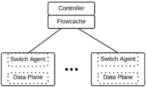
2.1 Abstract SDN Model with Flowcache . . . 12
2.2 SDN Architecture with Flowcache . . . 13
2.3 Flowcache Location - Controller . . . 14
2.4 Flowcache Location - as a Middle Box . . . 15
2.5 Flowcache Location - Part of LAN Connecting the Switches . . . 16
2.6 Flowcache Location - Switch . . . 17
2.7 Flow Modification Scenario . . . 18
2.8 Query Scenario . . . 19
2.9 Synchronization Scenario . . . 20
2.10 Intra Table Dependency Graph . . . 23
2.12 Table Highlighting Stale Entries . . . 24
2.13 Reference Edges Between Flow Entries . . . 25
2.14 Eviction Scenario in a Switch . . . 28
2.15 Message Structure to Configure Switch for Eviction in OpenFlow 1.4 29 2.16 Hierarchy of Caches - in Memory Systems and SDN Architecture . . . 32
3.1 Stateful Connection Setup in Flowcache . . . 36
3.2 A Flow Table in Flowcache . . . 37
3.3 Internals of Flowcache . . . 37
4.1 Experimental Setup . . . 39
5.1 Normalized Throughput of our SDN Model . . . 41
5.2 Measuring the Load on Controller for Varying Flow Table Size . . . . 42
5.3 Performance Measurement Using Different Eviction Policies . . . 43
LIST OF TABLES
TABLE Page
2.1 An Example OpenFlow Flow Table . . . 22 2.2 Flags for TableMod Eviction Property . . . 29 3.1 OpenFlow Messages Intercepted by Flowcache after Connection Setup 38
1. INTRODUCTION
1.1 Motivation
Software Defined Networking (SDN) has recently gained significant attention from the networking industry. The core principle behind the SDN model is to provide flex-ibility in both designing and managing communications network through a logically centralized controller. In an SDN architecture, the controller maintains a view of the underlying network and installs flows in the forwarding elements (switches) to route traffic along specific paths. This approach provides the network administrators the capability to configure and program the networking devices to meet the requirements of the specific network applications.
Each SDN application maintains a specific minimum requirement on the number of flows that has to be resident on the switch for it to perform efficiently. For a large number of applications this count grows multifold. Since each hardware switch has limited capacity, it can store only a small number of flows. This forces the controller to reinstall flows on a frequent basis, increasing the overall latency between the data and the control plane. Therefore, an increase in the number of applications running on the controller leads to substantial performance degradation of the entire system. A simple proposed solution can be to implement the switches entirely in software which enables them to have unbounded table sizes. Software switches like Open vSwitch [8] have recently been developed. These switches are not constrained by the flow table capacity, but are limited by the number of ports. Additionally, their performance is degraded by the slow processing of packets in the software.
Hardware switches implement packet processing pipelines in hardware, leading to significant performance improvements. However these switches are expensive.
They typically implement flow tables using Ternary Content Addressable Memory (TCAM) for faster classification of packets. Each packet is matched against all the flow rules in parallel, and the highest priority match is selected. Today’s commodity switch can support about 2,000 to 2,000,000 flow rules. However, the higher cost and excessive power requirement of TCAM’s makes it difficult for commodity switches to support a high TCAM count. Hence, commodity switches are unable to support a large number of flows. Current research projects like FastPath [7], which rely on hashing of tables, can considerably improve the performance of a software switch, but are still slow compared to TCAMs.
In this thesis, we apply the principle of caching to the design of flowcache for the SDN model. A cache is a transparent component which stores recently accessed and pre-fetched data, to service all future requests for that specific data faster. On a cache hit, the request is serviced by reading the data from the cache, otherwise the data is fetched from its actual storage location. Caching has seen widespread use especially in computer memory architectures. There has been extensive research on the different designs of caches, hierarchical organization of caches, and various techniques that can be used to make caching more effective. We take advantage of the research in this field to provide a robust architecture for our SDN model.
In our work, we propose a novel SDN architecture for access networks. Ac-cess networks interconnect the end-users to the core network using wireless and wired connection interfaces. These networks are limited by hardware resources. The slow bandwidth across the management channel and use of lightweight commodity switches characterize the limitations of an access network. Efficient management of these resources becomes necessary from the perspective of the end-users. Our SDN model focuses on managing these hardware resources to achieve maximum
perfor-In our SDN architecture, a flowcache sits transparently between the controller and the switches. Theflowcache acts as a software cache for the logically centralized controller, by storing all the flows recently installed into the switch. Since flowcache is implemented as a software based cache, it has the ability to store a large number of flows. This gives the controller an abstraction of a much larger switch which can store an unbounded number of flows, thus satisfying the table space requirements of all the applications concurrently running on the controller. In this thesis, we discuss the different design choices and tradeoffs of flowcache and draw a comparison between the memory system cache and the flowcache. Finally we evaluate the performance improvement in throughput and latency achieved by inserting a flowcache in an existing SDN architecture.
1.2 Related Work and Background
There have been many studies that have tried to address the scalability problem in an SDN architecture. These studies have identified three separate bottlenecks in an SDN model - the controller, the communication channel between the control plane and data plane, and the hardware switch.
In Kandoo [2], the authors propose a hierarchical controller design, where the lo-cal applications are offloaded to the lolo-cal controllers, while the applications requiring global view of the network, execute on a centralised one. The design requires main-tenance of complex data structures between the global and local controllers. Onix [4] and Hyperflow [14] present a distributed controller design, where each controller maintains a different set of switches and communicates among themselves to share a global view of the network. The state distribution protocol presented in Onix [4] to share the global view of the network is complex and introduces the challenges faced in a distributed system.
Difane [16], presents a solution to reduce the traffic in the controller-switch chan-nel. Their solution partitions the flows among a set of switches and installs appro-priate rules, to selectively direct packets to specific switches. The solution requires extensive TCAM usage, where the secondary switches act as cache devices. AVANT-GUARD [10] tries to reduce the switch to control plane traffic, especially when the network is under attack. It uses the concept of SYN cookies to detect false con-nection requests, and introduces event-triggers for faster discovery and response to changes in the data plane traffic.
The work by Katta and Rexford [3] tries to solve the flow capacity problem for data-center specific networks by extending the solution presented in Difane [16]. It exploits the large data capacity of software switches by using them as the secondary cache devices. It, also selectively redirects data packets to specific software switches on a hardware switch miss. However, their solution incurs a significant overhead by creating its own rules. Additionally, with that solution the throughput is limited by the channel bandwidth available across the hardware and software switches.
In this thesis, we present a novel architecture, that leverages the principle of caching to achieve the required performance goals. Our SDN architecture targets the edge networks which are limited by software processing power. The flowcache acts as a proxy component which avoids the complexity of creating new rules by installing rules which are inserted by the controller.
1.2.1 OpenFlow Overview
OpenFlow is an implementation of the SDN paradigm which has recently gained popularity. Starting 2008, twelve different versions of the OpenFlow protocol have been published by the Open Networking Foundation, with OpenFlow version 1.5 as their most recent iteration. Each version of the protocol adds on new abstractions
and structures to efficiently manage the OpenFlow enabled switches.
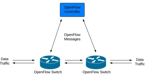
OpenFlow is an application layer communication protocol that operates above the TCP/TLS connection. It provides the logically centralized controller an efficient way to program the underlying switches to route packets through the network. OpenFlow separates the control plane and the data plane of a switch in an effort to centralize the control plane activities of a distributed network. Figure 1.1 depicts a basic OpenFlow model.
Figure 1.1: OpenFlow: Controller and Switch
OpenFlow provides an interface that enables the controller to configure and man-age the underlying network. Using OpenFlow, a controller installs, modifies and deletes rules (flows) in the switch’s forwarding table. Packets are routed in the network using the forwarding rules installed in the switches.
An OpenFlow-enabled switch is the data-plane component of the SDN architec-ture. Each switch maintains a data-plane channel to forward packets and a switch-agent to interact with one or more controllers. The data-plane is composed of a set
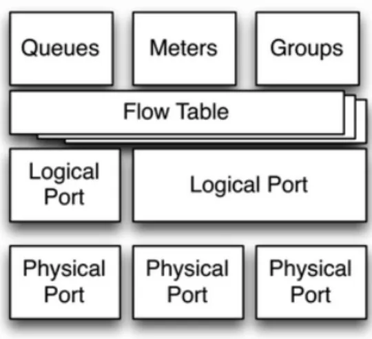
of abstractions namely ports, flow tables, groups, queues and meters. These config-urable abstractions are administered by the controller to efficiently route the traffic through the network. The different abstractions in the SDN model are shown in Figure 1.2.
Figure 1.2: Abstractions in a Switch1
In Figure 1.2, ports are the ingress and egress points through which all messages enter and leave the switch. Flow tables are used for classification of data packets and application of flow policy decisions. The queue abstraction helps an OpenFlow switch to provide Quality of Service (QoS) support, while the meter abstraction is used to limit the packet flow. The group abstraction is an aggregation of flows used mostly for egress processing. In our SDN architecture, we limit flowcache to the abstractions - flow tables.
Each OpenFlow switch contains a fixed number of flow tables. A flow table is composed of a set of fields used to match an incoming packet, and a set of instruc-tions associated with each such match. All data packets entering the switch behave
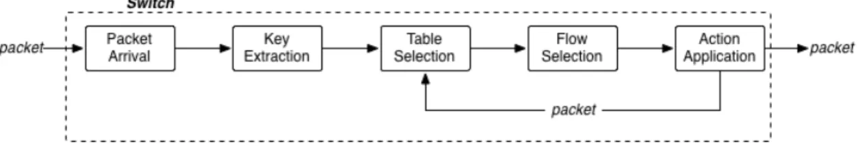
similarly as they traverse the switch data plane. Figure 1.3 shows the steps in the lifecycle of a packet.
Figure 1.3: Lifecycle of a Packet in the Switch Dataplane1
In Figure 1.3, a key is built for each incoming packet based on the information present in the packet and the metadata fields associated with it. The extracted key is used to search a table for a matching flow. In case of multiple tables, the tables are searched in an increasing order starting from the first table. On a match, the set of instructions associated with the match is executed.
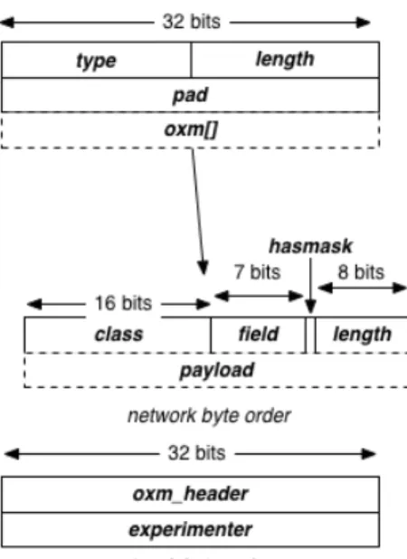
OpenFlow classifies packets using their flow signatures. These flow signatures are stored in a structure called match. Figure 1.4 shows the structure of match in OpenFlow version 1.3.1.
Figure 1.4: Structure for Match in OpenFlow 1.31
Each match structure in a flow table is associated with an instruction set. Open-Flow instructions include forwarding the packet to another table, applying a sequence of actions, etc. An action defines the policy of a flow. Some of the actions include fowarding of a packet to a specific port, enqueueing of the packet to a particular queue, stripping VLAN information of the packet, etc. A single flow can apply a sequence of actions to the same packet.
OpenFlow defines three types of messages.
1. Controller-to-switch - These messages are sent by the controller to either mod-ify a switch abstraction, or request for some information, - examples include FlowMod, GroupMod, TableMod, StatsReq, PacketOut.
2. Asynchronous - These messages are sent by the switch to either provide an information to a request or to send a packet to the controller with no matching
flow - FlowRemoved, PacketIn, StatsReply.
3. Symmetric - These messages can be sent by both controller and the switch. They are used to verify for a live connection - EchoReq/EchoRes.
Each OpenFlow message consists of a 8-byte header field. The header field (Figure 1.5) specifies the version of the OpenFlow Protocol being used, the type of message being exchanged across the management channel, thelength of the message including the header field and atransaction-id (xid) used specifically for asynchronous commu-nication. All OpenFlow versions share the same structure of the header field across all the different types of messages.
Figure 1.5: Structure for OpenFlow Header1
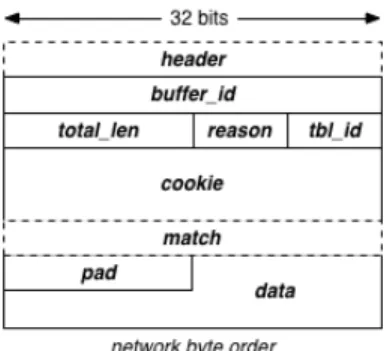
PacketIn is a common asynchronous message sent from the switch to the con-troller. It is used to send a captured packet to the controller in an event there is an unknown flow, that does not have an entry in the switch flow table. Figure 1.6 shows the structure of the message.
Figure 1.6: Message Structure for PacketIn in OpenFlow v1.31
The PacketOut message type is sent by the controller to the switch. It provides the controller the capability to inject packets into the switch dataplane. The con-troller can either inject a raw packet or indicate a local buffer from which a raw packet is released. These injected packets skip the classification stage of the data-plane and directly execute the action set provided by thePacketOut message. Figure 1.7 shows the structure of PacketOut message.
Figure 1.7: Message Structure for PacketOut in OpenFlow v1.31
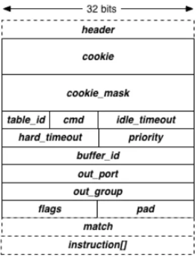
FlowMod is a message type sent by the controller to the switch to modify the state of the flow table. It is arguably the most important message in the OpenFlow
protocol, as it defines the forwarding actions of the data plane. A FlowMod message has three different commands i.e. adding, deleting or modifying a flow in a specific flow table. It contains a match to classify the flows and a sequence of instructions to describe the flow policies. Figure 1.8 shows the structure of FlowMod message.
Figure 1.8: Message Structure for FlowMod in OpenFlow v1.31
TableMod is a message type sent by the controller to the switch to configure the state of a flow table. This message defines the fate of a packet when there is a Table miss. A packet can be forwarded to the controller, dropped or sent to next table in the event of a table miss. The TableMod message structure is shown in Figure 1.9.
Figure 1.9: Message Structure for TableMod in OpenFlow v1.31
2. FLOWCACHE DESIGN
2.1 Flowcache Architecture
A standard SDN architecture consists of switches, controllers and applications. The applications run above the controllers and use the controller interface to config-ure and program the underlying switches to meet its requirements. The controller acts as a computationally heavy element of the SDN architecture. It maintains the state of the underlying network and typically uses a south bound protocol such as OpenFlow ([5],[6]) to interact with the different switches. The switches are simple networking elements which provide dataplane forwarding capabilities.
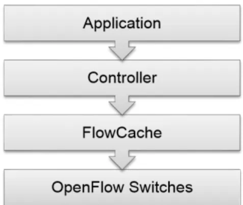
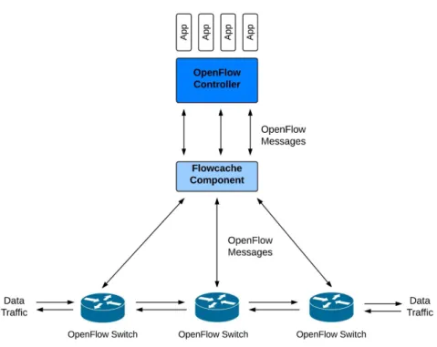
In our SDN architecture (Figure 2.2 and 2.1), we introduce a flowcache which transparently sits between the controller and the switches. It acts as a proxy device, intercepting the standard OpenFlow messages being sent across the management links (i.e., the communication links between the controller and the switches that transmit control traffic) to monitor the required behaviour of the switch.
Figure 2.2: SDN Architecture with Flowcache
The following sections provide an overview of the different properties of a flow-cache, the possible locations it can be deployed, and the way it handles the OpenFlow messages sent across the management link.
2.1.1 Flowcache Properties
Flowcacherequires a large storage capacity to exploit the concept of “unbounded” flows. It creates the same number of flow tables as in the switch, mapping each table in flowcache to a table in the switch. A flow table in flowcache constantly maintains a superset of all the flows installed in the corresponding flow table in switch. In case of a PacketIn event, flowcache searches its own flow tables for a header match. On a hit, it sends a corresponding FlowMod/PacketOut to the switch. In case of a miss, it sends a PacketIn message to the Controller.
The transparency property helps flowcache to work in the current SDN model. Neither the controller, nor the switch is aware of the presence of the flowcache compo-nent. To achieve transparency, flowcache accepts connections from the switch acting as a controller, and connects to an actual controller representing itself as a switch. This transparency property further aids in adding hierarchical levels of flowcache, as discussed in section 2.4
2.1.2 Flowcache Location
Flowcache can be deployed at four possible locations in the SDN architecture - the controller, the hardware switch, a server located in the same LAN as the hardware switch or elsewhere in the network. Each location has its own advantages and disadvantages as discussed below:
• In the Controller- Located besides the controller (Figure 2.3), the flowcache shares its burden by managing all the switches trying to connect to the con-troller. In this model, all incoming packets initially traverse through flowcache before they hit the controller. Additionally, flowcache does not require any ad-ditional hardware as it can run on the same hardware as that of the centralized controller. However, the latency across the flowcache-switch channel increases, leading to higher communication delay across the management link.
• As a Middle Box - In this model, a logically centralized controller manages switches present in multiple wide area networks (WAN). A flowcache is installed in each of these WAN’s for better management of switches. The flowcache provides faster classification of flows and reduces the communication delay across the management links. Additionally, it reduces the load on the controller by caching all similar type of flows present in a WAN like ISP flows, cable company flows, etc. However it requires an additional server to function. Figure 2.4 depicts this model.
Figure 2.4: Flowcache Location - as a Middle Box
• In Close Proximity to the Hardware Switch- In this model, a flowcache is located in close proximity to the switches (possibly on the same LAN). It manages a small number of switches leading to much faster processing of flows in the flowcache flow table. Further, as flowcache is located in close proximity to the switches, the communication delay across the flowcache-switch channel
decreases leading to better throughput of the overall system. However, this leads to an increase in the number of flowcache devices that has to be deployed in the SDN architecture, increasing the total cost of the hardware. Figure 2.5 depicts a scenario where the flowcache is located in the same LAN as the switches.
Figure 2.5: Flowcache Location - Part of LAN Connecting the Switches
• Alongside Hardware Switch - In this case the flowcache component man-ages a single switch (Figure 2.6). It is part of the switch agent which inter-acts with the controller. In this model, the communication delay across the flowcache-switch channel is minimal. Additionally, it does not require any ad-ditional hardware as it can run alongside the hardware switch. However, the communication delay across the controller-flowcache channel increases, and the performance of flowcache is limited by the switch hardware capabilities.
Figure 2.6: Flowcache Location - Switch
In our model, flowcache is located at close proximity to the OpenFlow enabled switches to minimise the communication delay across the flowcache-switch channel. The flowcache is designed with a primary focus on access networks. Access networks typically have few commodity switches connected to a master station. The master station then connects to the controller. In our design, the flowcache will be located in the master station.
2.1.3 Handling Openflow Messages
The flowcache transparently interprets all the OpenFlow messages. The Open-Flow messages can be broadly divided into three different categories.
1. Modification/Update Messages : The OpenFlow protocol supports four dif-ferent types of modification messages namely FlowMod, TableMod, GroupMod and PortMod. The FlowMod message is used to add, modify or delete flows from a spe-cific table in the switch. On receiving a FlowMod message, the flowcache initially updates its corresponding flow table. It then updates the corresponding flow table in the switch by passing the FlowMod down to the switch (Fig 2.7). The flowcache handles the overflow error condition, by evicting a flow based on the eviction pa-rameter. The GroupMod and the PortMod messages are simply redirected to the
switch. The TableMod message is used to set the table configurations of the switch. The Flowcache restricts the upper layer controller to modify the configuration state of the flow table in a switch. It updates the configuration of its own flow table to get the desired output.
Figure 2.7: Flow Modification Scenario
2. Traffic Statistics : Flowcache polls the switch for statistics of all the installed flows at fixed intervals of time. On receiving a Mutlipart StatsReq message, it queries the switch with the specific type of request. However, for a StatsReq of an inactive flow present in the flowcache, it simply responds with the statistics information main-tained in its own flow table. Figure 2.8 depicts this scenario. The dotted messages represent the query messages which may possibly be sent to the switch based on
whether the flow is currently installed in the switch.
Figure 2.8: Query Scenario
3. Synchronization Request: OpenFlow protocol makes extensive use of the Bar-rier Request and Response messages. These messages synchronize the decisions made by the controller onto the switch. On receiving a Barrier message, a switch is required to complete all the previous commands, before executing any future requests. The sequence of events that occurs on receiving a Barrier message is pictorially depicted in the Figure 2.9
Figure 2.9: Synchronization Scenario
2.2 Eviction in Switch
Flowcache acts as aninclusive cache. It buffers all the flows being installed by the controller to the hardware switch. For each such flow, it stores metadata, which helps to maintain consistency between the switch and the cache (Figure 3.2). A flow is classified as active when installed in the switch; otherwise, it is classified as dormant. Periodically, all the active flows are updated using the flow statistics obtained from the switch.
Flowcache needs to evict a flow from the switch, when the flow table is completely filled or a maximum configurable threshold has been reached. Different eviction strategies can be deployed as discussed in Section 2.2.3. However, in each such eviction strategy, flowcache needs to inspect about different types of dependencies that exists between flows. There are two separate types of dependencies that needs to be considered.
• IntraTable Dependencies - Dependencies between flows in the same table. • InterTable Dependencies - Dependencies between flows in different tables.
2.2.1 IntraTable Dependencies
A flow table consists of a cardinal number of flows which are sorted based upon priority and exact match rules. Each flow rule consists of a match structure mapped to a set of instructions. Whenever a packet matches a flow, the instruction set associated with the flow is executed. Starting version 1.3, OpenFlow allows the match structure to contain wildcard fields and arbitrary masks.. This allows the same packet to match multiple flows in the table. In such a case, the flow with the highest priority is selected.
The controller assigns the priority to flow rules, which along with the match structure decides the route a packet traverses when it hits the data plane. The flowcache may need to evict a flow from the switch periodically. However, during eviction, it must ensure that all data packets are routed through the same path irrespective of whether a flowcache is present in the SDN architecture.
For example, let us consider the flow table depicted in Table 2.1. Let the rules R1, R2,. . . ,R6 be arranged in decreasing order of priority. The set of all packets matching rule R2, also matches rule R4. In the current configuration of the flow table, when a packet with header of type 01110 arrives, rule R2 is selected based on its higher priority value. However, simply evicting rule R2 from the table, leads us to an inconsistent state. Now, the same packet would match rule R4, and would be sent across the wrong output port. These inconsistencies needs to be discovered and managed by flowcache while evicting flows from the flow table.
Table 2.1: An Example OpenFlow Flow Table Rules Match Instructions(with Actions)
R1 11110 GOTO Table 1
R2 011*0 Output Port 1
R3 111*0 GOTO Table 2
R4 0*1** Output Port 2
R5 1*1** Output Port 3
R6 All Match Drop
The paper [3] by Rexford presents an approximate solution to the above problem. In their solution, they initially construct a dependency graph, where a rule is said to be dependent on a rule of lower prioirty, if the set of packets matching the current rule also matches a lower priority rule. In our example, rule R2 is directly dependent upon rule R4. Rexford’s solution also defines indirect dependencies, i.e. say rule R3 is directly dependent on rule R5, and rule R5 is directly dependent upon rule R6, then rule R3 is also dependent upon rule R6 (the transitivity property). Figure 2.10 shows the dependency graph for table 2.1.
Figure 2.10: Intra Table Dependency Graph
Following the algorithm presented in Rexford’s paper [3], we extracted the flows from the switches in dependent cover sets. We tried to minimise the number of flows to be evicted based on the volume of traffic hitting a flow.
2.2.2 InterTable Dependencies
Starting OpenFlow protocol 1.1, an OpenFlow switch formally introduces the abstraction of multiple flow tables. It allows the controller to have fine-grained control over each flow table. Multiple flow tables simplify flow management and reduce explosion in the number of flow entries. The manual [12] by ONF presents example applications describing the use of multiple flow tables.
A packet traversing the switch dataplane initially hits the first flow table. It advances from tableito tablej, where 0≤i < j ≤n, on executing an instruction of type GOTO Table (Figure 2.11). This implies all packets hitting flow table j where i < j ≤n need to be directed to table j from a prior table.
Figure 2.11: OpenFlow Instruction Type Goto Table
On eviction of a flow entry with an instruction of type Goto Table ’T’, it is possible that an entry in the corresponding flow table ’T’ becomes stale. To illustrate the above scenario, let’s assume two OpenFlow tables in a switch say Table 0 and Table 1 (Figure 2.12). Table 0 acts as a security firewall table, where it rejects all flows not originating from IP addresses 128.0.0.1/16 and 128.0.8.1/16. It further classifies packets based on its source of origin. Table 1 acts as a QoS table. It direct packets through different output ports based on the type of service expected. By Table 1, all data packets with VLAN id “SFast” are sent through the output port 2. Now, say we decide to evict the flow entry A2. Since A2 is the only entry which sets the packet VLAN id to “SFast”, evicting it would imply none of the packets match the flow entry B2 in Table 1, i.e. the entry B2 becomes stale.
A possible solution to the above problem is to identify and evict stale entries during eviction of normal entries. To identify stale entries, we construct a reference graph. In this graph, a node represents a flow entry, whereas an edge represents a reference between two flow entries. Whenever an entry ‘E’ containing an instruction of type GOTO Table ‘T’ is inserted, we formulate the packet set ‘S’ that matches the newly inserted entry, and advances to the next table ‘T’. The packet set ’S’ is a sequence of 0,1 and wildcard bits. For all rules in table ‘T’, we find the intersection of the packet set ‘S’ and their match set. On every successful match, we add a reference edge between ’E’ and the matched rule.
We consider the second case here. On insertion of a simple flow rule, we verify if a reference edge needs to be added between a prior table rule and the new rule. For that purpose, each table keeps track of all the prior tables entries, where it has been referenced. Next, we try to find the intersection of the set of packets originating from these entries, and the newly added entry. On success, we would add a reference edge from the earlier entry to the new entry. Figure 2.13 shows the reference edges being added between flow entries.
Eviction is a comparatively simple process. On eviction of a flow, we validate the state of all the reference edge nodes. For all the nodes prior to the current table, we remove the edge. For all other nodes, we verify the incoming edge count. A NIL count indicates the node has become stale and has to be evicted out.
The above solution requires an exhaustive search of flow entries at the time of insertion of a rule. Further, the packet set S matching a flow entry can have a wide range of values, given the large number of fields OpenFlow allows a packet to be matched on.
In our implementation, we employ an easy and efficient solution. We avoid evict-ing stale entries at the time of removal of an entry, and depend on our eviction policy to handle these entries. We try to argue, that since the stale entries do not match on a data packet, the eviction strategy should evict these entries first. In this way, we deal with only current entries and reduce the total time taken during eviction.
2.2.3 Eviction Strategies
Hardware switches perform better in comparison to software switches. However, these switches are limited by hardware resources such as TCAMs, queues, buffers, etc. Managing these resources efficiently becomes necessary for improved network performance. An important and critical switch resource is a flow table. In order to efficiently manage a flow table, flows must be periodically evicted based upon various strategies.
Eviction in a flow table is a known problem. Inherently, in OpenFlow protocol, the controller can evict a flow from the switch in two ways
-1. Request of the Controller - Sending a FlowMod message of command type DELETE
However, selecting the flow to be evicted is a challenging task. Different studies have tried to address this problem based upon the application requirements and flow statistics. Broadly, eviction in a switch can be classified depending upon the locality of flows.
• Spatial Locality - In this type of locality, packets hitting a particular flow in the switch provide some indication on the type of packets that will hit the switch in the near future. Here, the locality is often dependent upon the type of application running on the controller. For example, say we have a DHCP application currently running on the controller. When the controller application receives a PacketIn message with a DHCP DISCOVER packet, it can preinstall flows on the switch based on the future expected DHCP messages like DHCP OFFER and DHCP REQUEST messages.
• Temporal Locality - This locality is based on the network load. Higher number of packets hitting a flow indicates a higher importance to that flow, while a flow with low packet hit in the recent past indicates a less important flow. This type of locality tries to extract metadata information from the frequency of data packets, rather than the type of packet. Common eviction strategies like LRU, FIFO are based on the temporal locality.
A flowcache acts as a transparent component which needs to manage the table space in a switch. It is unaware of the type of applications currently running on the controller. Thus, for eviction it relies on the temporal locality of the flows and is dependent upon the packet statistics rather than the type of packet hitting the switch. Different kind of eviction strategies can be applied to maintain the table space inside a switch. Figure 2.14 depicts a generic sequence of packet exchanges used to install a flow in a specific switch table, which is currently full.
Figure 2.14: Eviction Scenario in a Switch
In Figure 2.14, the switch initially sends a PacketIn message to flowcache. The flowcache component searches for a flow matching the packet header. On a successful hit, the flowcache would try to install the matched flow onto the switch. Since the switch table is currently full, flowcache first needs to evict a flow from the switch. After successful eviction, it installs the new flow in the switch.
In the next section, we discuss three different type of eviction strategies that can be used by flowcache.
2.2.3.1 Eviction Done by Switch
In this strategy, the switch itself can be configured to evict flows from the table. When a switch table is completely full, or a maximum threshold has been reached, the switch evicts a flow based on the type of eviction policy currently in use. Starting OpenFlow 1.4, the OpenFlow protocol allows the controller to configure the switch to evict flows either based on the importance of a flow, or based upon lifetime of a
flow. Figure 2.15 defines the structure of the message used to configure the eviction policy in switch table.
Figure 2.15: Message Structure to Configure Switch for Eviction in OpenFlow 1.4
In Figure 2.15, the TableMod message is sent across to the switch with theconfig field set as OFPTC EVICTION. The table property message type directs the switch to evict flows based on the flags specified in the flow. Table 2.2 lists the flags along with their description.
Flags Description
FLAG OTHER Evict flows based on internal switch constraints FLAG IMPORTANCE Evict flows based on their assigned importance FLAG LIFETIME Evict flows based on their remaining lifetime
Table 2.2: Flags for TableMod Eviction Property
Open-vSwitch supports OpenFlow protocol 1.4. Given the complexity of the OpenFlow protocol and its frequent iterations, it is difficult for vendors and open-source or-ganizations to maintain the most recent OpenFlow standard. Further, the current message structure, does not provide dependency management. Both inter-table and intra-table dependencies needs to be considered at the time of eviction.
2.2.3.2 Eviction using Flow Statistics
In this strategy, the flowcache evicts flows from the switch, using the mea-sure of flow statistics. OpenFlow 1.3 protocol defines messages MultipartStats Re-quest/Reply which help the controller to obtain flow statistics from the switch.
Flowcache internally maintains packet count for all flows. Periodically, it updates the count by requesting the switch for flow statistics of all the flows currently residing in the switch.
Flowcache can maintain either coarse-grained or fine-grained flow statistics. Its granularity depends upon the periodicity of the request. The periodicity itself de-pends upon the available bandwidth across the flowcache and switch channel. Al-though fine-grained statistics provide a near real-time view of specified switch table and may lead to a better eviction policy, it overloads the switch with frequent re-quests. Further, since a commodity switch can contain ∼ 2K flows, frequently obtaining the statistics of all the flows will put the available bandwidth across the control channel under pressure.
2.2.3.3 Eviction using Timeouts
In this strategy, flowcache tries to setup flows with near perfect idle and hard timeout values. A hard timeout value implies the flow entry is to be removed after the specified number of seconds, regardless of how many packets it has matched, while a idle timeout value implies the flow entry is to be removed when it has matched
no packets in the specified number of seconds. Recent studies by Zarek and Vishnoi ([17], [15]) have worked on different algorithms to predict perfect idle time timeout values.
A small timeout value leads to early eviction of a flow from the switch, increasing the PacketIn count to the controller. However, a large timeout value leads to flows being resident on the switch for a longer duration. This in turn leads to an increase in the ’working set of flows’ - the number of flows residing in the switch at the same time, thus requiring a larger switch table size. Therefore, it is critical to setup flows with near perfect timeout values. The work by Vishnoi and Zarek present heuristic based timeout values. Both their prediction algorithms, starts at a small idle timeout value for all the flows. The timeout values for frequent flows increases based upon different network heuristics like number of packetIn’s for the same flow, interval between packetIn’s for the same flow, etc. Their algorithms show around 50% improvements when compared to a standard SDN model.
However, given the advantages of their prediction techniques, it is still a complex task to not only search for near perfect timeout values, but also to maintain these values as the load on the network continuously changes. Further, the time taken for the different prediction algorithms to converge is an important factor which needs to be studied.
2.3 Transparency Property
The flowcache transparently sits between the controller and the switch. This transparency allows a flowcache to work in the current SDN model. It also enables us to insert flowcaches’ at different locations in the SDN architecture, thus allowing a model of ’Hierarchy of caches’.
can only evict flows based on temporal locality of reference, and misses on applica-tion caching. Once the controller is made aware of the flowcache, it can configure the flowcache to store flows based upon the type of application. Further advanced caching techniques like prediction caching, prefetching can be employed for better performance.
Therefore, transparency has both its own advantages and disadvantages. In the current SDN model, flowcache is installed as a transparent software component, although future extensions can be made to enable controller-aware caching of flows.
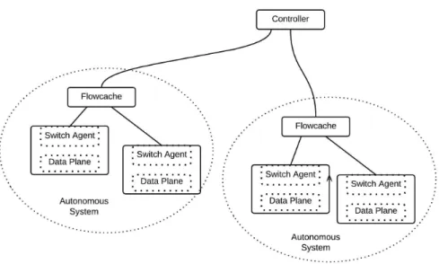
2.4 Hierarchy of Caches
A flowcache can be installed at different hierarchical levels starting from the lowest level location near the switch to the highest level near the controller. At higher levels, it is required to manage an increasing number of devices and support a larger flow-table size. The advantages and disadvantages of each location is discussed in section 2.1.2. Using this model, we can envision an SDN architecture similar to the current memory architecture, where the flowcache is installed at all hierarchical levels. Figure 2.16 depicts this architecture.
Contrary to the memory caches where the cache size increases from top to bottom, the size of flowcache grows from bottom to top. The switch itself can be compared to the smallest sized memory registers while the controller can be compared to the main memory. The flowcaches’ located at intermediate locations act as L1, L2 and L3 caches respectively as we move from the switch to the controller.
This SDN architecture gains in the advantages of the memory caches. The flow-cache located near the switch maintains a smaller flow-table, requiring less time to classify a packet. Also, the latency across the flowcache and the switch channel in-creases as we move from lower to higher levels of cache. However, this hierarchical flowcache structure has certain disadvantages with respect to networking systems. First and foremost, installing and managing different flowcaches at remote locations is costly and complex task. Second, the classification stage at each hierarchical level consumes some time, leading to an increase in latency for the first PacketIn message to the controller. Since the network traffic consists of many small flows, the time taken to route these packets increases. Therefore, this hierarchical architecture is well suited for networks with larger flows, while the increase in latency for smaller flows makes it less suitable for access networks.
3. IMPLEMENTATION
3.1 Challenges
There are a number of challenges involved in the practical implementation of flowcache. OpenFlow version 1.0, does not allow fine-grained control of flows in a switch. It allows a switch to contain multiple flow tables but does not define message structures to direct a flow to a specific table. Given the lack of control, it becomes hard for flowcache to manage space in individual tables and even more difficult to handle eviction in switches. Future versions of OpenFlow protocol allow fine-grained control of tables and flows. We implemented flowcache in OpenFlow version 1.3, the most common version used in current SDN architecture.
Transparency is an important property for flowcache to work in the current SDN architecture. However, since flowcache acts as a storage location, and does not exe-cute instructions on packets, it is unable to simply direct packets to the controlller on hitting a table-miss entry in the flowcache. Further, synchronization of addition and deletion of flows between the controller and the switch becomes a challenging task. To solve the above challenges, we exploited the use of VLAN tags´. PUSH/POP VLAN tags helped us to correctly implement the functionality of the flowcache com-ponent.
A standard switch or controller has either a north bound or a south bound con-nection interface. However, we required flowcache to work as a proxy device and thus work both as a controller and a switch at the same time. Thus it would require us to manage both the south bound and the north bound connection interfaces, for them to work in syncronization. Given the complexity of the component, we decided to build a single threaded software application. In our current implementation of
flowcache, we extended the work done by Softswitch [11], a userspace switch written in C language.
3.2 Connection Setup
Flowcacheacts as a transparent component between the switch and the controller. It accepts TCP/TLS connections from the switches identifying itself as a controller. For each accepted switch connection, it establishes a TCP/TLS connection to the controller identifying itself as a switch, with the same datapath ID.
The connection setup can be done either in a stateless or a stateful manner. In a stateless setup, the flowcache relays the messages to the controller and does not maintain the different setup states - version negotiation, feature discovery. While in a stateful setup, the flowcache maintains different connection states with both the switch and the controller. The stateless method, although easy to implement becomes difficult to manage in case of frequent disconnections. When compared to a stateless setup, a stateful setup can prevent false connections to the loaded controller.
Figure 3.1: Stateful Connection Setup in Flowcache
A flowcache does a stateful connection setup. Initially, it accepts a new OpenFlow connection request from the switch. After successful version negotiation and feature discovery states, it initiates an OpenFlow connection to the controller. Figure 3.1 illustrates the connection setup phase.
After successful connection setup phases, flowcache creates a new relay for each switch to controller connection. The next section describes the details of the relay and internal processing of flowcache.
3.3 Flowcache Internals
Flowcache maintains an internal state of all the individual flows in the switches. The table in Figure 3.2 describes the structure of a flow table inside flowcache.
Figure 3.2: A Flow Table in Flowcache
Each table coarsely contains metadata fields about the installed flow and certain packet processing fields that define the flow. The Installed field identifies all the flows presently installed in the switches. The Cookie or the Match field is used to index a flow in the specified switch. The Cookie field contains a unique value. It is set by the controller and is used extensively after the Openflow versions 1.3 to map a specific flow in the switch. The Match field is used for classification of a packet header. The eviction state parameter aids theflowcache to select a flow for eviction from the switch.
Flowcache creates a relay across the north bound and south bound interface. It filters most of the OpenFlow messages send across the channel. However, there are around nine OpenFlow messages listed in Table 3.1, which a flowcache intercepts. These intercepted messages pass through the internal flowcache state machine. De-pending upon the type of messages, they are passed through the pipeline of tables, modified, and finally passed either to the controller, or to the switch or are dropped.
Table 3.1: OpenFlow Messages Intercepted by Flowcache after Connection Setup Messages Initiated by Description
PacketIn Switch Sends captured packet to the controller PacketOut Controller Inject a packet to the switch data plane
FlowMod Controller Add/Modify/Delete a flow from the flow table FlowRemoved Switch Informs controller of a removed flow
MultipartStats Req Controller Query request for statistics MultipartStats Res Switch Query response for statistics
Barrier Req Controller Synchronization point set by controller Barrier Res Switch Synchronization request accepted by switch Error Switch Reports an error to the controller
4. EXPERIMENTAL SETUP
We constructed an experimental model to replicate the scenario of an access network. Access networks typically consists of wireless/wired access points commu-nicating to a nearby master station, which in turn communicates with the remote controller.
Figure 4.1: Experimental Setup
Our model in Figure 4.1 consisted of the Ryu [9] controller, the Userspace Softswitch [11], two Linux hosts and a flowcache component. The controller was installed on a remote machine resident on one of the rack servers. The switch and the hosts resided on a Linux machine, while the flowcache operated from a separate Linux machine connected to the same LAN. The two hosts connected to the switch via Virtual Eth-ernet pairs to form a simple linear topology. We configured the latency across the
flowcache-controller channel to be around 10ms. This configuration was based on latencies found in access networks.
Different experiments were conducted to compare the performance of the SDN model with and without flowcache. In order to test the efficiency of the system, we measured the available throughput across the two hosts. The load on the controller was measured by calculating the number of PacketIn OpenFlow messages received by the controller. Since the controller has to process each of the PacketIn message, higher number of PacketIn messages increases the load on the controller.
The workload traffic was generated using CAIDA [13] packet trace. CAIDA captures packet using passive traffic monitors located at various core routers. The packet’s were captured on a 10GB line card and had an average throughput of around 3GBps in 60 seconds window. Due to privacy reasons, the traces were anonymized, and data link-layer headers and the packet data portion were deleted.
In our experiment, we scaled down the packet trace to run with an average throughput of around 22Mbps. Since, the trace provided only layer3 and layer4 headers, we had to create our own network traffic. We installed a UDP client and a packet sniffer at two end hosts. The UDP client would send packets to the packet sniffer ip, changing the UDP destination ports to the layer 4 ports obtained from CAIDA packet trace. Using this technique we generated individual flows. In our test, we inserted around 200,000 packets in the network at an average rate of 22Mbps. These 200,000 packets resulted in generation of around 24,500 individual flows.
5. RESULTS AND DISCUSSION
We evaluated the performance of our system by measuring the throughput across the end hosts. We examined the change in throughput by varying the size of the switch flow table. In our model as shown in Figure 4.1, the latency across the flowcache-controller channel and switch-controller channel was configured as 5 ms, while the latency across switch-flowcache channel was around 0 ms. In figure 5.1, the observed throughput for flowcache remained constant for all the table sizes at the set input rate. However, the performance of the base SDN model (i.e. without flowcache) constantly decreased with smaller table sizes. In this experiment, flowcache sent around 26000 flow requests to the controller compared to around 100000 flow requests sent in the base case. The high count of flow requests in the 5 ms latency channel caused the performance decrease in the base SDN model.
In order to measure the load on the controller we count the number of PacketIn messages received by the controller. Figure 5.2 shows the difference in the number of messages processed by the controller. An increase in the size of the flow table led to higher hit rate, leading to less number of PacketIn messages being sent to the controller. The SDN model using the flowcache component sends PacketIn message only on finding a new flow. Since flowcache buffered all the flows installed by the controller, it avoided sending a request for the same packet it had encountered before. This led to smaller number of PacketIn messages to the controller, producing an almost constant load across all table sizes. The number of PacketIn messages sent across the flowcache-controller channel was considerably less when compared to the base SDN model.
Figure 5.2: Measuring the Load on Controller for Varying Flow Table Size
We compared the performance of our system using different eviction policies namely LRU, FIFO, and Statistics based. The LRU and FIFO policy are imple-mented in the software switches, while the statistics based policy is managed directly
experimental model. Clearly, the statistics based measurement performs poorly, while the LRU and FIFO schemes show similar performance. The statistics based policy required additional time for the flow statistics message to be sent across the flowcache-switch channel. Since a flow table consists of hundreds of flows, each flow statistics request placed an added pressure on the switch, decreasing the forwarding time of the switch. Further, flowcache needed to send additional flow modificiation messages to the switch to delete a flow, compared to the automatic deletion done by the switch in LRU and FIFO schemes. In Figure 5.3, we were unable to obtain the results for table size 800 in case of statistics based eviction policy, due to the limita-tions of the software switch [11]. It does not support sending statistics measurement across multiple OpenFlow messages, and the statistics measurement of a table size with 800 flows exceeds the maximum OpenFlow message length of 65535.
Here, we try to contrast the performance obtained by using statistics measure-ments at different periodicities. Coarse-grained statistics were obtained at an interval of 10 seconds, whereas fine-grained statistics were obtained at a small interval of 1 second. Fine-grained statistics presents a near real-time view of the switch, but puts additional pressure on the switch and the communication channel. In our experi-ment, the fine-grained statistics showed better performance for tables sized 400 and 200 (Figure 5.4). In these two cases, the number of PacketIn messages were compar-atively less, and evicting flows based on real time view of the tables resulted in better performance. However, for table sized 100, the state of the table changed rapidly, so in fine-grained eviction policy the additional flow statistics failed to provide real-time view of the tables and only added excess traffic to the control plane channel.
6. CONCLUSION
There are several challenges in designing a flowcache. First and foremost caching in software is slow. With OpenFlow standard introducing wider match fields, packet classification time is constantly increasing. In such a scenario, a lightly loaded con-troller may be faster to install new flows, than obtaining them from flowcache. Be-sides classifying packets, the flowcache needs to constantly estimate and maintain the “working set of flows”. Often packets arriving in bursts can lead tothrashing, causing the same packets to continuously cycle between flowcache and switch. Further, esti-mating the “working set of flows” may be a difficult task, since incoming packet rate often depends upon external conditions like time of day, date, occasion, etc. Given the above challenges faced to make flowcache work as a transparent component made the design and development cycle even more exacting.
7. FUTURE WORK
Flowcache can be extended in different directions. It can be extended to solve the compatibility issues between different OpenFlow versions. Currently, a number of OpenFlow switches support separate versions of the OpenFlow protocol. In this situation, it becomes difficult for a controller to manage these switches. An applica-tion developer is either limited by the base set of capabilities supported by all the switches, or feels the need to manage the capabilities of each switch separately. In such cases, Flowcache can present ‘a big switch’ abstraction to the controller, where it provides the controller application an interface to the most advanced set of capa-bilities supported by a switch in the given network. All capacapa-bilities not handled by a switch will be handled internally by flowcache using a software switch.
Flowcache can also extend its support for all the dataplane abstractions. Cur-rently, flowcache only supports the switch flow table abstraction. New abstractions like groups, queues and meters can be individually handled by flowcache.
Starting 2014, ONF has started to work towards OpenFlow 2.0, in an effort to increase the flexibility of the switch dataplane by making packet processors pro-grammable and protocol-independent. In this work, they define an Intermediate Representation (IR) which resides in a separate location between the switch and the controller. Given the preference of the location, flowcache can fit their model. How-ever, for flowcache to work in OpenFlow 2.0 its capabilities must be modified and extended to meet their specific requirements.
REFERENCES
[1] Flowgrammable - OpenFlow protocol description. Retrieved February 5, 2015 from http://flowgrammable.org.
[2] Soheil Hassas Yeganeh and Yashar Ganjali. Kandoo: A framework for efficient and scalable offloading of control applications. InProceedings of the First Work-shop on Hot Topics in Software Defined Networks, HotSDN ’12, pages 19–24, New York, NY, USA, 2012. ACM.
[3] Naga Katta, Omid Alipourfard, Jennifer Rexford, and David Walker. Infinite cacheflow in software-defined networks. In Proceedings of the Third Workshop on Hot Topics in Software Defined Networking, HotSDN ’14, pages 175–180, New York, NY, USA, 2014. ACM.
[4] Teemu Koponen, Martin Casado, Natasha Gude, Jeremy Stribling, Leon Poutievski, Min Zhu, Rajiv Ramanathan, Yuichiro Iwata, Hiroaki Inoue, Takayuki Hama, et al. Onix: A distributed control platform for large-scale production networks. In OSDI, volume 10, pages 1–6, 2010.
[5] Nick McKeown, Tom Anderson, Hari Balakrishnan, Guru Parulkar, Larry Peter-son, Jennifer Rexford, Scott Shenker, and Jonathan Turner. Openflow: enabling innovation in campus networks. ACM SIGCOMM Computer Communication Review, 38(2):69–74, 2008.
[6] Openflow Switch Specification - Version 1.3.0 ( Wire Protocol 0x04 ). Re-trieved April 26, 2015 from https://www.opennetworking.org/images/ stories/downloads/sdn-resources/onf-specifications/openflow/
[7] Justin Pettit, Ben Pfaff, Chris Wright, and Madhu Venugopal. The rise of soft switching, 2011. Retrieved February 5, 2015 fromhttp://networkheresy.com/ category/open-vswitch/.
[8] Ben Pfaff, Justin Pettit, Keith Amidon, Martin Casado, Teemu Koponen, and Scott Shenker. Extending networking into the virtualization layer. In Hotnets, 2009.
[9] Ryu - SDN Framework. Retrieved March 20, 2015 fromhttp://osrg.github. io/ryu.
[10] Seungwon Shin, Vinod Yegneswaran, Phillip Porras, and Guofei Gu. Avant-guard: Scalable and vigilant switch flow management in software-defined net-works. In Proceedings of the 2013 ACM SIGSAC conference on Computer & communications security, pages 413–424. ACM, 2013.
[11] Soft Switch. Retrieved March 20, 2015 from https://github.com/CPqD/ ofsoftswitch13.
[12] The Benefits of Multiple Flow Tables and TTPs. Retrieved April 26, 2015 from https://www.opennetworking.org/images/stories/downloads/ sdn-resources/technical-reports/TR_Multiple_Flow_Tables_and_TTPs. pdf.
[13] The Caida UCSD anonymized internet traces 2014. Retrieved March 20, 2015 from http://www.caida.org/data/passive/passive_2014_dataset.xml/. [14] Amin Tootoonchian and Yashar Ganjali. Hyperflow: A distributed control plane
for openflow. In Proceedings of the 2010 internet network management confer-ence on Research on enterprise networking, pages 3–3. USENIX Association, 2010.
[15] Anilkumar Vishnoi, Rishabh Poddar, Vijay Mann, and Suparna Bhattacharya. Effective switch memory management in openflow networks. In Proceedings of the 8th ACM International Conference on Distributed Event-Based Systems, DEBS ’14, pages 177–188, New York, NY, USA, 2014. ACM.
[16] Minlan Yu, Jennifer Rexford, Michael J. Freedman, and Jia Wang. Scalable flow-based networking with difane. InProceedings of the ACM SIGCOMM 2010 Conference, SIGCOMM ’10, pages 351–362, New York, NY, USA, 2010. ACM. [17] Adam Zarek, Y Ganjali, and D Lie. Openflow timeouts demystified. Univ. of