Faculty and Researcher Publications Faculty and Researcher Publications Collection
2016
Hadoop MapReduce for Mobile Clouds
George, Johnu
2168-7161 (c) 2016 IEEE. Personal use is permitted, but republication/redistribution requires IEEE permission. See http://www.ieee.org/publications_standards/publications/rights/index.html for more
Hadoop MapReduce for Mobile Clouds
Johnu George, Chien-An Chen, Radu Stoleru,
Member, IEEE,
Geoffrey G. Xie
Member, IEEE
Abstract—The new generations of mobile devices have high processing power and storage, but they lag behind in terms of software systems for big data storage and processing. Hadoop is a scalable platform that provides distributed storage and computational capabilities on clusters of commodity hardware. Building Hadoop on a mobile network enables the devices to run data intensive computing applications without direct knowledge of underlying distributed systems complexities. However, these applications have severe energy and reliability constraints (e.g., caused by unexpected device failures or topology changes in a dynamic network). As mobile devices are more susceptible to unauthorized access, when compared to traditional servers, security is also a concern for sensitive data. Hence, it is paramount to consider reliability, energy efficiency and security for such applications. The MDFS (Mobile Distributed File System) [1] addresses these issues for big data processing in mobile clouds. We have developed the Hadoop MapReduce framework over MDFS and have studied its performance by varying input workloads in a real heterogeneous mobile cluster. Our evaluation shows that the implementation addresses all constraints in processing large amounts of data in mobile clouds. Thus, our system is a viable solution to meet the growing demands of data processing in a mobile environment.Index Terms—Mobile Computing, Hadoop MapReduce, Cloud Computing, Mobile Cloud, Energy-Efficient Computing, Fault-Tolerant Computing
✦
1
Introduction
W
ith advances in technology, mobile devices areslowly replacing traditional personal computers. The new generations of mobile devices are power-ful with gigabytes of memory and multi-core proces-sors. These devices have high-end computing hardware and complex software applications that generate large amounts of data on the order of hundreds of megabytes. This data can range from application raw data to im-ages, audio, video or text files. With the rapid increase in the number of mobile devices, big data processing on mobile devices has become a key emerging necessity for providing capabilities similar to those provided by traditional servers [2].
Current mobile applications that perform massive computing tasks (big data processing) offload data and tasks to data centers or powerful servers in the cloud [3]. There are several cloud services that offer computing infrastructure to end users for processing large datasets. Hadoop MapReduce is a popular open source program-ming framework for cloud computing [4]. The frame-work splits the user job into smaller tasks and runs these tasks in parallel on different nodes, thus reducing the overall execution time when compared with a sequential execution on a single node. This architecture however,
• Johnu George, Chien-An Chen, and Radu Stoleru are with
Department of Computer Science and Engineering, Texas A&M University, College Station, TX 77840.
E-mail:{stoleru,jaychen}@cse.tamu.edu,
• Geoffrey G. Xie is with Department of Computer Science,
Naval Post Graduate School, Monterey, CA 93943 E-mail:[email protected]
Manuscript received 29 Aug. 2013; revised 24 Jan. 2014; revised 28 Mar. 2014
fails in the absence of external network connectivity, as it is the case in military or disaster response oper-ations. This architecture is also avoided in emergency response scenarios where there is limited connectivity to cloud, leading to expensive data upload and download operations. In such situations, wireless mobile ad-hoc networks are typically deployed [5]. The limitations of the traditional cloud computing motivate us to study the data processing problem in an infrastructureless and mobile environment in which the internet is unavailable and all jobs are performed on mobile devices. We assume that mobile devices in the vicinity are willing to share each other’s computational resources.
There are many challenges in bringing big data ca-pabilities to the mobile environment: a) mobile devices are resource-constrained in terms of memory, process-ing power and energy. Since most mobile devices are battery powered, energy consumption during job exe-cution must be minimized. Overall energy consumption depends on the nodes selected for the job execution. The nodes have to be selected based on each node’s remaining energy, job retrieval time, and energy profile. As the jobs are retrieved wirelessly, shorter job retrieval time indicates lower transmission energy and shorter job completion time. Compared to the traditional cloud computing, transmission time is the bottleneck for the job makespan and wireless transmission is the major source of the energy consumption; b) reliability of data is a major challenge in dynamic networks with unpre-dictable topology changes. Connection failures could cause mobile devices to go out of the network reach after limited participation. Device failures may also happen due to energy depletion or application specific failures. Hence, a reliability model stronger than those used by traditional static networks is essential; c) security is
2168-7161 (c) 2016 IEEE. Personal use is permitted, but republication/redistribution requires IEEE permission. See http://www.ieee.org/publications_standards/publications/rights/index.html for more
also a major concern as the stored data often contains sensitive user information [6] [7]. Traditional security mechanisms tailored for static networks are inadequate for dynamic networks. Devices can be captured by unauthorized users and data can be compromised easily if necessary security measures are not provided. To ad-dress the aforementioned issues of energy efficiency, reli-ability and security of dynamic network topologies, the
k-out-of-ncomputing framework was introduced [8] [9].
An overview of the previous MDFS will be described
in section 2.2. What remains as an open challenge is
to bring the cloud computing framework to ak-out-of-n
environmentsuch that it solves the bottlenecks involved in processing and storage of big data in a mobile cloud. The Hadoop MapReduce cloud computing framework meets our processing requirements for several reasons: 1) in the MapReduce framework, as the tasks are run in parallel, no single mobile device becomes a bottle-neck for overall system performance; 2) the MapReduce framework handles resource management, task schedul-ing and task execution in an efficient fault tolerant manner. It also considers the available disk space and memory of each node before tasks are assigned to any node; 3) Hadoop MapReduce has been extensively tested and used by large number of organizations for big data processing over many years. However, the default file system of Hadoop, HDFS (Hadoop Dis-tributed File System) [10] is tuned for static networks and is unsuitable for mobile environments. HDFS is not suitable for dynamic network topologies because: 1) it ignores energy efficiency. Mobile devices have limited battery power and can easily fail due to energy depletion; 2) HDFS needs better reliability schemes for data in the mobile environment. In HDFS, each file block is replicated to multiple devices considering heavy I/O bound jobs with strong requirements on backend network connections. Instead, we need lightweight pro-cesses which react well to slow and varying network
connections. Consequently, we considered k-out-of-n
based MDFS [8], instead of HDFS, as our underlying file system for the MapReduce framework.
In this paper, we implement Hadoop MapReduce framework over MDFS and evaluate its performance on a general heterogeneous cluster of devices. We im-plement the generic file system interface of Hadoop for MDFS which makes our system interoperable with other Hadoop frameworks like HBase. There are no changes required for existing HDFS applications to be deployed over MDFS. To the best of our knowledge, this is the first work to bring Hadoop MapReduce framework for mobile cloud that truly addresses the challenges of the dynamic network environment. Our system provides a distributed computing model for pro-cessing of large datasets in mobile environment while ensuring strong guarantees for energy efficiency, data reliability and security.
2
Related Work & Background
There have been several research studies that at-tempted to bring MapReduce framework to the het-erogeneous cluster of devices, due to its simplicity and powerful abstractions [11].
Marinelli [12] introduced the Hadoop based platform Hyrax for cloud computing on smartphones. Hadoop TaskTracker and DataNode processes were ported on Android mobile phones, while a single instance of NameNode and JobTracker were run in a traditional server. Porting Hadoop processes directly onto mobile devices doesn’t mitigate the problems faced in the mo-bile environment. As presented earlier, HDFS is not well suited for dynamic network scenarios. There is a need for a more lightweight file system which can adequately address dynamic network topology concerns. Another MapReduce framework based on Python, Misco [13] was implemented on Nokia mobile phones. It has a similar server-client model where the server keeps track of various user jobs and assigns them to workers on demand. Yet another server-client model based MapRe-duce system was proposed over a cluster of mobile devices [14] where the mobile client implements MapRe-duce logic to retrieve work and proMapRe-duce results from the master node. The above solutions, however, do not solve the issues involved in data storage and processing of large datasets in the dynamic network.
P2P-MapReduce [15] describes a prototype imple-mentation of a MapReduce framework which uses a peer-to-peer model for parallel data processing in dy-namic cloud topologies. It describes mechanisms for managing node and job failures in a decentralized man-ner.
The previous research focused only on the parallel processing of tasks on mobile devices using the MapRe-duce framework without addressing the real challenges that occur when these devices are deployed in the mobile environment. Huchton et al. [1] proposed a k-Resilient Mobile Distributed File System (MDFS) for mobile devices targeted primarily for military opera-tions. Chen et al. [16] proposed a new resource
al-location scheme based on k-out-of-n framework and
implemented a more reliable and energy efficient Mobile Distributed File System for Mobile Ad Hoc Networks (MANETs) with significant improvements in energy consumption over the traditional MDFS architecture.
In the remaining part of this section we present background material on Hadoop and MDFS.
2.1 Hadoop Overview
The two primary components of Apache Hadoop are the MapReduce framework and HDFS, as shown in Figure 1. MapReduce is a scalable parallel processing framework that runs on HDFS. It refers to two distinct
tasks that Hadoop jobs perform- the Map Task and
theReduce Task. The Map Task takes the input data
2168-7161 (c) 2016 IEEE. Personal use is permitted, but republication/redistribution requires IEEE permission. See http://www.ieee.org/publications_standards/publications/rights/index.html for more MapReduce Program Job Client Submit Job Hadoop JobTracker HDFS Client Name Node File.txt Block A Block B Hadoop TaskTracker HDFS Client Data Node A M R Client Node Metadata
Operations Data Read/Write Network M R A B Map Task Reduce Task File Blocks Block A Datanodes 1,2 Block B Datanodes 1,2 Hadoop TaskTracker HDFS Client Data Node M R B A B Data Read/ Write Assign Task 2 Assign Task 1
Fig. 1. Hadoop architecture
pairs which are sorted and partitioned per reducer. The map output is then passed to Reducers to produce the final output. The user applications implement mapper and reducer interfaces to provide the map and reduce functions. In the MapReduce framework, computation is always moved closer to nodes where data is located, instead of moving data to the compute node. In the ideal case, the compute node is also the storage node minimizing the network congestion and thereby maxi-mizing the overall throughput.
Two important modules in MapReduce are the
JobTracker and the TaskTracker. JobTracker is the MapReduce master daemon that accepts the user jobs and splits them into multiple tasks. It then assigns these tasks to MapReduce slave nodes in the cluster called the TaskTrackers. TaskTrackers are the process-ing nodes in the cluster that run the tasks- Map and Reduce. The JobTracker is responsible for scheduling tasks on the TaskTrackers and re-executing the failed tasks. TaskTrackers report to JobTracker at regular intervals through heartbeat messages which carry the information regarding the status of running tasks and the number of available slots.
HDFS is a reliable, fault tolerant distributed file system designed to store very large datasets. Its key features include load balancing for maximum efficiency, configurable block replication strategies for data protec-tion, recovery mechanisms for fault tolerance and auto scalability. In HDFS, each file is split into blocks and each block is replicated to several devices across the cluster.
The two modules in HDFS layer areNameNode and
DataNode. NameNode is the file system master daemon that holds the metadata information about the stored files. It stores the inode records of files and directories which contain various attributes like name, size, per-missions and last modified time. DataNodes are the file system slave nodes which are the storage nodes in the cluster. They store the file blocks and serve read/write requests from the client. The NameNode maps a file to the list of its blocks and the blocks to the list of DataN-odes that store them. DataNDataN-odes report to NameNode
Plain File
Encrypted
Encrypted AES
AES Erasure Coding Secret Sharing
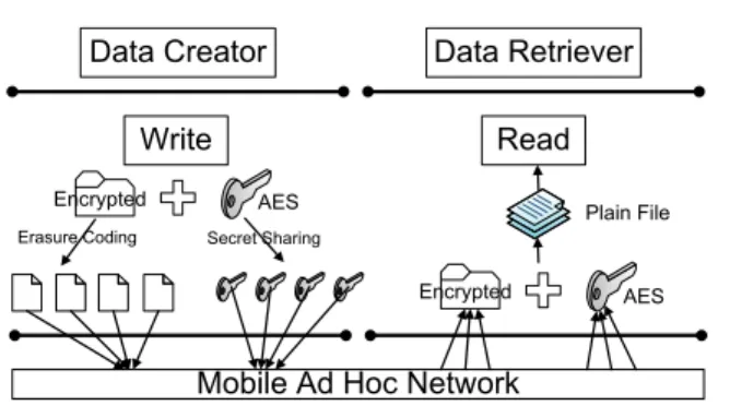
Fig. 2. Existing MDFS architecture
at regular intervals through heartbeat messages which contain the information regarding their stored blocks. NameNode builds its metadata from these block reports and always stays in sync with the DataNodes in the cluster.
When the HDFS client initiates the file read opera-tion, it fetches the list of blocks and their corresponding DataNode locations from NameNode. The locations are ordered by their distance from the reader. It then tries to read the content of the block directly from the first location. If this read operation fails, it chooses the next location in the sequence. As the client retrieves data directly from the DataNodes, the network traffic is distributed across all the DataNodes in the HDFS cluster.
When the HDFS client is writing data to a file, it initiates a pipelined write to a list of DataNodes which are retrieved from the NameNode. The NameNode chooses the list of DataNodes based on the pluggable block placement strategy. Each DataNode receives data from its predecessor in the pipeline and forwards it to its successor. The DataNodes report to the NameNode once the block is received.
2.2 MDFS Overview
The traditional MDFS was primarily targeted for mil-itary operations where front line troops are provided with mobile devices. A collection of mobile devices form a mobile ad-hoc network where each node can enter or move out of the network freely. MDFS is
built on ak-out-of-nframework which provides strong
guarantees for data security and reliability.k-out-of-n
enabled MDFS finds n storage nodes such that total
expected transmission cost to k closest storage nodes
is minimal. Instead of relying on conventional schemes which encrypt the stored data per device, MDFS uses a group secret sharing scheme.
As shown in Figure 2, every file is encrypted using
a secret key and partitioned into n1 file fragments
using erasure encoding (Reed Solomon algorithm). Un-like conventional schemes, the secret key is not stored
locally. The key is split inton2fragments using Shamir’s
secret key sharing algorithm. File creation is complete when all the key and file fragments are distributed across the cluster. For file retrieval, a node has to
2168-7161 (c) 2016 IEEE. Personal use is permitted, but republication/redistribution requires IEEE permission. See http://www.ieee.org/publications_standards/publications/rights/index.html for more
retrieve at least k1 (<n1) file fragments and k2 (<n2)
key fragments to reconstruct the original file.
MDFS architecture provides high security by en-suring that data cannot be decrypted unless an
au-thorized user obtains k2 distinct key fragments. It
also ensures resiliency by allowing the authorized users
to reconstruct the data even after losing n1-k1
frag-ments of data. Reliability of the file increases when
the ratio k1/n1 decreases, but it also incurs higher
data redundancy. The data fragments are placed on a set of selected storage nodes considering each node’s failure probability and its distance to the potential clients. A node’s failure probability is estimated based on the remaining energy, network connectivity, and application-dependent factors. Data fragments are then allocated to the network such that the expected data transferring energy for all clients to retrieve/recover the file is minimized.
MDFS has a fully distributed directory service in which each device maintains information regarding the list of available files and their corresponding key and file fragments. Each node in the network periodically synchronizes the directory with other nodes ensuring that the directories of all devices are always updated.
3
Challenges
This section describes the challenges involved in the implementation of MapReduce framework over MDFS. 1. Traditional MDFS architecture only supports a flat hierarchy. All files are stored at the same level in the file system without the use of folders or directories. But the MapReduce framework relies on fully qualified path names for all operations. The fully qualified path is added to MDFS, as described in Section 4.4.6.
2. The capabilities of traditional MDFS are very limited. It supports only a few functionalities such as read(), write() and list(). A user calls the write() function to store a file across the nodes in the network and the read() function to read the contents of a file from the network. The list() function provides the full listing of the available files in the network.
However, MapReduce framework needs a fairly generic file system that implements wide range of func-tions. It has to be compatible with available HDFS applications without any code modification or extra configuration. The implementation detail is described in Section 4.4.
3. MapReduce framework needs streaming access to their data, but MDFS reads and writes are not streaming operations. How the data is streamed during read/write operations are described in Section 4.4.
4. During the job initialization phase of Hadoop, JobTracker queries the NameNode to retrieve the in-formation of all the blocks of the input file (blocks and list of DataNodes that store them) for selecting the best nodes for task execution. JobTracker prioritizes data locality for TaskTracker selection. It first looks for
an empty slot on any node that contains the block. If no slots are available, it looks for an empty slot on a different node but in the same rack. In MDFS, as no node in the network has a complete block for processing, the challenge is to determine the best locations for each task execution. Section 4.5 proposes an energy-aware scheduling algorithm that overrides the default one.
5. The MapReduce and HDFS components arerack
aware. They use network topology for obtaining the rack awareness knowledge. As discussed, if the node that contains the block is not available for task exe-cution, the default task scheduling algorithm selects a different node in the same rack using the rack awareness knowledge. This scheme leverages the single hop and high bandwidth of in-rack switching. The challenge is
to define rack awareness in context of mobile ad-hoc
network as the topology is likely to change at any time during the job execution. This challenge is also addressed by the new scheduling algorithm described in Section 4.5.
4
System Design
In this section, we present the details of our proposed architectures, system components and the interactions among the components that occur during file system operations.
4.1 Requirements
For the design of our system, the following requirements had to be met:
• Since the Hadoop JobTracker is a single entity
common to all nodes across the cluster, there should be at least one node in the cluster which always operates within the network range and remains alive throughout the job execution phase. The system must tolerate node failures.
• Data stored across the cluster may be sensitive.
Unauthorized access to sensitive information must be prohibited.
• The system is tuned and designed for handling
large amounts of data in the order of hundreds of megabytes, but it must also support small files.
• Though we primarily focus on mobile devices,
the system must support heterogeneous cluster of devices which can be a combination of tradi-tional personal computers, servers, laptops, mobile phones and tablets depending on the working en-vironment of the user.
• Like HDFS, the system must support sequential
writes. Bytes written by a client may not be visible immediately to other clients in the network unless
the file is closed or flush operation is called.Append
mode must be supported to append the data to an already existing file. Flush operation guarantees that bytes up to that given point in the stream are persisted and changes are visible to all other clients in the system.
2168-7161 (c) 2016 IEEE. Personal use is permitted, but republication/redistribution requires IEEE permission. See http://www.ieee.org/publications_standards/publications/rights/index.html for more
• Like HDFS, the system must support streaming
reads. It must also support random reads where a user reads bytes starting from an arbitrary offset in the file.
4.2 System Components
In the traditional MDFS architecture, a file to be stored
is encrypted and split intonfragments such that anyk
(<n) fragments are sufficient to reconstruct the original file. In this architecture, parallel file processing is not possible as even a single byte of the file cannot be read without retrieving the required number of frag-ments. Moreover, MapReduce framework assumes that the input file is split into blocks which are distributed across the cluster. Hence, we propose the notion of blocks, which was missing in the traditional MDFS architecture. In our approach, the files are split into blocks based on the block size. These blocks are then split into fragments that are stored across the cluster. Each block is a normal Unix file with configurable block size. Block size has a direct impact on performance as it affects the read and write sizes.
The file system functionality of each cluster node is split across three layers- MDFS Client, Data processing layer and Network communication layer.
4.2.1 MDFS Client
User applications invoke file system operations using the MDFS client, a built-in library that implements the MDFS file system interface. The MDFS client provides file system abstraction to upper layers. The user does not need to be aware of file metadata or the storage locations of file fragments. Instead, the user references each file by paths in the namespace using the MDFS client. Files and directories can be created, deleted, moved and renamed like in traditional file systems. All file system commands take path arguments in URI format (scheme://authority/path). The scheme decides the file system to be instantiated. For MDFS, the scheme is mdfs and the authority is the Name Server address.
4.2.2 Data processing layer
Data Processing layer manages the data and control flow of file system operations. The functionality of this
layer is split across two daemons- Name Server and
Data Server.
4.2.2.1 Name Server: MDFS Name Server is a lightweight MDFS daemon that stores the hierarchical file organization or the namespace of the file system. All file system metadata including the mapping of a file to its list of blocks is also stored in the MDFS Name Server. The Name Server has the same functionality as Hadoop NameNode. The Name Server is always up-dated with any change in the file system namespace. On startup, it starts a global RPC server at a port defined by mdfs.nameservice.rpc-port in the configuration file.
The client connects to the RPC server and talks to it using the MDFS Name Protocol. The MDFS client and MDFS Name Server are completely unaware of the fragment distribution which is handled by the Data Server. We kept the namespace management and data management totally independent for better scalability and design simplicity.
4.2.2.2 Data Server: The MDFS Data Server is a lightweight MDFS daemon instantiated on each node in the cluster. It coordinates with other MDFS Data Server daemons to handle MDFS communication tasks like neighbor discovery, file creation, file retrieval and file deletion. On startup, it starts a local RPC server listening on the port defined by mdfs.dataservice.rpc-port in the configuration file. When the user invokes any file system operation, the MDFS client connects to the local Data Server at the specified port and talks to it using the MDFS Data Protocol. Unlike Hadoop DataNode, the Data Server has to be instantiated on all nodes in the network where data flow operations (reads and writes) are invoked. This is because the Data Server prepares the data for these operations and they are always executed in the local file system of the client. The architecture is explained in detail in the subsequent sections.
4.2.3 Network communication layer
This layer handles the communication between the nodes in the network. It exchanges control and data packets for various file operations. This layer abstracts the network interactions and hides the complexities involved in routing packets to various nodes in case of dynamic topologies like in MANETs.
4.2.3.1 Fragment Mapper: The Fragment Map-per stores information of file and key fragments which include the fragment identifiers and the location of fragments. It stores the mapping of a block to its list of key and file fragments.
4.2.3.2 Communication Server: The Communi-cation Server interacts with every other node and is responsible for energy-efficient packets routing. It must support broadcast and unicast, the two basic com-munication modes required by MDFS. To allow more flexible routing mechanisms in different environments, it is implemented as a pluggable component which can be extended to support multiple routing protocols.
4.2.3.3 Topology Discovery & Maintenance
Framework: This component stores the network
topology information and the failure probabilities of participating nodes. When the network topology changes, this framework detects the change through a distributed topology monitoring algorithm and updates the Fragment Mapper. All the nodes in the network are thus promptly updated about network topology changes.
There are two types of system metadata. The file
system namespace which includes the mapping of file
2168-7161 (c) 2016 IEEE. Personal use is permitted, but republication/redistribution requires IEEE permission. See http://www.ieee.org/publications_standards/publications/rights/index.html for more Submit Job MapReduce Program Job Client Hadoop JobTracker MDFS Client Commun. Server Fragment Mapper Block 1 Frag A Frag B Block 2 Frag C Frag D Name Server File.txt Block 1 Block 2 Data Server A C Hadoop TaskTracker MDFS Client Commun. Server M R Client Node Assign Task Metadata
Operations Data Read/Write Data Read/Write
Network
Fragment Mapper Block 1 Frag A Frag B Block 2 Frag C Frag D Data Server B D Metadata Operations M R A B C D Map Task Reduce Task File Fragments Fragment
Operations OperationsFragment
Name Server File.txt
Block 1 Block 2
Fig. 3. Distributed Architecture of MDFS
block to fragmentsis stored in the Fragment Mapper. It was our design decision to separate Fragment Mapper functionality from the Name Server. There are two reasons 1) The memory usage of Fragment Mapper can
grow tremendously based on the configured value of n
for each file. For example, consider a system withnset
to 10. For a 1 MB file with 4MB block size, only one
block is required but 10 fragments are created byk
-out-of-n framework. Hence, there are 10 fragment entries
in the Fragment Mapper and only 1 block entry in the Name Server for this particular file. Since memory requirements of Name Server and Fragment Mapper are different, this design gives flexibility to run them independently in different modes. 2) Fragment Mapper is invoked only during network operations (read/writes) while the Name Server is accessed for every file system operation. Since the Name Server is a light weight daemon that handles only the file system namespace, the directory operations are fast.
4.3 System Architecture
We propose two approaches for our MDFS architecture-a Distributed architecture where there is no central
entity to manage the cluster and aMaster-slave
archi-tecture, as in HDFS. Although the tradeoffs between the distributed architecture and the centralized archi-tecture in a distributed system are well-studied, this paper is the first to implement and compare Hadoop framework on these two architectures. Some interesting observations are also discovered, as described in sec-tion 6.6. The user can configure the architecture during the cluster startup based on the working environment. It has to be configured during the cluster startup and cannot be changed later.
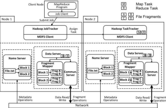
4.3.1 Distributed Architecture
In this architecture, depicted in Figure 3, every par-ticipating node runs a Name Server and a Fragment Mapper. After every file system operation, the update is broadcasted in the network so that the local caches of all nodes are synchronized. Moreover, each node pe-riodically syncs with other nodes by sending broadcast
messages. Any new node entering the network receives these broadcast messages and creates a local cache for further operations. In the hardware implementation, the updates are broadcasted using UDP packets. We assume all functional nodes can successfully receive the broadcast messages. The more comprehensive and robust distributed directory service is left as future work.
This architecture has no single point of failure and no constraint is imposed on the network topology. Each node can operate independently, as each node stores a separate copy of the namespace and fragment map-ping. The load is evenly distributed across the cluster in terms of metadata storage when compared to the centralized architecture. However, network bandwidth is wasted due to the messages broadcast by each node for updating the local cache of every other node in the network. As the number of nodes involved in processing increases, this problem becomes more severe, leading to higher response time for each user operation.
4.3.2 Master-Slave Architecture
In this architecture depicted in Figure 4, the Name Server and the Fragment Mapper are singleton in-stances across the complete cluster. These daemons can be run in any of the nodes in the cluster. The node that runs these daemons is called the master node. MDFS stores metadata on the master node similar to other distributed systems like HDFS, GFS [17] and PVFS [18].
The centralized architecture has many advantages. 1) Since a single node in the cluster stores the complete metadata, there is no wastage of the device memory by storing same metadata in all nodes when compared to the distributed approach. 2) When a file is created, modified or deleted, there is no need to broadcast any message across the network to inform other nodes for updating their metadata. This saves overall network bandwidth and reduces transmission cost. Lesser trans-mission cost leads to higher energy efficiency of the sys-tem. 3) Since our system is assumed to have at least one node that always operates within the network range, the Name Server and the Fragment Mapper can be run in the same node that hosts the Hadoop JobTracker. It can be a static server or any participating mobile device. Thus this approach doesn’t violate any of our initial assumptions.
The major disadvantage of the centralized approach is that the master node is a single point of failure. However, this problem can be solved by configuring a standby node in the configuration file. The standby node is updated by the master node whenever there is a change in the file system metadata. The master node signals success to client operations only when metadata change is reflected in both master and standby nodes. Hence, data structures of the master and standby node always remain in sync ensuring smooth failover.
2168-7161 (c) 2016 IEEE. Personal use is permitted, but republication/redistribution requires IEEE permission. See http://www.ieee.org/publications_standards/publications/rights/index.html for more MapReduce Program Job Client Submit Job Hadoop JobTracker MDFS Client Commun. Server Fragment Mapper Block 1 Frag A, Frag B Block 2 Frag C, Frag D Data Server A C Hadoop TaskTracker MDFS Client Commun. Server Data Server B D M R Client Node Assign Task Metadata
Operations Data Read/Write
Data Read/ Write Network M R A B C D Map Task Reduce Task File Fragments Fragment Operations Name Server File.txt Block 1 Block 2
Fig. 4. Centralized Architecture of MDFS
MDFS CLient Name Server Data Server File Retrieval Module Commu. Server Fragment Mapper k-out-of-n framework 1 2 3 20 4 5 19 8 11 6 7 Topology Discovery/ Maintenance Unit 12 15 MDFS Client Data Server Commu. Server 9 10 MDFS Client Data Server Commu. Server 13 14 16-18 Control Flow Data Flow
Fig. 5. Data Flow of a read operation
The master node can be loaded when large number of mobile devices are involved in processing. There are sev-eral distributed systems like Ceph [19] and Lustre [20] that support more than one instance of metadata server for managing the file system metadata evenly. Multi-ple metadata servers are deployed to avoid scalability bottlenecks of a single metadata server. MDFS can now efficiently handle hundreds of megabytes with a single metadata server and there is no need for multiple metadata servers in our environment. For rest of the discussion, we use centralized approach for simplicity.
4.4 System Operations
This section describes how the file read, file write, file append, file delete, file rename, and directory operations are performed in a centralized architecture.
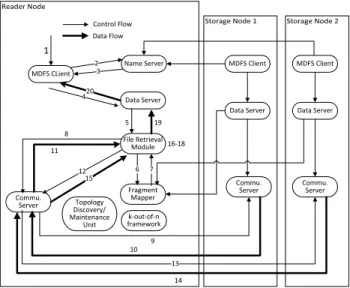
4.4.1 File Read Operation
HDFS read design is not applicable in MDFS. For any block read operation, the required number of fragments has to be retrieved and then combined and decrypted to recover the original block. Unlike HDFS, an MDFS block read operation is always local to the reader as
the block to be read is first reconstructed locally. For security purpose, the retrieved key/data fragments and the decoded blocks are deleted as soon as the plain data is loaded into the taskTracker’s memory. Although there is a short period of time that a plain data block may be compromised, we leave the more secure data processing problem as future work.
The overall transmission cost during the read opera-tion varies across nodes based on the locaopera-tion of frag-ments and the reader location. As the read operation is handled locally, random reads are supported in MDFS where the user can seek to any position in the file. Figure 5 illustrates the control flow of a read operation through these numbered steps.
Step 1:The user issues a read request for file blocks
of lengthLat a byte offset O.
Steps 2-3:As in HDFS, the MDFS client queries the
Name Server to return all blocks of the file that span
the byte offset range fromOtoO+L. The Name Server
searches the local cache for the mapping from the file to the list of blocks. It returns the list of blocks that contain the requested bytes.
Step 4: For each block in the list returned by the
Name Server, the client issues a retrieval request to the Data Server. Each file system operation is identified by a specific opcode in the request.
Step 5: The Data Server identifies the opcode and
instantiates the File Retriever module to handle the block retrieval.
Steps 6-7: The Data Server requests the Fragment
Mapper to provide information regarding the key and file fragments of the file. The Fragment Mapper replies with the identity of the fragments and the locations of the fragments in the networks.
Steps 8-15:The Data Server requests the
Communi-cation Server to fetch the required number of fragments from the locations which are previously returned by the Fragment Mapper. Fragments are fetched in parallel and stored in the local file system of the requesting client. After fetching each request, the Communication Server acknowledges the Data Server with the location where the fragments are stored in the local file system.
Step 16: The above operations are repeated for
fetching the key fragments. These details are not in-cluded in the diagram for brevity. The secret key is constructed from the key fragments.
Step 17:Once the required file fragments are
down-loaded into the local file system, they are decoded and then decrypted using the secret key to get the original block.
Step 18: The key and file fragments which were
downloaded into the local file system during the re-trieval process are deleted for security reasons.
Step 19: The Data Server acknowledges the client
with the location of the block in the local file system.
Step 20: The MDFS client reads the requested
number of bytes of the block. Steps 4-19 are repeated if there are multiple blocks to be read. Once the read
2168-7161 (c) 2016 IEEE. Personal use is permitted, but republication/redistribution requires IEEE permission. See http://www.ieee.org/publications_standards/publications/rights/index.html for more MDFS CLient Name Server Data Server File Creator Module Commu. Server K-out-of-n framework Fragment Mapper 1 2 3 20 4 5 19 14 11 8 9 Topology Discovery/ Maintenance Unit 18 15 MDFS Client Data Server Commu. Server 13 12 MDFS Client Data Server Commu. Server 17 16 6-7 Control Flow Data Flow 10
Fig. 6. Data Flow of a write operation
operation is completed, the block is deleted for security reasons to restore the original state of the cluster.
If many clients are accessing the same file, the mo-bile nodes that store the fragments may become the hot spots. This problem can be fixed by enabling file caching. Caching is disabled by default and each node deletes the file fragments after the file retrieval. If caching is enabled, the reader node caches the file fragments in its local file system so that it does not fetch the fragments from the network during the subsequent read operations.
If the file fragments are available locally, the reader client verifies the length of cached file with the actual length stored in Name Server. This avoids the problem of reading the outdated version of the file. If some data has been appended to the file after caching, file fragments are re-fetched from the network overwriting the existing ones. Fragment availability increases due to caching which leads to fair distribution of load in the cluster without consuming extra energy. However, caching affects system security due to higher availability of file fragments in the network.
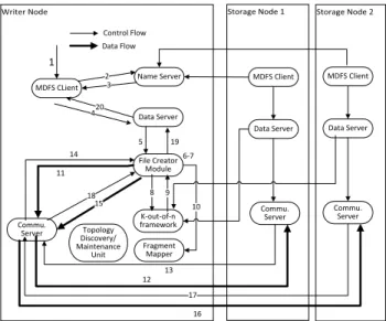
4.4.2 File Write Operation
HDFS write design is not applicable for MDFS as data cannot be written unless the block is decrypted and decoded. Hence in the MDFS architecture, when write operation is called, bytes are appended to the current block till the block boundary is reached or the file is closed. The block is then encrypted, split into fragments and redistributed across the cluster.
Our MDFS architecture does not support random writes. Random writes make the design more compli-cated when writes span across multiple blocks. This feature is not considered in the present design as it is not required for the MapReduce framework. Figure 6 illustrates the control flow of a write operation through these numbered steps
Step 1: The user issues a write request for a file of
lengthL. The file is split into blocks of size [L/B] where
Bis the user configured block size. The last block might
not be complete depending on the file length. The user request can also be a streaming write where the user writes to the file system byte by byte. Once the block boundary is reached or when the file is closed, the block is written to the network. In both scenarios, the data to be written is assumed to be present in the local file system.
Step 2: Similar to HDFS block allocation scheme,
for each block to be written, the MDFS client requests the Name Server to allocate a new block Id which is a unique identifier for each block. As all the identifiers are generated by a single Name Server in a centralized architecture, there will not be any identifier. However, in the distributed architecture, an appropriate hashing function is required to generate the unique global iden-tifier. In our implementation, the absolute path of each file is used as the hash key.
Step 3: The Name Server returns a new block id
based on the allocation algorithm and adds the block identifier in its local cache. The mapping of file to list of blocks is stored in the Name Server.
Steps 4-5:The MDFS client issues a creation request
to the Data Server which contains a specific opcode in the request message. The Data Server identifies the opcode and instantiates the File Creator module to handle the block creation.
Step 6: The block stored in the local file system is
encrypted using the secret key. The encrypted block is
partitioned intonfragments using erasure encoding.
Step 7: The key is also split into fragments using
Shamir’s secret key sharing algorithm.
Steps 8-9:The Data Server requests thek-out-of-n
framework to providen storage nodes such that total
expected transmission cost from any node tok closest
storage nodes is minimal.
Step 10: The Data Server requests the Fragment
Mapper to add the fragment information of each file which includes the fragment identifier with the new
locations returned by thek-out-of-nframework. If the
network topology changes after the initial computation,
k-out-of-n framework recomputes the storage nodes
for every file stored in the network and updates the Fragment Mapper. This ensures that Fragment Mapper is always in sync with the current network topology.
Steps 11-18: The file fragments are distributed
in parallel across the cluster. The key fragments are also stored in the same manner. These details are not included in the diagram for brevity.
Steps 19-20: Once the file and key fragments are
distributed across the cluster, the Data Server informs the client that the file has been successfully written to the nodes. For security purposes, the original block stored in the local file system of the writer is deleted after the write operation as it is no longer needed.
2168-7161 (c) 2016 IEEE. Personal use is permitted, but republication/redistribution requires IEEE permission. See http://www.ieee.org/publications_standards/publications/rights/index.html for more
4.4.3 File Append Operation
MDFS supports Append operation which was intro-duced in Hadoop 0.19. If a user needs to write to an existing file, the file has to be open in append mode. If the user appends data to the file, bytes are added to the last block of the file. Hence, for block append mode, the last block is read into the local file system of the writer and the file pointer is updated appropriately to the last written byte. Then, writes are executed in a similar way as described in the previous section.
4.4.4 File Delete Operation
For a file to be deleted, all file fragments of every block of the file have to be deleted. When the user issues a file delete request, the MDFS client queries the Name Server for all the blocks of the file. It then requests the Data Server to delete these blocks from the network. The Data Server gathers information about the file fragments from the Fragment Mapper and requests the Communication Server to send delete requests to all the locations returned by the Fragment Mapper. Once the delete request has been successfully executed, the corresponding entry in the Fragment Mapper is removed. In case of the distributed architecture, the update has to be broadcast to the network so that the entry is deleted from all nodes in the network.
4.4.5 File Rename Operation
The File Rename operation requires only an update in the namespace where the file is referenced with the new path name instead of the old path. When the user issues a file rename request, the MDFS client requests the Name Server to update its namespace. The Name Server updates the current inode structure of the file based on the renamed path.
4.4.6 Directory Create/Delete/Rename Operations
When the user issues the file commands to create, delete or rename any directory, the MDFS client requests the Name Server to update the namespace. The namespace keeps a mapping of each file to its parent directory where the topmost level is the root directory (’/’). All paths from the root node to the leaf nodes are unique. Recursive operations are also allowed for delete and rename operations.
4.5 Energy-aware task scheduling
Hadoop Mapreduce framework relies on data locality
for boosting overall system throughput. Computation is moved closer to the nodes where the data resides. JobTracker first tries to assign tasks to TaskTrackers in which the data is locally present (local). If this is not possible (no free map slots or if tasks have already failed in the specific node), it then tries to assign tasks to other TaskTrackers in the same rack (non-local). This reduces the cross-switch network traffic thereby reducing the overall execution time of Map tasks. In case of non-local task processing, data has to be fetched
Algorithm 1: Task Scheduling
Input: Sb, Fb, d, k Output: X, C⋆ i // indexb inC ⋆ i(b)is omitted C⋆ i = 0 X ←−1×N array initialized to 0 D←− 1×N array for j=1 to N do D[j].node=j D[j].cost=(Sb/k)×Fb(j)×dij if D[j].cost== 0then D[j].cost=N2 //
Just assign a big number
end end
D←− SortD in increasing order by D.cost
for i=1 to k do X[D[i].node]=1 C⋆ i += D[i].cost end return X, C⋆ i
from the corresponding nodes, adding latency. In a mobile environment, higher network traffic leads to increased energy consumption which is a major concern. Therefore, fetching data for non-local data processing results in higher energy consumption and increased transmission cost. Hence, it is important to bring Map Task processing nearer to the nodes that store the data for minimum latency and maximum energy efficiency.
There are many challenges in bringing data locality to MDFS. Unlike native Hadoop, no single node running MDFS has a complete data block; each node has at most one fragment of a block due to security reasons. Consequently, the default MapReduce scheduling al-gorithm that allocates processing tasks closer to data
blocks does not apply. When MDFS performs a read
operation to retrieve a file, it finds the k fragments that can be retrieved with the lowest data transferring
energy. Specifically, the k fragments that are closest
to the file requester in terms of the hop-count are retrieved. As a result, knowing the network topology (from the topology maintenance component in MDFS) and the locations of each fragment (from the fragments mapper), we could estimate the total hop-count for each
node to retrieve the closest k fragments of the block.
Smaller total hop-count indicates lower transmission time, lower transmission energy, and shorter job com-pletion time. Although this estimation adds a slight overhead, and is repeated again when MDFS actually retrieves/reads the data block, we leave the engineering optimization as the future work.
We now describe how to find the minimal cost (hop-count) for fetching a block from a taskTracker. Al-gorithm 1 illustrates the main change made to the default Hadoop MapReduce scheduler such that the data transferring energy is taken into account when scheduling a task. The improved scheduler uses the current network condition (topology and nodes’ failure
2168-7161 (c) 2016 IEEE. Personal use is permitted, but republication/redistribution requires IEEE permission. See http://www.ieee.org/publications_standards/publications/rights/index.html for more
probability) to estimate the task retrieval energy and assign tasks. Only nodes that are currently functional
and available may be selected. C⋆
i(b) is defined as the
minimal cost of fetching blockb at node i. LetFb be a
1×N binary vector where each elementFb(j) indicates
whether nodejcontains a fragment of blockb(note that
PN
j=1Fb(j) =n ∀b); Sb is the size of block b; di,j is
the distance (hop-count) between node i and node j;
the pair-wise node distance can be estimated efficiently
using all pair shorted distance algorithmX is a 1×N
binary decision variable where Xj = 1 indicates that
nodej sends a data fragment to nodei.
C⋆ i(b) = min N X j=1 (Sb/k)Fb(j)di,jXj, s.t. N X j=1 Xj =k C⋆
i(b) can be solved by Algorithm 1, which minimizes
the communication cost for node i to retrieve k data
fragments of blockb. OnceC⋆
i(b) for each node is solved,
the processing task for blockbis then assigned to node
p where p = arg miniCi⋆(b). The time complexity of
Algorithm 1 isN logN due to the sorting procedure, and
because it is performed once for each of theN node, the
time complexity for assigning a block to a taskTracker
isN2logN. Considering the size of our network (≤100)
and the processing power of the modern mobile devices, the computational overhead of the scheduling algorithm is minimal.
4.6 Consistency Model
Like HDFS, MDFS also follows single writer and multi-ple reader model. An application can add data to MDFS by creating a new file and writing data to it (Create Mode). The data once written cannot be modified or removed except when the file is reopened for append (Append Mode). In both write modes, data is always added to the end of the file. MDFS provides the support for overwriting the entire file but not from any arbitrary offset in the file.
If an MDFS client opens a file in Create or Append mode, the Name Server acquires a write lock on the corresponding file path so that no other client can open the same file for write. The writer client periodically notifies the Name Server through heartbeat messages to renew the lock. To prevent the starvation of other writer clients, the Name Server releases the lock after a user configured time limit if the client fails to renew the lock. The lock is also released when the file is closed by the client.
A file can have concurrent reader clients even if it is locked for a write. When a file is opened for a read, the Name Server acquires a read lock on the corresponding file path to protect it from deletion from other clients. As the writes are always executed in the local file system, the data is not written to the network unless the file is closed or the block boundary is reached. So, the changes made to the last block of the file may not be visible to the reader clients while the write operation
is being executed. Once the write has completed, the new data is visible across the cluster immediately. In all circumstances, MDFS provides strong consistency guarantee for reads such that all concurrent reader clients will read the same data irrespective of their locations.
4.7 Failure Tolerance
This section describes how MDFS uses k-out-of-n
en-coding technique and snapshot operation to improve the data reliability and prevent node failures.
4.7.1 k-out-of-n reliability
In HDFS, each block is replicated a specific number of times for fault tolerance, which is determined by the replication factor configured by the user. In MDFS, the
k-out-of-n framework ensures data reliability where k
andnparameters determine the level of fault tolerance.
These parameters are per file configurable which are
specified at the file creation time. Only k nodes are
required to retrieve the complete file, ensuring data reliability.
4.7.2 Snapshot operation
A snapshot operation creates a backup image of current state which includes in-memory data structures. During safe shutdown of the Name Server and Fragment Map-per, a snapshot operation is automatically invoked to save the state on the disk. On restart, the saved image is used to rebuild the system state. Snapshot operations are particularly useful when a user is experimenting with changes that need to be rolled back easily in the future. When client requests a snapshot operation, the Name Server enters a special maintenance state called safe mode. No client operations are allowed when the Name Server is in safe mode. The Name Server leaves safe mode automatically once backup is created. The data server is not backup as it mainly handles MDFS communication tasks like neighbor discovery, file creation, file retrieval. These information varies with time, so it is unnecessary to include in the snapshot.
4.8 Diagnostic Tools
MDFS Shell is a handy and powerful debugging tool to execute all available file system commands. It is invoked
by hadoop mdfs<command><command args>. Each
command has file path URI and other command specific arguments. MDFS shell can simulate complex cluster operations like concurrent reads and writes, device fail-ures, device reboots etc. All MDFS specific parameters can be changed at run time using MDFS shell. MDFS shell is particularly useful in testing new features and analyzing its impact on overall performance of the system. All file system operations are logged in a user specific folder for debugging purposes and performance analysis. If any issue is encountered, the operation logs can be used to reproduce the issue and diagnose it.
2168-7161 (c) 2016 IEEE. Personal use is permitted, but republication/redistribution requires IEEE permission. See http://www.ieee.org/publications_standards/publications/rights/index.html for more
5
System Implementation
We have used Apache Hadoop stable release 1.2.1 [21] for our implementation. Our MDFS framework consists of 18,365 lines of Java code, exported as a single jar file. The MDFS code does not have any dependency on the Hadoop code base. Similar to DistributedFileSystem class of HDFS, MDFS provides MobileDistributedFS class that implements FileSystem, the abstract base class of Hadoop for backwards compatibility of all present HDFS applications. The user invokes this object to interact with the file system. In order to switch from HDFS to MDFS, the Hadoop user only needs to add the location of jar file to the HADOOP CLASSPATH variable and change the file system scheme to ‘mdfs’. The parameter ‘mdfs.standAloneConf’determines the MDFS architecture to be instantiated. If it is set to false, all the servers are started locally as in the distributed architecture. If it is set to true, the user needs to additionally configure the parameter ‘mdfs.nameservice.rpc-address’to specify the location of Name Server. In the present implementation, the Frag-ment Mapper is started in the same node as the Name Server. Since no changes are required in the existing code base for MDFS integration, the user can upgrade to a different Hadoop release without any conflict.
6
Performance Evaluation
In this section, we present performance results and identify bottlenecks involved in processing large input datasets. To measure the performance of MDFS on mobile devices, we ran Hadoop benchmarks on a hetero-geneous 10 node mobile wireless cluster consisting of 1 personal desktop computer (Intel Core 2 Duo 3 GHz processor, 4 GB memory), 10 netbooks (Intel Atom 1.60 GHz processor, 1 GB memory, Wi-Fi 802.11 b/g interface) and 3 HTC Evo 4G smartphones running Android 2.3 OS (Scorpion 1Ghz processor, 512 MB RAM, Wi-Fi 802.11 b/g interface). As TaskTracker daemons are not ported to the Android environment yet, smartphones are used only for data storage, and not for data processing. Note that although the Hadoop framework is not yet completely ported to Android smartphones in our experiment, which will be our future work, the results obtained from the netbooks should be very similar to the results on real smartphones as modern smartphones are equipped with more powerful CPU, larger memory, and higher communication band-width than the netbooks we used.
We used TeraSort, a well-known benchmarking tool that is included in the Apache Hadoop distribution. Our benchmark run consists of generating a random input data set using TeraGen and then sorting the generated data using TeraSort. We considered the following metrics: 1) Job completion time of TeraSort; 2) MDFS Read/Writes Throughput; and 3) Network bandwidth overhead. We are interested in the following parameters: 1) Size of input dataset; 2) Block Size; and
300 310 320 330 340 350 360 370 380 390 400 0 2 4 6 8 10
Hadoop Job Time (sec)
Block Size (MB) TeraSort of 50 MB DataSet (a) 300 320 340 360 380 400 4 5 6 7 8 9 10
Hadoop Job Time (sec)
Cluster Size TeraSort of 50 MB DataSet
(b)
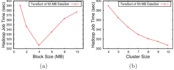
Fig. 7. Effect of (a) Block size (b) Cluster size on Job Completion Time
3) Cluster Size. Each experiment was repeated 15 times
and average values were computed. The parametersk
and n are set to 3 and 10, respectively for all runs.
Each node is configured to run 1 Map task and 1 Reduce task per job, controlled by the parameters ‘mapred.tasktracker.map.tasks.maximum’and
‘mapred.tasktracker.reduce.tasks.maximum’respectively. As this paper is the first work that addresses the challenges in processing of large datasets in mobile environment, we do not have any solutions to compare against. MDFS suffers the overhead of data encoding/decoding and data encryption/decryption, but MDFS achieves better reliability and energy-efficiency. Furthermore, MDFS uses Android phones as storage nodes and performs read/write operations on these phones, but HDFS data node is not ported on Android devices. As a result, it is difficult to compare the performance between HDFS and MDFS directly.
6.1 Effect of Block Size on Job Completion Time
The parameter ‘dfs.block.size’ in the configuration file determines the default value of block size. It can be overridden by the client during file creation if needed. Figure 7(a) shows the effect of block size on job com-pletion time. For our test cluster setup, we found that the optimal value of block size for a 50MB dataset is 4 MB. The results show that the performance degrades when the block size is reduced or increased further.
A larger block size will reduce the number of blocks and thereby limit the amount of possible parallelism in the cluster. By default, each Map task processes one block of data at a time. There has to be sufficient number of tasks in the system such that they can be run in parallel for maximum throughput. If the block size is small, there will be more Map tasks processing lesser amount of data. This would lead to more read and write requests across the network proving to be costly in a mobile environment. Figure 7(a) shows that processing time is 70% smaller than the network transmission time for TeraSort benchmark. So, tasks have to be sufficiently long enough to compensate the overhead in task setup and data transfer for maximum throughput. For real world clusters, the optimal value of block size will be experimentally obtained.
2168-7161 (c) 2016 IEEE. Personal use is permitted, but republication/redistribution requires IEEE permission. See http://www.ieee.org/publications_standards/publications/rights/index.html for more 0 0.2 0.4 0.6 0.8 1 0 1 2 3 4 5 6 7 8
Job Completion rate
Number of node failures HDFS (1,3) MDFS (3,9) (a) 260 280 300 320 340 360 380 400 1 2 3 4 5 6 7 8 9
Hadoop Job Time (sec)
Number of Iterations
1 node failed 2 node failed
3 node failed
Terasort of 100 MB DataSet (sec)
(b)
Fig. 8. Effect of (a) Comparison of job completion rate between HDFS and MDFS (b) Job time vs. Number of failures.
6.2 Effect of Cluster Size on Job Completion Time
The cluster size determines the level of possible paral-lelization in the cluster. As the cluster size increases, more tasks can be run in parallel, thus reducing the job completion time. Figure 8(b) shows the effect of cluster size on job completion time. For larger files, there are several map tasks that can be operated in parallel depending on the configured block size. So the performance is improved significantly with increase in cluster size as in the figure. For smaller files, the performance is not affected much by the cluster size, as the performance gain obtained as part of parallelism is comparable to the additional cost incurred in the task setup.
6.3 Effect of node failures on MDFS and HDFS
In this section, we compare the fault-tolerance capabil-ity between MDFS and HDFS. We consider a simple failure model in which a task fails with its processor node and a taskTracker can not be restarted once it fails (crash failure). There are total 12 nodes in the network. In HDFS, each data block is replicated to 3 different nodes, and HDFS can tolerate to lose at most 2 data nodes; in MDFS, each data block is encoded and
stored to 9 different nodes (k= 3, n= 9), and MDFS
can tolerate to lose up to 6 data nodes. The reason we
set parameter (k, n) = (3,9) in this experiment (rather
using the same n= 10 in the previous experiments) is
that (k, n) = (3,9) has the same data redundancy as the
default HDFS 3-Replication scheme. This experiment is independent to the previous experiments in which
n= 10. Note that although HDFS can tolerate to lose
at most 2 data nodes, it does not mean that the job would fail if more than 2 nodes fail; if the failed node does not carry the data block of the current job, it does not affect the taskTracker; as a result, we see completion rate gradually drops from 1 after more than 3 nodes fail. Figure 8(a) shows that MDFS clearly achieves better fault-tolerance when 3 or more nodes fail.
6.4 Effects of Node Failure Rate on Job Completion
Time
Our system is designed to tolerate failures. Figure 7(b) shows the reliability of our system in case of node failures. The benchmark is run for 10 iterations for
1 1.5 2 2.5 3 4 8 12 16 20 24 MDFS Throughput (MB/s)
Size of Input Dataset (MB) MDFS Write MDFS Read (a) 0 0.5 1 1.5 2 2.5 3 1 2 3 4 5 6 7 MDFS Throughput (MB/s)
Size of Input Dataset (MB) MDFS Write MDFS Read
(b)
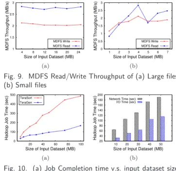
Fig. 9. MDFS Read/Write Throughput of (a) Large files (b) Small files 0 100 200 300 400 500 20 40 60 80 100
Hadoop Job Time (sec)
Size of Input Dataset (MB) TeraSort TeraGen (a) 20 40 60 80 100 120 140 160 180 200 10 20 30 40 50
Hadoop Job Time (sec)
Size of Input Dataset (MB) Network Time (sec)
I/O Time (sec)
(b)
Fig. 10. (a) Job Completion time v.s. input dataset size (b) Processing time vs. Transmission time
100 MB data. Node failures are induced by turning off the wireless interface during the processing stage. This emulates real world situations wherein devices get disconnected from the network due to hardware or connection failures. In Figure 7(b), one, two and three simultaneous node failures are induced in iterations 3, 5 and 8 respectively and original state is restored in the succeeding iteration. The job completion time is increased by 10% for each failure but the system successfully recovered from these failures.
In the MDFS layer, the k-out-of-n framework
pro-vides data reliability. If a node containing fragments is
not available, thek-out-of-nframework chooses another
node for the data retrieval. Since k and n are set to
3 and 10 respectively, the system can tolerate up to 7 node failures before the data becomes unavailable. If any task fails due to unexpected conditions, Task-Trackers notify the JobTracker about the task status. JobTracker is responsible for re-executing the failed tasks on some other machine. JobTracker also considers a task to be failed if the assigned TaskTracker does not report the failure in configured timeout interval.
6.5 Effect of Input Data Size
Figure 9(a) and Figure 9(b) show the effect of input dataset size on MDFS throughput. The experiment measures the average read and write throughput for dif-ferent file sizes. The block size is set to 4 MB. The result shows that the system is less efficient with small files due to the overhead in setup of creation and retrieval tasks. Maximum throughput is observed for file sizes that are multiples of block size. This will reduce the to-tal number of subtasks needed to read/write the whole file, decreasing the overall overhead. In Figure 9(b), the throughput gradually increases when the input dataset size is increased from 1 MB to 4 MB because more data
2168-7161 (c) 2016 IEEE. Personal use is permitted, but republication/redistribution requires IEEE permission. See http://www.ieee.org/publications_standards/publications/rights/index.html for more
can be transferred in a single block read/write request. However, when input dataset size is increased further, one additional request is required for extra data and thus throughput drops suddenly. The results show that maximum MDFS throughput is around 2.83 MB/s for reads and 2.12 MB/s for writes for file sizes that are multiples of block size.
Figure 10 shows the effect of input dataset size on job completion time. The experiment measures the job completion time for different file sizes ranging from 5 MB to 100MB. Files generated in mobile devices are unlikely to exceed 100 MB. However, MDFS does not have any hard limit on input dataset size and it can take any input size allowed in the standard Hadoop release. The result shows that the job completion time varies in less than linear time with input dataset size. For larger datasets, there is a sufficient number of tasks that can be executed in parallel across the cluster resulting in better node utilization and improved performance.
6.6 Centralized versus Distributed Architecture
The major difference between the distributed solution and the centralized solution is that nodes in distributed solution need to continuously synchronize their Name Server and Fragment Mapper. Due to the synchro-nization, the distributed solution needs to broadcast directory information after a file is created or updated. The broadcast messages directly impact the perfor-mance difference between the centralized architecture and the distributed architecture. When a MapReduce job has more read operations, distributed architecture might perform better as all metadata information can be queried locally rather than contacting the centralized server; when a MapReduce task has more write opera-tions, centralized architecture might perform better due to lesser broadcast messages.
Figure 11(a) compares the number of broadcast mes-sages sent during file creation for different input dataset sizes. The block size is set to 4 MB. As input dataset size increases, the number of file blocks also increases. In a distributed architecture, each block allocation in Name Server and subsequent fragment information update in Fragment Mapper needs to be broadcast to all other nodes in the cluster so that their individual caches re-main in sync with each other. Large usage of bandwidth makes broadcasting a costly operation in wireless net-works. This effect is much worse when the cluster size grows. Figure 11(b) compares the number of broadcast messages sent during file creation for varying cluster sizes. The updates are not broadcast in a centralized approach as the Name Server and Fragment Mappers are singleton instances.
The results prove that the distributed architecture is ideal for medium sized clusters with independent devices and no central server. The overhead due to broadcasting is minimal if the cluster is not large. For large clusters, the communication cost required to keep the metadata synchronized across all nodes becomes
0 50 100 150 200 250 300 350 400 0 10 20 30 40 50 # of Broadcast Packets
Size of Input Dataset (MB)
Distributed Architecture Centralized Architecture (a) 0 50 100 150 200 250 300 350 400 4 5 6 7 8 9 10 # of Broadcast Packets Cluster Size Distributed Architecture Centralized Architecture (b)
Fig. 11. Effect of (a) Input dataset size on Network bandwidth overhead in Centralized and Distributed Archi-tecture (b) Cluster size
0 200 400 600 800 1000 1200 1400 1600 0 20 40 60 80 100
Hadoop Job Time (sec)
Size of Input Dataset (MB)
TeraGen-EnergyUnaware TeraGen-EnergyAware TeraSort-EnergyUnaware TeraSort-EnergyAware
Fig. 12. New task scheduling algorithm vs. Random
significant. Hence, a centralized approach is preferred in large clusters. However, data reliability is guaranteed
byk-out-of-nframework in both architectures.
6.7 Energy-aware task scheduling v.s. Random task
scheduling
As mentioned in Section 4.5, our energy-aware task scheduling assigns tasks to taskTrackers considering the locations of data fragments. The default task scheduling algorithm in Map-Reduce component is ineffective in mobile ad-hoc network as the network topology in a traditional data center is completely different from a mobile network. Figure 12 compares the job completion time between our energy-ware scheduling algorithm and a random task scheduling. The default Map-Reduce task scheduling in a mobile ad-hoc network is
essen-tially a random task allocation. In bothTeraGen and
TeraSort experiments, our scheduling algorithm effec-tively reduces the job completion time by more than 100%. Lower job completion time indicates lower data retrieval time and lower data retrieval energy of each taskTracker.
7
Roadmap for Mobile Hadoop 2.0
Porting both the jobTracker and the taskTracker dae-mons to the Android environment is our ongoing work. In future, we plan to integrate the energy-efficient
and fault-tolerantk-out-of-nprocessing framework
pro-posed in [9] into the Mobile Hadoop to provide better energy-efficiency and fault-tolerance in a dynamic net-work. We will also look into the heterogeneous prop-erties of the hardware and prioritize between various