I
S
YSTEM
-
LEVEL
M
ODELING OF
P
ROGRAMMABLE
P
ACKET
P
ROCESSING
S
YSTEMS
UMAIR AFTAB
A Thesis In The Department OfElectrical and Computer Engineering
Presented in Partial Fulfillment of the Requirements for the
Degree of Master of Applied Science (Electrical and Computer Engineering) At
Concordia University Montréal, Québec, Canada
July 2016
II
CONCORDIA UNIVERSITY
School of Graduate Studies
This is to certify that the thesis prepared By: Umair Aftab
Entitled: “System-level Modeling of Programmable Packet Processing Systems” and submitted in partial fulfillment of the requirements for the degree of
Master of Applied Science (Electrical and Computer Engineering)
complies with the regulations of the University and meets the accepted standards with respect to originality and quality.
Signed by the final examining committee:
Chair
Examiner
Examiner
Supervisor
Approved by
Chair of Department or Graduate Program Director
Dean of Faculty
III
ABSTRACT
Computer networks are experiencing explosive growth which is reinforced by the recent exhaustion of the global IPv4 addresses space in 2011 and the tenfold increase in users from 1999 to 2013. The advent of cloud, mobile and IoT is only going to accelerate this growth. This accedes the need for flexible and scalable networks that process packets faster. Programmable packet processing systems have emerged as a solution which aim to find balance between flexibility of supporting different processing functions while maintaining a high processing capability. Designing architectures that support such paradigms is fairly complicated as decisions need to be made for evaluating trade-offs between flexibility and efficiency. Questions like what programmatic interfaces, services, applications and protocols are required need to be answered before synthesis of actual hardware. To evaluate such requirements modelling techniques are required to evaluate architecture decisions accurately early enough in the design phase.
In this thesis, we propose a flexible system level modelling methodology for early validation, design and analysis of packet processing applications for programmable forwarding plane architectures. The hardware and software architecture is described in a high level language which can be used to describe forwarding planes from many core network processors to reconfigurable processing pipelines. Device architects can use this for design space exploration, prototyping and validation; where application developers can start pre-silicon application design, development and debugging to evaluate different hardware and software decisions in an industry with ever shrinking market windows.
IV
ACKNOWLEDGEMENTS
I would like to thank my supervisor Dr. Samar Abdi for guiding me throughout my research work. My work under his guidance has not only improved my technical and presentation skills but has improved my grasp of system level design and modelling approaches as a whole. I highly appreciate the open minded view and clear-sighted objective guidance towards new ideas and opportunities, for which I am greatly thankful.
I would like to thank the work of my project team members Gordon Bailey, Shafigh Parsazad, Eric Trembley, Kamil Saigol and Faras Dewal without whom all this would not have been possible. I would also like to acknowledge Ericsson Research Canada and NSERC for funding this research project and providing with the required industry direction and technical expertise.
Finally I would like to thank my parents for all of their support. EX NIHILO NIHIL FIT
V
Contents
Chapter 1: Introduction ... 1 1.1. Packet Processing ... 3 1.2. Motivation ... 4 1.3. Thesis Contribution ... 61.3.1. Memory Abstraction Layer for Host-Compiled Models ... 6
1.3.2. Forwarding Architecture Description ... 6
1.3.3. Automatic Model Generation ... 7
1.4. Related Work... 8
Chapter 2: Programmable Forwarding Planes ... 9
2.1. Forwarding Plane Programming ... 10
2.1.1. P4 - Protocol Independent Programming Abstraction ... 11
2.2. Forwarding Architectures ... 12
2.2.1. Soft Switch ... 13
2.2.2. Network Processor ... 14
2.2.2.1. NPU Packet Flow ... 15
2.2.3. Reconfigurable Pipelines ... 16
2.3. Simulation Techniques ... 18
2.3.1. Instruction Set Simulation ... 20
2.3.1.1. Interpretive ISS ... 21
2.3.1.2. Statically Compiled ISS... 22
2.3.1.3. Dynamically Compiled ISS ... 23
2.3.2. Host Compiled Simulation ... 24
2.4. Summary ... 26
Chapter 3: Modelling Forwarding Architectures ... 27
3.1. Transaction-level Modeling in SystemC ... 28
3.1.1. TLM timing annotations ... 29
Untimed ... 29
Loosely timed ... 29
Approximately timed ... 30
VI
3.1.2.1. Blocking transport interface (b_transport) ... 32
3.1.2.2. Non-blocking transport interface (nb_transport) ... 32
3.2. Modelling Memory ... 33
3.3. Modelling the Memory Controller ... 35
3.4. Modelling Fixed Function Modules ... 37
3.5. Soft switch Model Semantics ... 39
3.6. NPU Model Semantics ... 39
3.7. RMT Model Semantics ... 40
3.8. Summary ... 42
Chapter 4: Hardware Abstraction Layer Modelling ... 43
4.1. Memory Access Redirection – TLMVAR ... 46
4.1.1. C++ objects and the Memory Model ... 46
4.1.1.1. Allocation and initialization ... 47
a. C++ Classes ... 47
b. Plain Old Data types ... 47
4.1.1.2. Access operators ... 48
4.1.2. Redirection for C++ classes ... 48
4.1.3. Redirection for POD Types ... 49
4.1.4. Assembling the SW stack ... 50
4.1.5. Limitations of TLMVAR... 53
4.2. Integration with packet processing programs (P4/C++) ... 54
4.3. Summary ... 55
Chapter 5: Automatic Model Generation ... 56
5.1. Forwarding Architecture Description... 56
5.1.1. Interface ... 57
5.1.2. Communication Element ... 58
5.1.3. Processing Element... 58
5.1.3.1. Top-Level PE ... 59
5.1.4. Bind - connections in FAD ... 60
5.1.5. Service ... 60
5.2. FAD Platform generator ... 61
VII
5.2.1.1. Lexical Analyzer ... 64
5.2.1.2. Parser ... 65
5.2.2. Intermediate Representation ... 65
5.2.3. Compiler Backend - SystemC Translation ... 66
5.2.3.1. Interface & Service ... 67
5.2.3.2. Processing Element... 68
5.2.3.3. Communication Elements... 70
5.2.3.4. Bindings ... 71
5.3. Summary ... 71
Chapter 6: Experimental Results ... 72
6.1. Architectural Exploration ... 72 6.1.1. Evaluation Criteria ... 72 6.1.2. Test Cases ... 73 6.1.3. Test Models ... 74 6.1.4. Results ... 75 6.1.5. Simulation Speed ... 76
6.1.6. Average Packet Latency Estimation ... 77
6.1.7. Accuracy ... 78 6.2. Algorithm Evaluation ... 79 6.2.1. Test Environment ... 80 6.2.2. Test Cases ... 81 6.2.3. Results ... 85 6.2.4. Trie Performance ... 85 6.2.5. Lookup performance... 86
Chapter 7: Conclusion and Future Work ... 88
Chapter 8: References ... 90
Chapter 9: Appendix – A ... 93
VIII
List of Figures
Figure 1 SDN Architecture ... 2
Figure 2 Modelling methodology ... 8
Figure 3 Virtualizing switches embedded in Hypervisors [41] ... 13
Figure 4 Typical Network Processor Architecture ... 15
Figure 5 Reconfigurable Match Table Pipeline Architecture ... 17
Figure 6 Comparison of modelling at various abstraction levels ... 19
Figure 7 Interpretive ISS simulation flow ... 21
Figure 8 Design flow from algorithms to silicon ... 24
Figure 9 Simulation Environment ... 27
Figure 10 TLM - Loosely timed annotation – temporal decoupling. ... 29
Figure 11 TLM Approximate timing annotation points ... 30
Figure 12 TLM Socket communication ... 31
Figure 13 High level modelling of a processor. ... 32
Figure 14 Memory CE interface ... 34
Figure 15 On-Chip network access to Memory ... 35
Figure 16 Memory PE ... 36
Figure 17 Design Pattern for fixed function modules ... 37
Figure 18 Behavioural design of fixed function modules ... 38
Figure 20 Application exclusively uses the host memory ... 43
Figure 21 TLMVAR operation flowchart ... 52
Figure 22 FAD Interface ... 57
IX
Figure 24 PFPSim Modelling Workflow ... 61
Figure 25 FAD Compiler Layout ... 62
Figure 26 FAD Compiler Frontend... 63
Figure 27 PE SystemC implementation ... 68
Figure 28 Functional Validation of Models ... 74
Figure 29 Wall clock time for Simulation runs ... 76
Figure 30 Average Packet latency of test designs ... 77
Figure 31 Prefix Tree representation ... 81
Figure 32 LC Trie representation ... 82
Figure 33 MultiBit Trie ... 84
Figure 34 Trie Memory Footprint ... 86
X
List of Tables
Table 1 Comparison of full system cycle accurate simulators ... 22
Table 2 TLMVAR operator overloads ... 49
Table 3 FAD Lex tokenization regular expressions ... 64
Table 4 Experimental Results ... 75
XI
Code Listings
Listing 1 Virtual functions declared by the memory interface ... 33
Listing 2 Memory CE implementation of the read function. ... 34
Listing 3 HAL implementation of the write function ... 45
Listing 4 TLMVAR support for POD types ... 50
Listing 5 TLMVAR write implementation ... 51
Listing 6 FAD Example ... 56
Listing 7 Minimal FAD specification ... 59
Listing 8 Minimal C++ Program ... 59
Listing 9 FAD Parser BNF example ... 65
Listing 10 FAD HLIR format ... 66
Listing 11 Interface SystemC implmentaton ... 67
Listing 12 FAD PE SystemC Implementation ... 69
Listing 13 FAD CE SystemC implementation ... 70
1
Chapter 1:
Introduction
Computer networks are growing at an unprecedented rate with the addition of smartphone and handheld devices. With the advent of the cloud most applications are being pushed online to datacenters. The distinction between what is mobile content and what is not is being increasing blurred. Content creators pushing towards a more unified experience towards all devices fixed or mobile. To keep up with this ISPs, Mobile network operators and datacenter designers need to design networks that are no longer static but instead can scale, react and be managed easily.
Networks deploy a slew of devices from switches and routers to firewalls, load balances and intrusion detection boxes. Historically to monitor and configure, network vendors have had to solely rely on CLI or SNMP agents. CLI due to its inherent nature requires configuration to be done individually for every device in the network. SNMP by design is iterative and inefficient, parallel connections need to be polled since devices do not have the ability to subscribe to configuration streams over TCP or report back failures. Although some proprietary network management tools offer a central point for configuration, these tools still function on individual protocols and configuration interfaces. This mode of operation does not offer introspection into the operational state of the network, only a limited set of metrics can be collected to gauge the health of a network which again are highly device and vendor dependent since the implementation of protocols is often proprietary and run in black boxes. This increases network complexity, capital requirements and operational overhead for the operator to run the network.
This has given rise to rapid adoption of paradigms like Software Defined Networking (SDN) in recent years, by both network operators and several switch chip vendors offering support for the OpenFlow protocol [1] to implement SDN architectures. SDN abstracts and ramifies
2
network systems which make decisions of where the traffic should go from the underlying systems that actually route network traffic, these are referred to as the control plane and forwarding plane respectively. The question we need to ask is what problem does SDN solve? The customary answer is automating configuration management. It does so by assimilating network control of multiple operation points into a single software control program. This approach enables programmable network control because it decouples control of the network from forwarding functions allowing non-blocking asynchronous operation of routing and forwarding functions.
Figure 1 SDN Architecture
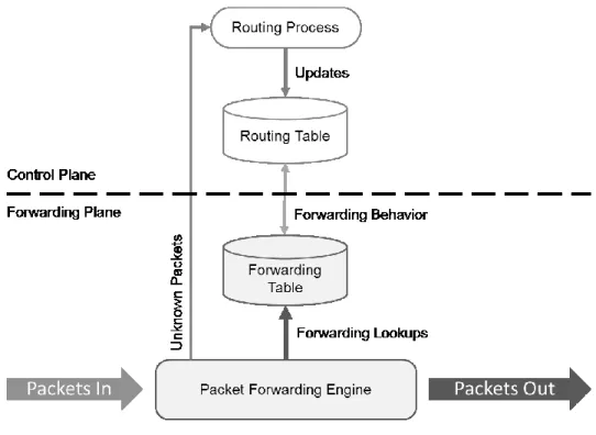
A Control Plane in a router makes the decision of where the traffic is sent. It configures, updates or modifies the routing tables for the data planes they manage according to the topology and metrics of the network by exchanging routing information with other routers over network discovery and routing protocols like BGP, RIP or OSPF.
3
Forwarding planes or data planes form part of the routing systems that actually handle network traffic. Packets are processed by using information from forwarding tables populated by the control plane to essentially figure out how to get the packet to its destination by forwarding it to the appropriate next hop in the network. The SDN prerogative is that the application executing on forwarding plane determines the type of device the forwarding plane represents.
A SDN switch (Control + Data plane) has one or more tables of rules for packet handling. Each rule matches a subset of the traffic which performs certain actions of a matching packet. Depending on the rules an SDN device can behave like a router, switch or a firewall or any combination of a network device. Designing architectures that support such paradigms is fairly complicated as decisions need to be made to evaluate trade-offs for programmable network elements that offer flexibility for new functional patterns while being scalable to support ever increasing network requirements. Questions like what programmatic interfaces, services, applications and protocols are required need to be answered before synthesis of actual hardware. To evaluate such requirements modelling techniques are required to evaluate architecture decisions accurately early enough in the design phase.
1.1.
Packet Processing
Packet processing applications by nature exhibit a high degree of data parallelism. In theory, stateless processing can be parallelized indefinitely, given enough processing and memory resources, since each processing thread works independently on a given packet. Moreover, most of the processing actions are fairly simple, often a sequence of arithmetic operations. The complexity, typically, lies in matching an incoming packet header against a set of header patterns stored in a table. The match type can be exact, longest-possible (longest-prefix), range or wildcard.
4
Forwarding device architects exploit the data parallelism in packet processing applications in one of two ways: either by using a large number of multi-threaded RISC cores or a deep pipeline. The former template is used in Network Processing Units (NPUs), while the latter is used in reconfigurable hardware pipelines. In order to mitigate the complexity of header field matching, architects use efficient search-and lookup data structures such as tries, or hardware accelerators such as ternary content-addressable memories (TCAMs) that perform single cycle matches.
To increase throughput and support higher bandwidth for networks forwarding planes need to be blazingly fast. Several design factors affect performance of forwarding planes for packets. The critical path in any forwarding plane can be defined as:
1. Ingress link layer deserialization and extracting the packet. 2. Identifying and decoding packet headers.
3. Processing packet – performing field lookups.
4. Sending packet through forwarding plane fabric (fixed-function processing elements). 5. Serialization and egress data link encapsulation.
1.2.
Motivation
Although SDN has seen rapid adoption among network operators and chip vendors by offering support for OpenFlow it is still however protocol dependent and is limited to known packet header types, this allows limited design space exploration for new efficient networking protocols and their performance. New proposals for protocol-independent programming abstractions like P4 have been proposed. These focus on describing how packets are processed regardless of the hardware implementation. This allows the support for different hardware while providing support for standard abstractions for programming forwarding planes.
5
The notion of a programmable forwarding plane is not new. Network processors (NPUs) and even general purpose CPUs have long been used in forwarding plane hardware [2], [3], [4]. Recently, we have seen the advent of new platforms, such as reconfigurable match table (RMT) [5] and FlexPipe [6] that utilize reconfigurable pipelined hardware for fast and programmable packet processing. Based on these trends, and the rapid pace at which networks are growing, network operators need to be able scale faster reacting to traffic demands, faults, and bad routing links. All the while optimizing on operation cost, performance and tolerance which determines the bottom line for the operator in a market whose time to market windows grow shorter and shorter with each financial quarter. This translates the need to develop faster flexible forwarding planes.
Shorter development cycles require co-development of software and hardware design cycles. Application developers want to develop, debug and analyze their packet processing programs even before the availability of silicon. System architects want to explore architectural options quickly. The design space for forwarding elements is multifaceted and diverse with each type of network application dictating its own set of workload and application requirements.
Having a model at the appropriate abstraction level provides a flexible path for design architects and application developers to narrow down the design space and explore optimal designs before deciding on an implementation. In order to support such an ecosystem, in this thesis we propose a simulation methodology to describe and generate host-compiled models of the hardware and low level software services. It reduces the modelling effort by describing the architecture in an abstract high-level language. The user can integrate packet processing applications like P4 by linking against this model. The simulation model can be traced to extract metrics like latency, drops, memory consumption, etc. This drives to establish and concretize the design requirements for the final implementation of the software stacks and the forwarding plane hardware.
6
1.3.
Thesis Contribution
The main contributions of this thesis are presented as follows:
1.3.1.
Memory Abstraction Layer for Host-Compiled Models
Host compiled simulations unlike instruction set simulators have the main limitation that all allocation and accesses of application happen directly on the host, although great for application development it does not give any indication of performance on the target platform, which can be observed in cycle-accurate simulators. Direct allocation allows host-compiled simulations to execute natively and not require the enormous modelling effort than their counterpart simulators. This however greatly limits the accuracy of the simulation for architectural evaluation and design trade-offs.In this thesis we present a novel compile time solution that leverages the C++ access and allocation semantics and the C++ memory model to provide a base layer which is used to redirect memory allocation and access to memory models instead of directly on the host.
1.3.2.
Forwarding Architecture Description
In the past the hardware design was primarily developed using VHDL and Verilog, as systems grow more and more complex, with increasing gate count for every generation and smaller process nodes, they present their own challenges in which the window to markets can no longer support years of chip development. Increasing faster development is vital to the design of modern electronic systems. The limitations and inexpressibility of Verilog and VHDL for software and algorithms gave rise to the development of concepts of TLM and SystemC in 2002. SystemC is C++ library with a discreet event simulation kernel. It provides all of the constructs of hardware
7
design languages like VHDL but allow the integration of normal C++ algorithms. This allows system level designers to model systems at higher abstraction levels for kick starting application development and evaluating architectural trade-offs in regards to system level design. Although SystemC provides an optimal integration of C++ and hardware modelling constructs it still befalls the trap of VHDL like languages that are too detailed of a specification language in which every detail of hardware has to be intricately described.
In this thesis we take the next step of building on top of the design approaches of SystemC and TLM to propose a faster approach of modelling systems which abstracts away a lot of the architectural specification details in a compact description to allow engineers to concentrate on the functionality of the system more than the implementation of the system in simulation.
1.3.3.
Automatic Model Generation
This thesis presents the forwarding architecture description language, but like every other language by itself it is useless if nothing can be done with it. We describe the implementation of the FAD to SystemC compiler, which generates a SystemC C++11 model from the description. The compiler generates all of the SystemC code base for the modules and their interconnections, this reduces the modelling effort for the designer and allows more focus on the behavioural aspect of the modules and developing applications for the platform. Since the FAD description is compiled, quick structural changes can be made to it which the compiler takes care of updating the SystemC code base for the model.
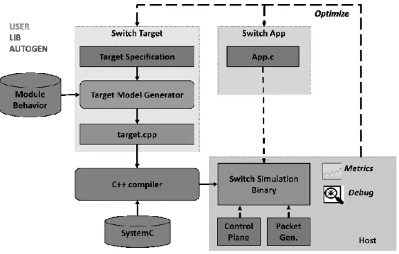
8
Figure 2 Modelling methodology
In addition to the compiler we provide a runtime library which has common utilities already available to the user for estimation, exploration and evaluation. The logic for the modules in the forwarding device is written in C++ by the user. The packet processing program to be executed by the programmable cores in the forwarding device is compiled and linked with the SystemC model of the forwarding device.
1.4.
Related Work
Comparatively there has been little work on system level modeling of programmable forwarding planes, given that the majority of switches in the market are fixed function. NePSim is a cycle-level network processor simulator which models the Intel IXP1200 architecture [7]. Since it models a specific Intel network processor, this makes it unsuitable to adapt for architectural exploration. There are SDN simulators and emulators, such as Mininet [8] and fs-SDN [9] but they do not model the forwarding plane architecture and are more geared towards emulating networks on the whole; such simulators are therefore unsuitable for evaluating design trade-offs.
9
There are processor simulators like MCSimA+ [10], Gem5 [11] and OVPSim [12] which perform full system simulation of x86 processing cores. Gem5 and OVPSim support for a variety of processor platforms like x86, ARM and PowerPC. PTLSim is another full system x86 cycle accurate Athlon micro architectural simulator. It models a modern superscalar out of order x86-64 processor core unlike OVPSim which is only instruction accurate.
These simulators can be used to model performance of soft-switch implementations but have difficulty scaling due to the detailed nature of instruction/cycle-level simulation, they cannot however model complete architectures of packet processing systems. To the best of our knowledge, there is currently no other published simulator than PFPSIM [3] that enables system-level modeling and simulation of programmable forwarding devices.
Chapter 2:
Programmable Forwarding Planes
The fundamental task of any forwarding element is to switch packets from its input to the appropriate output by modifying the appropriate headers of the packet according to its forwarding table. This can seem trivial but different applications have different requirements which dictate the trade-offs between complexity, speed and flexibility of implementations. Early switches were simple fixed function devices implemented as ASICs that switched packets at the L3/L2 level. Although ASIC implementations always afford us high-performance the trade-off is application flexibility and development cost.
As networks grow larger the design requirements change to accommodate more complex applications. The need for new efficient and flexible routing that scales stresses the development of new protocols and optimized algorithms in forwarding elements. Since most functionality in AISCS directly translates to silicon implementing new protocols and algorithms in most cases
10
requires respinning the whole chip which can take a long time to develop, synthesize and verify. Development cycles for ASICs fall in the range of years and cannot simply keep pace with rapid pace at which networks are evolving. This has given way to the development of distributed processing platforms like networks processors or deep pipelines like FlexPipe and RMT, each implementation gearing towards particular networking applications. This of course does not mean that ASICs are going to be fade out. As is with every industry they will get relegated to implementations where flexibility has to be sacrificed for applications with the most bleeding edge high performance requirements, e.g. Backbones and Regional Tier 1 networks.
2.1.
Forwarding Plane Programming
OpenFlow was introduced in 2007 as a way for software control planes to manage data planes switches. It is a standard that allows the population of forwarding tables such as Ethernet hash tables, Longest prefix match tables for IP and Wildcard searches for access control lists (ACL) to name a few by abstracting away hardware implementations. The OpenFlow conjecture is that switches are fixed-function in the sense that they have well known rigid functions that stem from and can be performed on protocols which are ratified by IEEE and IETF. In the first version of OpenFlow tables only for Ethernet, IPv4, VLANs, and ACLs [13] could be populated; later versions added support for more protocol headers like IPv6.
These protocols are usually directly implemented in silicon by ASIC networking chip vendors. Although OpenFlow focuses more on the standardization of the control plane software stack, the software stack of forwarding planes is usually bare metal provided by chip vendors which just expose the hardware-accelerated functions and don’t allow for much application flexibility for introducing more efficient transport or routing protocols.
11
OpenFlow has been more focused on assimilating control planes and management than operation of data planes, with data planes having OpenFlow agents which implement the specification and remains to be vendor controlled. This is why OpenFlow historically has been restricted to known packet header types and repeated extensions to the specification have been made to support new protocols. This makes it cumbersome to implement or even support new headers and protocols as they must be both agreed upon by OpenFlow and the chip vendors. Therefore, researchers have proposed new programming abstractions, such as P4 and Intel DPDK, for the forwarding plane in order to enable programming the forwarding chip to support new protocols [14].
The Intel DPDK framework is a set of libraries to accelerate packet processing in soft switches by abstracting away hardware and software environments by providing an application programming interface to available hardware accelerators, OS networking stack and other hardware like PCI bus controllers and DMA engines. It also provides a software stack for lockless queues, pre-allocated pools, circular buffers and low overhead asynchronous polling drivers. Although initially for x86 and Itanium processors it has been ported to other architectures like IBM POWER8.
2.1.1.
P4 - Protocol Independent Programming Abstraction
P4 aims to be a protocol independent programming abstraction by providing a standard API for developing applications which are compiled by a P4 Compiler targeted for a particular data plane architecture. It models an abstract forwarding element which generalizes how packets are processed in different forwarding devices. This abstract forwarding model is targeted to the hardware on top which a common language (P4) is used to express how packets are processed.
12
At minimum P4 assumes the following switch abstraction. Packets are switched via a programmable parser which parses headers of the packets. This is followed by multiple “match – action” stages which are used to match and apply entries from action tables which are representation of the forwarding information base in the forwarding element. These stages can be in parallel, or series or any combination of those, the order is implementation specific. After processing from these stages the packets are reconstituted into to the output data link format by the deparser from which they exit the data plane.
The programmable parser is the core of the protocol independent nature of P4 itself. The headers are specified by the user P4 application and the match action stage abstraction determines how packets are modified by determining which tables the packet matches against to apply the required action, where the action is the resulting modification of a header field.
The idea behind these efforts is to provide flexibility to the application developer in defining how packets are processed regardless of the underlying hardware [15]. The forwarding plane hardware providers, on the other hand, may distinguish their devices on cost, performance and power metrics, while providing support for standard programming abstractions.
2.2.
Forwarding Architectures
This section gives an overview of different types of forwarding architectures. Regardless of architecture design, a forwarding element as shown in figure 1 accepts a stream of packets. After basic header extraction and validation it looks up the route in the forwarding table. The lookup results in modifications to the packet headers and appropriate checksum updates. The resulting modified packet is output to the appropriate interface of the device. Forwarding elements may perform other packet processing functions depending upon the deployed application like traffic
13
shaping, QoS or payload inspection, this has given rise to different implementations like Soft switches, Network Processing Units and Pipelines.
2.2.1.
Soft Switch
Soft Switches are widely implemented inside datacenter servers completely running in software within virtual machine hypervisors like XenServer [16], Vmware [17] or Hyper-V [18]. They are typically deployed for networking virtual machines by providing a virtual network interface which is mapped to the physical network interface of the host machine. This allows virtual machines to access the network
in the same way as a physical machine would. Soft switches can also be used to form purely virtual networks if all of the virtual machines are completely within the datacenter subnet and don’t require outside access.
The fact that soft switches are
virtualized themselves allows them to be distributed also across various physical machines which simplifies network management as there is no need to create identical switches for each physical machine in this scenario; however it also increases the computational overhead on the host machine and can only scale to certain size to have realizable network latency.
Open vSwitch (OVS) [19] is a popular open source virtual switch. Proprietary solutions include VMware vSwitch [17] as part of the Esx/Esxi hypervisor networking fabric and Hyper-V Virtual Switch from Microsoft.
Figure 3 Virtualizing switches embedded in Hypervisors [41]
14
2.2.2.
Network Processor
Compared to soft switches network processing units are dedicated hardware geared towards particular networking applications. NPUs tend to strike a balance between the rigidity of full blown AISCs and the flexibility of soft switches. They are widely used in edge routers for performing high-touch functions like:
1. Pattern Matching: Accelerated regex functions to look for certain streams used in DPI.
2. Forwarding and Routing Lookups: Perform routing lookups and modify fields in packets using algorithms optimized for IP addresses and lookup data structures like tires or hash tables. To speed up certain types of lookups some NPUs use TCAM for variable length prefix lookups for L2-L4 processing or simple CAM for fixed-length MAC address lookups in L2 applications.
3. Queue Management: Quick allocation and re-circulation of packet buffers to implement QOS, ACL, Traffic policing & shaping.
4. Encryption and Decryption: Accelerated hardware provides cryptographic services for IPSEC by authenticating and encrypting packets of a session.
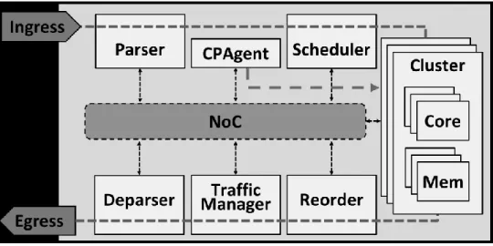
5. L2/L3 Header Processing: Header updates like port numbers and subsequent header processing that entails for checksum calculation and CRC updates to implement NAT. NPUs are also used as line cards and are used to offload networking operations that are best done in software. Due to the inherent parallel nature of the workload, NPU architects use a large number of multi-threaded RISC cores to exploit data parallelism, while providing the flexibility of software programming. Figure 4 illustrates the high-level architecture of a simplified
15
NPU, inspired by the SNP 4000 architecture [16]. To form the rest of the packet processing pipeline NPUs consists of configurable hardware units/co-processors for parsing, scheduling, reordering, traffic management and deparsing of packets. It comprises of multiple identical processing clusters, each made up of a set of general purpose processing cores, memories and hardware accelerators.
Figure 4 Typical Network Processor Architecture
2.2.2.1.
NPU Packet Flow
The control plane populates the match table entries in the NPU’s memory via an agent. This agent is typically part of the background processing cluster which by itself is not a part of the NPU’s packet processing pipeline, but performs background tasks like communicating with the control plane for FIB population, handling match table misses, reporting network state and etc. NPU’s receive packets at the ingress interface which are sent to the parser for header classification and generation of a packet descriptor. The scheduler then assigns the packet to one of the processing clusters. The packet processing application runs as concurrent identical threads on the CPU cores in the clusters, in a run-to-complete fashion. The application thread transforms the packet header, inspects the associated payload if needed, and then waits for the scheduler to send
16
the next packet. All of the cores in the clusters share the same bank of physical memory local to the cluster.
Since the bulk of the processing takes place on the processing clusters and the requirement to communicate with the same set of modules from all of these clusters NPU’s naturally lend themselves towards employing on-chip networks for communication between different elements to keep everything scalable.
The majority of the packet latency results from the search-and-lookup operations in memory from the processing taking place in the parallel cores in the cluster. Therefore, NPU designers can benefit from executable models that enable them to evaluate the trade-off between the number of cores and the budgeting of on-chip memory in their design. Such an executable model can also help with fast and early functional validation of the NPU architecture before hardware availability.
2.2.3.
Reconfigurable Pipelines
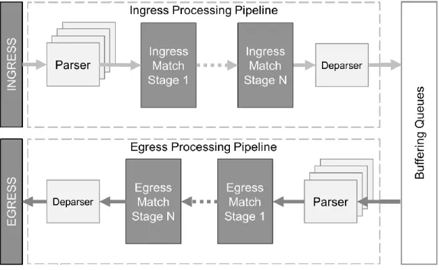
Pipeline architectures are currently theoretical and no current design exists in silicon one such is proposed in [5] It deploys the packet processing as a literal pipeline unlike the distributed architectures of NPUs. It employs parsers like the NPU which generates a packet header from packets arriving at ingress. The packet header travels through the pipeline in order on a wide header bus, with each stage executing a match action table. The match part of the stage uses TCAM or hash tables in SRAM for selecting the appropriate action in single cycle. The possible actions for a match-action table are preprogrammed as very wide instructions and stored in an SRAM section, dedicated to the relevant pipeline stage. A VLIW action processor executes the selected
17
instructions, and passes the packet header to the next stage. TCAM is used for wildcard matches and hash tables for exact matches.
Figure 5 Reconfigurable Match Table Pipeline Architecture
This obviously puts the constraint that the application running on the VLIW action processing units should ultimately be able to be expressed as a set of these match action stage memory lookups, which means unlike NPUs RMT cannot be used to perform higher-level functions like encryption/decryption locally. In RMT, the packet latency is constant and depends on the number of stages.
18
2.3.
Simulation Techniques
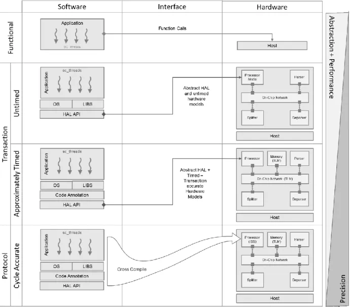
Simulation using virtual platforms has become a keystone for system-level design and validation by system architects. Architecture is replicated in software not only for just functional validation but also for early exploration into architecture design options and trade-offs, and most importantly to enable pre-silicon software development as time to market windows grow smaller with each development cycle. The techniques of software simulation used to be specific to application domains. Slow cycle accurate level modelling has been the purview of high performance computing domains focusing on complex architecture exploration, whereas the more resource constrained system on chip embedded domain privileged the co-design of hardware and software via fast and loosely timed transaction-level modelling. It is the recent convergence of these domains that demands for the confluence of design practices.
Function level modelling is just used for validation purposes to validate hardware against the initial algorithm proposal by comparing output traces under test for the set of same inputs. This however gives us no knowledge of the design of the system. Once algorithms are broken down to their structural components, we can model the interactions between these components as simple transactions as shown in figure 6. Coarse grain timing can be added to components for early performance and timing estimation. This allows architects to make fundamental decisions about the system like number of processors, algorithm characteristics, memory architecture which shape the eventual implementation of the target design. Going more detailed instruction and cycle accurate models simulate the model close to RTL, this allows the target software to run unmodified in this simulation. Although it is the most exhaustive simulation it is also the most expensive
19
simulation due to the level of detail and modelling effort required. It is of the used for debugging at the instruction level and verification of silicon synthesized from RTL.
Figure 6 Comparison of modelling at various abstraction levels
Forwarding planes subsystems can be categorized into two types Fixed Function co-processors, which are specialized components that handle a single task and Processors which are used to perform general purpose processing on the packets.
20
The behaviour of fixed function components in forwarding planes like reorder controllers, deparser and traffic managers can be easily modeled as they are designed to maintain a fixed throughput for packets passing through them. In this section we will be focusing more on simulation techniques for modelling processors and applications as they from the majority of the sub-systems that contribute the most towards the variation of packet latency in any type of forwarding plane architecture.
2.3.1.
Instruction Set Simulation
Instruction set simulators allow software execution of a target application program on a host machine by mimicking the execution behavior of the target. ISS are used to validate compiler and architecture design and evaluation during design space exploration.
ISS mimic the behaviour of the target at the instruction level to achieve this they mainly fall under three classes. The accuracy of such simulators broadly falls under instruction accurate and cycle accurate. Instruction accurate models usually target not simulation accuracy but rather application development; where cycle accurate simulators target simulation accuracy for architectural debugging and validation. Cycle accurate models are used for synthesis and are fairly close to RTL level models. However due to the excessive level of simulation detail at this modelling abstraction, the simulation speed is quite slow which combined the extensive modelling effort required hampers high level architectural exploration of SoC design and evaluation.
Since there are no published works for packet processing instruction set simulators this overview solely focus on work done in modelling of processors in the context of ISS simulation.
21
2.3.1.1.
Interpretive ISS
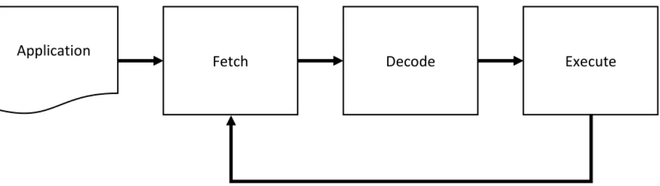
In an interpretive simulation of a processor model simulation happens in a loop, instructions are fetched, decode and executed one by one sequentially as show in figure 7. The target instruction is translated to host instructions or equivalent host-compiled functions to be executed on the host platform.
Figure 7 Interpretive ISS simulation flow
Interpretive ISS might be the most flexible approach but is also one of the slowest approaches due to it sequential nature of evaluation of each instruction. SimpleScalar [20] is such an example of an interpretive ISS, The sim-outorder tool is the lowest abstraction level in the toolkit which provides a cycle-accurate model of a processor. The simulator has seen wide adoption by researchers but it seems that both development and support have slowed down significantly, the last update was more than two years ago at the time of this writing.
Gem5 [11] is another simulation framework that provides processor models at different abstraction levels including various architectures of cycle-accurate processors as shown in Table 1.
Application
22
Table 1 Comparison of full system cycle accurate simulators Reference Simulator Accuracy Supported processor
architecture Licence Dev/Support
WindRiver
[21] Simics
Functionally-accurate
Alpha, ARM, MIPS, PowerPC, SPARC and x86
Private Yes
Yourst [22] PTLsim Cycle-accurate X86 Open Yes
Austin et al.
[20] SimpleScalar Cycle-accurate
Alpha, ARM, PowerPC
and x86 Open No
Imperas[12] OVPSim Instruction-accurate
Open Cores Open RISC, ARM, Synopsys ARC, MIPS, PowerPC, Xilinx MicroBlaze and others
Open and Private Yes
Binkert et
al. [23] GEM5 Cycle-accurate
Alpha, ARM, x86, SPARC, PowerPC and MIPS
Open Yes
Note: Reprinted with permission from Accuracy Evaluation of GEM5 Simulator System Anastasiia Butko, Rafael Garibotti, Luciano Ost and Gilles Sassatelli
The major drawback of interpretive ISS is the extremely slow simulation speed, which results from intensive decode of target instruction at run-time; putting that in the context of a whole system platform, simulation is extensive but very time consuming at the cycle or instruction abstraction level.
2.3.1.2.
Statically Compiled ISS
Statically compiled instruction set simulators decode and translate the target binary at compile time and extract tracing information for instructions. This eliminates the fetch and decode step compared to interpretive ISS. However this approach may work for simple systems it falls short to account for branching and mutable code. This technique requires application code to be
23
completely available at compile time, which is often not the case for languages supporting dynamic runtimes.
2.3.1.3.
Dynamically Compiled ISS
Dynamically compiled ISS overcome the limitations of statically compiled ISS by dynamically translating or retargeting target instructions into host instructions. Instructions are translated in to simpler micro operations which are usually precompiled for the host platform which the target architecture is running on.
QEMU is such an emulator that achieves this via binary translation (or binary retranslation) [24]. This allows QEMU to run unmodified target operating systems. QEMU alone provides only virtualization and emulation features for CPUs, which allows functional simulation and application development, but it however does not consider timing and impact of architecture layout on software execution. It is designed for speed: only a valid x86 API behavior must be reached, which means not necessarily with the right number of cycles or even in the same pipeline order.
D. Thach et al. [25] introduces a technique for cycle count estimation in QEMU via timing analysis of the pipeline. It has two passes first it statically calculates pipeline timing prior to simulation and at run-time it uses that data to account for branch prediction/divergence. The authors report results for an ARM processor a 26% simulation error rate against an average of 10% to actual hardware implementation. They also report a slow down by a factor of 3.37 times compared against an equivalent QEMU functional simulation.
OVPSim [12] is another simulation tool offered by Imperas Software that includes a large number of functional model of processors like ARM, Xilinx Micro blaze, MIPS, Power PC. It allows
24
simulation of these multiprocessor platforms containing arbitrary local and shared-memory topologies.
OVPSim implements its virtual platforms which run cross compiled programs on a semi-host dynamic linked library which does the dynamic binary translation of the cross-compiled application binary translating target instructions into x86 instructions on the host machine. The processor models provided are instruction-accurate.
2.3.2.
Host Compiled Simulation
Virtual platforms categorized as host compiled simulations are usually models at high levels of abstractions which allow them to provide fast evaluation but rely on coarse-grain estimation or worst-case static analysis.
Host compiled models typically start at the algorithmic level and are then modularly decomposed to the underlying hardware structure. [26] It is at this abstraction level that subsystems are defined and fleshed out to identify internal functions and the relations between them. Figure 8 shows the design process from high-levels abstraction to the gate level.
Fundamental decisions about the
25
processors, algorithm characteristics, memory architecture, data connections, software stack which shape the eventual implementation of the target design. Communication between subsystems can be represented by functions calls or at the transaction level between sub-systems, these transactions can be loosely timed for granular timing and performance exploration. Modelling at the transaction level allows models of different abstraction levels to co-exist in a single simualtion which allows more flexible IP resue and faster simulation by refinment of only “intersting” details.
Most models at these abstraction levels are for early design space exploration and application development with functional validation. At these levels processors are modelled as just modules with application threads which execute natively on the host and it is this native execution that gives host-compiled simulations the speedup over cycle-accurate simulations. Although good for functional validation they however do not directly allow performance estimation of the application on the target as only transactions between modules is modelled. To model the execution of host application code it is usually annotated. Tools like LLVM allow intermediate passes on compiled IR code to allow back annotation of statically determined low-level timing estimates. This still allows for fast simulation speed but improves the quality of the simulation as now application behaviour effects simulation timing. The limitation of Host-Compiled simulations is that unlike ISS they do not capture memory transactions as execution is directly on the host. This results in incorrect modelling semantics for applications which are heavily memory IO bound.
Given how integrated todays systems on chip are, they are no longer a simple dumb cluster of RISC processors or single beefy VLIW processors, functions are offloaded to a variety of optimized co-processors for faster and power efficient computation and all of these modules must work in tandem with each other to function. Full-blown simulation for a complete system at the cycle level would be too slow and in most cases is not possible because for most modules cycle
26
level simulators don’t exist (think base-band processors, cryptographic AISC key hashers, etc.), since most of these modules start as high-level algorithms, which are eventually implemented in hardware. To quickly evaluate and make decisions host-compiled simulations allow full system simulation with speed and relative accuracy.
2.4.
Summary
In this section we covered various implementations of forwarding planes from fully virtualized switches like soft-switches to high-speed low latency processing approaches for packet processing using distributed architectures like Network Processing Units or heavily pipelined architectures like RMT. Each platform makes its trade-offs between implementation complexity and application flexibility.
Next we took a look at simulation methodologies, instruction set simulation although the most detailed approach also has the most expensive modelling effort compared to Host compiled simulations which greatly inhibits the use of ISS as it does not offer the flexibility to evaluate different variations of models for comparative analysis needed to evaluate hardware design choices. Also due the extensive depth of simulation application development is unfeasible on ISS even with adaptive dynamic binary translation which sacrifices accuracy of simulation for speed. In the next section we will be taking a look at how different forwarding elements can be modelled and aim to solve some of the challenges of host-compiled simulations.
27
Chapter 3:
Modelling Forwarding Architectures
We use SystemC [10] and TLM [11] to model a host-compiled model of the hardware and the low-level software services of the forwarding device. The logic for the modules in the forwarding device is written in C++ by the user. The packet processing program to be executed by the programmable cores in the forwarding device is compiled from a P4 description and linked with the SystemC model of the forwarding device.
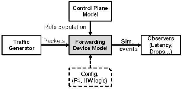
Figure 9 Simulation Environment
The control plane model populates the memories in the forwarding device model with match-table rule entries. The final executable SystemC model is stimulated by a traffic generator that feeds the model with a simulated stream of incoming packets. At run time, the model generates simulation events that are processed by user defined observers to derive metrics such as packet latency, drops, and energy consumption as shown in figure 9.
28
3.1.
Transaction-level Modeling in SystemC
SystemC is a widely used language for System-on-Chip design and validation. It is essentially a discrete event simulation library in C++ that provides modeling abstractions for system-level design. Transaction Level Modelling (TLM) is a modelling standard from OSCI [27]. TLM in SystemC enables creation of abstract hardware models, particularly of memories, for high speed co-simulation of hardware and embedded software. TLMs abstract away cycle-accuracy and bit-level accuracy using abstract function calls to access memories or hardware services.
In RTL, simulation is synchronized based on a clock. In a TLM, this “synchronization” takes place when data is exchanged between two modules, which means a clock is no longer needed for simulation. All the processes, state changes, data movements, and calculations that occur in a particular model or between two units are known as transactions. Since this transaction represents the sum total of the processes that occurs in a system for it to take place it begins at a particular point in time and ends some time later. This bounds the time period in which the transaction takes place, thus introducing approximate timing to the system.
Transaction level models represent components as a set of concurrent, interactive processes that compute and characterize their behavior. The models thusly describe complex systems at a high level of abstraction. To separate communication from computation transactions are carried out over an abstract channel, the definitions of these channels is standardized in TLM [28] but the implementations are carried out by the designer, this allows interoperability and reuse of models as the interfaces remain the same for components modelled in TLM. For faster simulation speeds, we can move to higher level transactional level models which have minimal details. These models can be improved over time or swapped with detailed models for more accurate simulation.
29
3.1.1.
TLM timing annotations
Since TLM transactions represent the sum of the activity in a model needed to carry out that transaction. TLM presents us with the following abstraction levels:
Untimed
This is the programmers view, components are modelled as processes and the transactions between components are represented using function calls. This allows functional validation but does not give any performance estimation of the architecture.
Loosely timed
This builds upon the untimed model, each transaction still completes in one function call. Timing is introduced by just two points, the start and the end. Transactions can also be temporally decoupled by letting process run ahead of simulation time in this case as shown in figure 10. The collective time is consumed at the end of all transactions which speeds simulation since it runs ahead of the master simulation clock. The standard also allows transactions to bypass the transaction-based block-to-block interface entirely and have direct access to areas of memory within a target function, again to accelerate simulation.
30
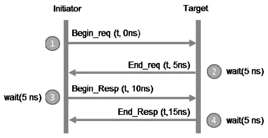
Approximately timed
AT attempts to achieve cycle-count-accuracy by annotating each step in the transaction as shown in figure 11. Each transaction is represented at the minimum by 4 timing points. More timing points can be added for more accuracy. However this means that processes must run in lock step with the master simulation clock time. It achieves relative accuracy of cycle-accurate models but does not incur the overhead cost of simulation all wire and pins of the model.
Figure 11 TLM Approximate timing annotation points
3.1.2.
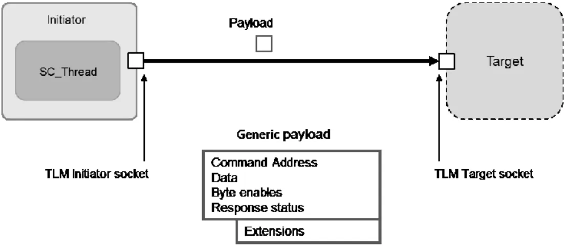
TLM Interfaces
TLM is all about interoperability of modules and get them talking to each other. In order to pass transactions between initiators and targets TLM provides the core interfaces for TLM sockets [28] as shown in figure 12. Initiators send transactions through initiator sockets, where targets receive them through target sockets. These sockets encapsulate communication between modules for both directions of communication. An initiator socket is implemented as a sc_port that is coupled with a sc_export on the side, whereas a target socket is a sc_export coupled with
31
a sc_port and we know a sc_export is actually encapsulating a sc_port with a sc_channel in it. The bind operator of the socket binds port-to-export and export-to port in a single function call. This allows the initiator and target to have bi-directional communication over the same socket and eliminates the need for implementing two separate channels for each direction. This convenience is a feature of sockets.
Figure 12 TLM Socket communication
The data sent over the subsequent link is carried in the TLM generic payload format, which already defines standard fields for data, addresses, commands, etc. These fields are information that is usually passed around in memory-mapped schemes as that TLM is geared toward providing interfaces for modelling busses and memory mapped systems.
Sockets already export a base protocol that handle the handshaking involved to send and acknowledge receipt of the payload by defining a set of points that mark the beginning and end of a request and a response. Just like the different timing notions these interfaces have different purposes.
32
3.1.2.1.
Blocking transport interface (b_transport)
Includes timing annotation.
Typically used with loosely-timed coding style.
Forward path only – Initiator is blocked until return form b_transport.
Allows direct memory access within the target function by passing a dmi pointer.
3.1.2.2.
Non-blocking transport interface (nb_transport)
Includes timing annotation and transaction phases.
Typically used with approximately-timed coding style
Called on forward and backward paths
Figure 13 illustrates the SystemC TLM representation of a simple design with a single processor core (core0) connected to memory (mem0). The application layer (applayer) and hardware abstraction layer (hal) are instantiated as sub-modules inside core0.
33
Threads inside the application layer use a port (hal_port) to access the memory read and write services provided by the hal module. The hal, in turn, implements these services via the memory interface ports (memory_if) that connect it to the TLM memory module (mem0) that implements the hardware memory services and maintains the memory state. The threads in the applayer execute natively on the host, resulting in much faster simulation than an interpretive instruction-set simulator.
3.2.
Modelling Memory
In our example above in section 3.2 we defined a communication element MEMORY which implements the memory_if interface, this interface defines functions for read and write as shown in listing 1.
Listing 1 Virtual functions declared by the memory interface 0: virtual void tx_read(tlm::tlm_generic_payload& trans)=0; 1: virtual void tx_write(tlm::tlm_generic_payload& trans)=0;
These functions accept a tlm transaction object which has fields for all of the information required for the transaction like virtual address, pointer to data on host memory and size of transaction. This Memory module (figure 14) provides the implementation for functions shown in listing 1.
For a module to read from an address in our memory module the initiator would simply call the read function of its interface which is connected to our CE and pass it a populated transaction object as shown in figure 14 with the target address and a hostpointer to an object that the CE should populate the value from the target address.
34
Figure 14 Memory CE interface
The function which is defined in the CE Memory would be called and it would execute its body shown in listing 2. The function accepts a TLM generic payload which has the memory address, a host pointer to return the data object, size of the transaction and command type. It performs address bounds checking to ensure a valid address and returns the value at the data pointer from its internal map of target addresses to host pointers. Similarly vice versa for the write operation except this time it also uses the transaction length to determine how many bytes to write from the address.
Listing 2 Memory CE implementation of the read function. 1: virtual void read(tlm::tlm_generic_payload& trans) {
2:
3: // check address range
4: if (!ValidateAddr(trans.get_address();)) { 5: RaiseError("Given transaction out of range:");
6: } 7:
8: if (trans.get_command() == tlm::TLM_READ_COMMAND ) { 9: trans.get_data_ptr() = mem.at(trans.get_address()); 10: // response status to indicate successful completion 11: trans.set_response_status(tlm::TLM_OK_RESPONSE); 12: } else {
13: trans.set_response_status(tlm::TLM_ERROR_RESPONSE); 14: }
35
Upon complete execution of the function control would be returned to the Initiator where we can consume the time taken for this transaction (temporal decoupling as discussed in section 3.1.1). The host data pointer in the transaction object now points to the object at the target address we read from. Since this module is a communication element we parameterize properties of the module like memory size, read and write latency to a configuration file. This parameterization allows us to model various types of memories like SRAM, edRAM, DRAM each having its own characteristics of read, write latency and maximum capacities.
3.3.
Modelling the Memory Controller
Traditionally memories are connected using shared busses or cross bars to processors but in distributed architectures like NPUs they employ networks on chip due to the fact that all of the distributed processing clusters have to talk to the same fixed-function modules. A memory by itself only understands addresses, conventionally these addresses are accessed by processors via the bus through an
arbitration mechanism. Shared busses don’t scale for processing cores inside clusters all of which need variable non-sequential access to the memories.
36
Also since each cluster has the same copy of the lookup data structures in their memories a distributed method for building these data structures in each cluster is needed. This is why the memories need to be connected to the on-chip network employed in the NPU. However the memory module cannot by itself directly connect with the on-chip network as it does not have the necessary interface.
Memory Controllers are the bridges between the two different set of interfaces. They are modeled as Processing Elements as they are active components that service requests from the on chip network interfaces queueRdI and queueWrI. The memory controller carries out the transactions to the memory over its memory_if interface by converting the received request to tlm_generic_payload objects which the CE memory module can understand.
Figure 16 Memory PE
Memory Controllers handle requests from modules for retrieving or storing packet payloads at an address or just general read/writes for lookup tables stored in memory. To allow for faster simulation we temporally decouple memory transaction to the memory CE instance tlm_memory by consuming time after the transaction call has finished in the PE Memory Controller. In this case the memory module itself becomes a hierarchal PE for wrapping the whole module. This memory PE forms the basic block for the memory architecture of the NPU model.
37
3.4.
Modelling Fixed Function Modules
Modules like Parsers, Routers and Schedulers are fixed function modules as they are solely implemented as dedicated hardware. The logic of these different modules is described simply in C++ which is executed in a systemc thread. The design pattern for describing the behaviour of modules is to have separate reader and writer threads as shown in figure 17 with internal buffers for storing/servicing transactions.
Figure 17 Design Pattern for fixed function modules
Modelling concurrency and concurrent behaviour can be tricky and often not so straight forward. Module behaviour modelled as single threads can often lead to modeling incorrect behaviour e.g. they can miss transactions on their interfaces which they may not in real life if they are stuck processing or waiting on another resource and such behaviour may only appear under certain test conditions which would make the model less robust in terms of modelling accuracy.
38
To solve this a systemc thread consumes these transactions from the input interfaces and places them in internal buffers.
Whereas another separate systemc threads models the actual behaviour of what the module performs on these transactions (functionality of the module). The port servicer thread initiates a systemc event notification every time it places a transaction in the buffer. The Functionality thread waits on this event notification when idle to resume processing by picking data from the internal buffer.
Figure 18 Behavioural design of fixed function modules
This avoids the design pitfall of putting all functionality in a single thread, as we now control the rate of servicing input ports in the port servicer thread by adjusting the size of the internal buffer. If the buffer is full then the port servicer thread can just drop the transaction or simply let the transactions accumulate at the link/queue (if the link models blocking to model
39
congestion) that the interface is connected to. The two thread design is the simplest example and scales very nicely in terms of having multiple processing threads.
3.5.
Soft switch Model Semantics
The soft switch is a virtualized switch as discussed in chapter 2, and has the simplest modelling semantic. The softswtich is modelled as a simple module with the application executing inside the module in a single SC_Thread. The module has two ports one for input and output which the soft switch uses to process packets.
The soft switch model has no timing semantics and executes natively on the host in the SC_Thread, its traces are used to determine functional validation of other architectural models.
3.6.
NPU Model Semantics
Our NPU model design deploys a distributed packet processing pipeline with a stream of input packets being read by the splitter module, which splits the headers from the payload and generates a packet descriptor representing the unparsed headers, this is sent to the parser over the OCN. The payload is dispatched to the requisite memory allocated by the memory manager. Parser parses the packet headers and populates the fields in the packet descriptor. Retargeted code from the P4 behavioral model is used by the parser to fill out the packet descriptor. It returns the number of states it took to parse the headers which is used to model single cycle latency for each parsed header. The parser dispatches the packet descriptor to the Global scheduler. The Scheduler deploys a FIFO pull model. Processing clusters request jobs from the Global scheduler which it services by forwarding packet descriptors to the cluster for processing.
40
The current design employs 8 processing clusters. Each processing cluster is comprised of 4 memory modules which represent the on-chip memory of the system and 8 processing cores which are 4 way threaded. The processing cores are managed by a cluster scheduler, which pulls processing requests from the global scheduler and assigns them in a round robin fashion to the processing clusters. The application executes inside the Processors as shown in figure 15 in SC_Threads. Data structures for longest and exact match lookups are populated for each cluster on the chip memory and spill over into a singleton memory module which represents the off chip memory in an NPU.
Due to the concurrent nature of processing any two packets being processed in the cluster on different cores, may encounter different delays due to lookups from the FIB in the memory and may leave the processing clusters in a different order than the one they arrived in. The order of packets is important for certain applications like in TCP under worst-case scenarios it would cause incessant retransmissions from the end nodes. Therefore, a reorder module is used to restore the ordering of packets. The traffic manager shapes packet flows according to their priority. Traffic managers are typically implemented as fixed-function units and consists of large banks of queues for quick-allocation and re-circulation. Deparser reconstitutes the packet with its processed headers and payload and sends it to the egress port where a SERDES module encapsulates it into to the egress data-link format.
3.7.
RMT Model Semantics
The RMT model is based on the forwarding architecture proposed in [5]. It is composed of three top level sub modules: the ingress and egress pipelines, and the queues in between them as
![Figure 3 Virtualizing switches embedded in Hypervisors [41]](https://thumb-us.123doks.com/thumbv2/123dok_us/10175805.2919896/24.918.412.814.442.680/figure-virtualizing-switches-embedded-hypervisors.webp)