Tensor coding for CDMA-MIMO wireless
communication systems
G´
erard Favier, Michele Da Costa, Andr´
e De Almeida, Jo˜
ao Romano
To cite this version:
G´
erard Favier, Michele Da Costa, Andr´
e De Almeida, Jo˜
ao Romano. Tensor coding for
CDMA-MIMO wireless communication systems. 19th European Signal Processing Conference
(EU-SIPCO), Aug 2011, Barcelone, Spain. 4 p., 2011.
<
hal-00718397
>
HAL Id: hal-00718397
https://hal.archives-ouvertes.fr/hal-00718397
Submitted on 16 Jul 2012
HAL
is a multi-disciplinary open access
archive for the deposit and dissemination of
sci-entific research documents, whether they are
pub-lished or not.
The documents may come from
teaching and research institutions in France or
abroad, or from public or private research centers.
L’archive ouverte pluridisciplinaire
HAL
, est
destin´
ee au d´
epˆ
ot et `
a la diffusion de documents
scientifiques de niveau recherche, publi´
es ou non,
´
emanant des ´
etablissements d’enseignement et de
recherche fran¸cais ou ´
etrangers, des laboratoires
publics ou priv´
es.
TENSOR CODING FOR CDMA-MIMO WIRELESS COMMUNICATION SYSTEMS
G´erard Favier
a, Michele N. da Costa
a,b, Andr´e L.F. de Almeida
c, Jo˜ao Marcos T. Romano
b aI3S Laboratory, University of Nice-Sophia Antipolis, CNRS, Sophia Antipolis, FrancebDSPCom Laboratory, University of Campinas (UNICAMP), Campinas, Brazil cDepartment of Teleinformatics Engineering, Federal University of Cear´a, Fortaleza, Brazil
[email protected] (G. Favier), [email protected] (M.N. da Costa), [email protected] (A.L.F. de Almeida), [email protected] (J.M.T. Romano)
ABSTRACT
In this paper, we propose a tridimensional tensor coding for multiple-input multiple-output (MIMO) communication sys-tems. This coding allows spreading and multiplexing the transmitted symbols in both space and time domains, owing the use of two allocation matrices. Assuming flat Rayleigh fading channels, the signals received byKreceive antennas duringPtime blocks, composed ofNsymbol periods each, withJchips per symbol, form a fourth-order tensor that satis-fies a new constrained tensor model. A two-step alternating least squares (ALS) algorithm is proposed for blindly and jointly estimating the channel and the transmitted symbols. The performance of the proposed blind receiver is evaluated by means of computer simulations.
1. INTRODUCTION
The key idea for improving the error performance in wireless communication systems is to jointly exploit several diversi-ties, which means redundancy into the information-bearing signals available at the receiver. This redundancy can be obtained through spreading operations at the transmitter, in space, time and/or frequency domains.
Generally speaking, space diversity results from the use of multiple antennas at both transmitter and receiver ends, which leads to multiple-input multiple-output (MIMO) chnels. As now well known, the deployment of multiple an-tennas in wireless systems allows improving the transmis-sion rate and reliability over single-transmit antenna systems, while keeping the same transmission bandwidth and power.
Space spreading results from the use of several transmit antennas for transmitting the same symbol or data stream, whereas time spreading consists in repeating the same sym-bol multiplied by spreading codes, during several chip pe-riods associated with each symbol. Time spreading can also be obtained by transmitting the same symbols or data streams over multiple blocks, each symbol period corresponding to a single channel use.
On the other hand, space multiplexing that consists in transmitting independent data streams in parallel on multiple antennas, allows to increase the transmission rate.
Space-time (ST) coding is one of the most popular ap-proaches relying on multi-antenna transmissions for achiev-ing the fundamental tradeoff between error performance (in terms of bit error rate, abbreviated as BER) and data rate (in bits per channel use) [10].
Since the pioneering work of [9], several tensorial ap-proaches have been developed for space-time MIMO
wire-This work is supported by the CAPES-COFECUB project No. Ma 544/07. Andr´e L. F. de Almeida is partially supported by CNPq/Brazil (Grant No. 303238/2010-0).
less communication systems with matrix ST coding and blind receivers [1, 2, 3, 4, 5, 6, 8].
In this paper, we propose a new tensor space-time (TST) coding. This TST coding allows spreading and multiplex-ing the transmitted symbols in both space (transmit anten-nas) and time (chips and blocks) domains, through the use of a third-order code tensor admitting transmit antenna, data stream and chip as modes, and two allocation matrices that allocate transmit antennas and data streams to each block. Assuming flat Rayleigh fading propagation channels, the sig-nals received by K receive antennas duringP time blocks, composed ofNsymbol periods each, withJchips per sym-bol, form a fourth-order tensor that satisfies a new con-strained tensor model, called a PARATUCK-(2,4) model. The proposed transmission system can be viewed as an ex-tension of the ST transmission system of [4] that relies on a PARATUCK-2 tensor model for the received signals. This extension results from the introduction of a time-spreading code. Then, a blind TST-based receiver is derived for joint channel and symbol estimation using a two-step alternating least squares (ALS) algorithm.
The rest of the paper is organized as follows. Section 2 presents the proposed MIMO transmission system using a TST coding. The tensor of received signals is then derived assuming flat Rayleigh fading propagation channels. Section 3 discusses the identifiability and uniqueness conditions for the PARATUCK-(2,4) model of the received signals, and a blind TST-ALS based receiver is proposed for joint channel and symbol estimation. In Section 4, some simulation results are provided to illustrate the performance of this receiver, before concluding the paper in Section 5.
Notations:Scalars, column vectors, matrices and higher-order tensors are written as lower-case (a, b,...), bold-face lower-case (a, b,...), boldface upper-case (A, B,...),
and blackboard (A, B,...) letters, respectively. AT, AH,
A∗, andA†stand for transpose, transconjugate (Hermitian
transpose), complex conjugate, and Moore-Penrose pseudo-inverse ofA, respectively. The vectorAi·(resp.A·j)
repre-sents theithrow (resp. jthcolumn) ofA. The scalarai1,···,iN
denotes the (i1,· · ·,iN)-th entry ofA.Di(A)is the diagonal
matrix formed with theithrow ofA; I
N is the identity
ma-trix of orderN,1Nis the all-one column vector of dimension
(N,1), andk·kFis the Frobenius norm. The operator vec(·)
forms a vector by stacking the columns of its matrix argu-ment, whereas diag(·)forms a diagonal matrix from its vec-tor argument. The Kronecker and Khatri-Rao (column-wise Kronecker) products are denoted by⊗and♦, respectively. We have the following property:
forA∈CI×R,B∈CJ×SandC∈CS×R.
2. TENSOR CODING AND TENSOR MODELING OF RECEIVED SIGNALS
2.1 Proposed TST coding
We consider a MIMO wireless communication system with
Mtransmit antennas andKreceive antennas, and we denote bysn,rthenthsymbol of therthdata stream, each data stream
being composed ofNinformation symbols.
The transmission is assumed to be decomposed into P
data blocks, each block being formed ofNtime slots. At each time slotnof thepthblock, the transceiver transmits a linear combination of the nth symbols of the data streams deter-mined by the stream-to-block allocation matrixΨ∈RP×R, across a set of transmit antennas fixed by the antenna-to-block allocation matrixΦ∈RP×M.
Each symbolsn,ris replicated several times after
multipli-cation by a three-dimensional spreading codewm,r,j, in such
a way that the signal transmitted from themth transmit an-tenna during thenthtime slot of thepthblock, and associated with the jthchip, is given by:
um,n,p,j= R
∑
r=1 wm,r,jsn,rφp,mψp,r= R∑
r=1 gm,r,p,jsn,r (2) with gm,r,p,j=wm,r,jφp,mψp,r (3) Remark:ψp,r=1 means that therthdata stream is allocatedto the pth block, whereasψp,r=0 means that the rth data
stream is not allocated to the pthblock.
2.2 Tensor modeling of received signals
In the noiseless case and assuming flat Rayleigh fading propagation channels, the discrete-time baseband-equivalent model for the signal received at thekthreceive antenna dur-ing the jth chip period of the nth symbol period of the pth
block, is given by:
xk,n,p,j= M
∑
m=1 hk,mum,n,p,j= M∑
m=1 R∑
r=1 gm,r,p,jhk,msn,r (4)The fading coefficientshk,m between transmit antennas
(m) and receive antennas (k) are assumed to be independent and identically distributed (i.i.d.) zero-mean complex Gaus-sian random variables. They are also assumed to be constant during at leastPblocks.
The fourth-order tensorX∈CK×N×P×Jof received
sig-nals satisfies the constrained tensor model (3)-(4) that we will call a PARATUCK-(2,4) model.
Remark:If we setJ=1, (2) becomes independent of j:
um,n,p= R
∑
r=1
wm,rsn,rφp,mψp,r (5)
which corresponds to the ST transmission system proposed in [4] that leads to a PARATUCK-2 model for the received signals.
Comparing (5) with (2), we can conclude that the pro-posed TST coding allows to take a supplementary time di-versity into account. This didi-versity is associated with the
third mode (j) of the code tensor that induces an extra time-spreading of the symbols. Note that the transmission rate for both transceivers is given byV =RPlog2(µ)bits per
chan-nel use, whereµis the cardinality of the information symbol constellation.
3. BLIND TST-BASED RECEIVER
3.1 Matrix representations of the received signal tensor Let us define X··p,j∈CK×N as the matrix slice of the re-ceived signal tensorX∈CK×N×P×J, obtained by slicing it
along the plane (p,j), i.e. by fixing the two last indices. Us-ing (4) leads to the followUs-ing factorization
X··p,j=H G··p,jST (6)
whereG··p,j∈CM×Rcan be deduced from (3)
G··p,j=Dp(Φ)W··jDp(Ψ) (7)
Applying property (1) to (6) and (7) gives
vec X··p,j = (S⊗H)vec G··p,j (8) and vec G··p,j = Dp(Ψ)⊗Dp(Φ) vec W··j (9) =diag vec W··j ΨTp·⊗ΦTp· (10) which gives
vec X··p,j= (S⊗H)diag vec W··j ΨTp·⊗ΦTp· (11)
From (6), we deduce the following two matrix unfoldings of the received signal tensorX:
X2= X··1,1 .. . X··P,1 .. . X··1,J .. . X··P,J ∈CPJK×N, X3= XT·· 1,1 .. . XT·· P,1 .. . XT ··1,J .. . XT·· P,J ∈CPJN×K, = (IPJ⊗H)G2ST = (IPJ⊗S)G3HT (12) with G2= G··1,1 .. . G··P,1 .. . G··1,J .. . G··P,J ∈CPJM×R, G3= GT ··1,1 .. . GT·· P,1 .. . GT ··1,J .. . GT·· P,J ∈CPJR×M. (13)
Using (11), we can build a third matrix unfolding ofXas:
X1= [ vec(X··1,1) · · · vec(X··P,1) · · · vec(X··P,J) ]
= (S⊗H)G1∈CNK×JP (14) where G1=[diag(vec(W··1)) ΨT♦ΦT · · · · · ·diag(vec(W··J)) ΨT♦ΦT ] ∈CRM×JP (15)
3.2 Identifiability and uniqueness issues
Structure of the third-order code tensorW∈CM×R×J
For the code tensor, we choose a third-order Vander-monde tensor defined as:
wm,r,j=ei2πmr j/MRJ, (16)
wherei2=−1. An important reason behind this choice for the code tensor is that this Vandermonde structure guarantees the existence of a minimum value of the spreading length J ensuring the identifiability in the LS sense of the channel (H)
and symbol (S) matrices whenM6=R. Due to a lack of space, this result can not be developed in this paper.
Proceeding in the same way as in [4], it is easy to deduce the following results.
Identifiability
Each matrixSandH is estimated by alternately
solv-ing the two equations (12) in the LS sense with respect to one matrix conditionally to the knowledge of previously es-timated value of the other matrix. Assuming that the sym-bol and channel matrices are full column-rank, which implies
N≥RandK≥M, uniqueness of their conditional LS esti-mates requires thatG2∈CPJM×RandG
3∈CPJR×Mbe also
full column-rank. From this double condition, we deduce the following theorem.
Theorem 1. Assuming thatSandHare full column-rank, a necessary condition for identifiability is given by:
PJ≥max R M, M R . (17)
where⌈x⌉denotes the smallest integer number greater than or equal to x.
This condition (17) defines a constraint that the design parameters (P,J,M,R) must satisfy. It is interesting to no-tice that the supplementary diversity introduced by the time-spreading mode (j) of the code tensor allows us to get a more relaxed condition on the numberPof data blocks that is nec-essary for LS identifiability.
Theorem 2. Assuming thatSandHare full column-rank, and choosing a Vandermonde code tensor as defined in(16)
and the allocation matrices such thatΦp·=1T
M andΨp·= 1T
R, for a given p∈ {1, ...,P}, thenSandHare identifiable in the LS sense if M=R, for all values J≥1.
This sufficient condition is identical to that of Theorem 2 in [4] obtained forJ=1. However, unlike [4], introducing the time-spreading mode in the Vandermonde code tensor al-lows to derive a minimum value of the spreading lengthJ
that ensures the identifiability ofSandHin the caseM6=R.
Uniqueness
Theorem 3. IfΨT♦ΦTis full row-rank, which implies P≥
RM, thenSandHare unique up to a scalar factor, i.e.
S=αˆS, H= 1 α
ˆ
H. (18)
This theorem is identical to theorem 3 of [4], which means that the introduction of the time-spreading mode in the code tensor does not modify the uniqueness property of the tensor model. The scaling ambiguityαcan be eliminated in assuming known the first transmitted symbols1,1.
3.3 ALS algorithm for blind joint symbol and channel estimation
Assuming that the code tensorWand the allocation matrices
Φ andΨ are known at the receiver, the matrices G2 and G3can be pre-calculated. Blind joint symbol and channel
estimation can be carried out by applying the ALS technique for solving the two equations (12) with respect toSandH,
respectively.
4. SIMULATION RESULTS
The performance of the proposed TST coding and the as-sociated ALS-based blind receiver is evaluated by means of Monte Carlo simulations, in terms of BER and normalized mean square error (NMSE) on channel estimation, defined as NMSEdB=10 log10 1 L L
∑
l=1 kH−Hˆ l(∞)k 2 F kHk2F , (19)whereHˆl(∞)is the channel matrix estimated at convergence
of the lth run, andL=2000 is the total number of Monte Carlo runs corresponding to 2000 random wireless chan-nels, with different symbol sequences randomly drawn from a QPSK constellation, and different additive random noise sequences, for each simulated channel. A different random initialization Hˆl(0) is also used for each run. The BER is
calculated by averaging the results obtained for theR data streams and theLMonte Carlo runs. The signal-to-noise ra-tio (SNR) is determined by SNR=10 log10kX2k 2 F kV2k2 F , (20)
whereV2is the unfolded matrix of the additive noise tensor.
The default values of the tuning parameters are chosen as follows:R=2,N=10,J=3,P=4,K=M=2.
ForP=10,M=2 andR=4, the allocation matrices are chosen such as:
Φ10= 1 1 0 1 1 1 1 0 1 1 0 1 1 1 0 1 1 0 1 0 , Ψ10= 1 1 1 1 1 0 0 1 0 1 1 1 0 1 0 0 1 0 1 0 0 1 0 1 1 1 0 1 1 0 0 1 0 1 1 1 1 1 1 0 . (21)
The matricesΦ4 andΨ4forM=2 andR=4 are
ob-tained by discarding the last six rows ofΦ10andΨ10given
in (21), respectively. In the same way, the matrix Ψ10 for
R=2 is obtained by discarding the last two columns ofΨ10
forR=4. Use of the default values (P=4,R=2) implies a transmission rate equal to 1 bit per channel use.
In the sequel, we study the influence of the spreading code length (J), and of the numbers of blocks (P) and data streams (R). Then, we compare the proposed TST cod-ing with the KRST codcod-ing of [8], and a comparison is also made with the zero-forcing (ZF) receiver assuming a perfect knowledge of the channel matrix.
4.1 Influence of the spreading code length
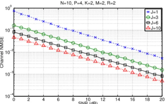
Figures 1, 2 and 3 show the channel NMSE, the BER and the number of iterations needed for convergence, versus SNR, for four values of the spreading code length (J ∈ {1,3,6,10}), respectively. From Figures 1 and 2, we can conclude that an increase ofJinduces a significant perfor-mance improvement in terms of both channel estimation and symbol recovery. Moreover, the use ofJ>1 implies a faster convergence comparatively to the one obtained with J=1 (see Figure 3). This improvement is due to the fact that the extra time-spreading introduced by the TST coding provides more output measurements to estimate the same number of parameters, which makes the convergence faster. It is to be recalled that the caseJ=1 corresponds to the blind receiver proposed in [4].
4.2 Influence of the block and data stream numbers
In order to emphasize the importance of time-spreading in the proposed TST coding, we analyze the BER for two val-ues of the block number (P∈ {4,10}), of the spreading code length (J∈ {1,3}) and of the data stream number (R∈ {2,4}) with the allocation matrices given in (21).
0 2 4 6 8 10 12 14 16 18 20 10−4 10−3 10−2 10−1 100 N=10, P=4, K=2, M=2, R=2 Channel NMSE SNR (dB) J=1 J=3 J=6 J=10
Figure 1: Influence of J: ChannelNMSEversusSNR.
0 2 4 6 8 10 12 14 16 18 20 10−5 10−4 10−3 10−2 10−1 100 N=10, P=4, K=2, M=2, R=2 BER SNR (dB) PARATUCK−2,J=1 PARATUCK−(2,4),J=3 PARATUCK−(2,4),J=6 PARATUCK−(2,4),J=10 PARATUCK−KRST
Figure 2: Influence of J:BERversusSNR.
0 2 4 6 8 10 12 14 16 18 20 0 5 10 15 20 25 N=10, P=4, K=2, M=2, R=2 Number of iterations SNR (dB) PARATUCK−2,J=1 PARATUCK−(2,4),J=3 PARATUCK−(2,4),J=6 PARATUCK−(2,4),J=10 PARATUCK−KRST
Figure 3: Influence of J: Iteration number for convergence versusSNR.
4.2.1 Spreading code length versus block number
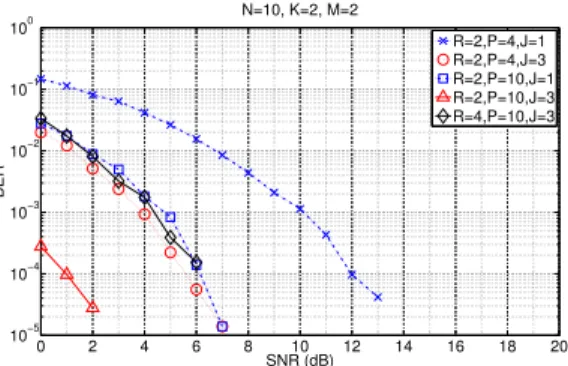
In Figure 4, we note that the BER performance can be sig-nificantly improved by increasing either the number of data blocks or the spreading code length, since both actions in-duce an increase of time diversity. Remark that, forR=2, when using J=1, a larger number of blocks (P=10) is needed to obtain nearly the same BER as the one obtained withJ=3 andP=4. However, forR=2, when the number of blocks is increased from 4 to 10, the transmission rate is reduced from 1 to 2/5 bit per channel use.
4.2.2 Spreading code length versus data stream number
ForP=10, the transmission rate is equal to 2/5 and 4/5 bit per channel use whenR=2 andR=4, respectively. As ex-pected and as shown in Figure 4, the BER performance is improved when the number of data streams is reduced from 4 to 2 (forP=10 andJ=3), which implies fewer symbols to be estimated with the same number of received signals. That illustrates the tradeoff to be achieved between error per-formance and transmission rate. It is very interesting to note that, forP=10, the error performance forJ=1 andR=2 is close to the one obtained withJ=3 andR=4, which shows that the use of TST coding allows to double the transmission rate without modifying much the BER.
4.3 Comparison with the KRST coding and the non-blind ZF receiver
The proposed blind TST-ALS based receiver is now com-pared with the non-blind TST-ZF receiver that estimates the symbol matrix by means of the following formula ˆST
ZF= [(IPJ⊗H)G2]†X˜2.
0 2 4 6 8 10 12 14 16 18 20 10−5 10−4 10−3 10−2 10−1 100 N=10, K=2, M=2 BER SNR (dB) R=2,P=4,J=1 R=2,P=4,J=3 R=2,P=10,J=1 R=2,P=10,J=3 R=4,P=10,J=3
Figure 4: Influence of P and R:BERversusSNR.
0 2 4 6 8 10 12 14 16 18 20 10−5 10−4 10−3 10−2 10−1 100 N=10, P=4, K=2, M=2, R=2 BER SNR (dB) ALS J=1 ALS J=3 ZF J=1 ZF J=3
Figure 5: Comparison ofTST-ALSandTST-ZFreceivers.
For this comparison, the design parameters were set to their default values. The BER obtained with the two algo-rithms (ALS and ZF) is plotted on Figure 5 forJ∈ {1,3}. From these simulation results, we can conclude that, for a BER equal to 10−3 , the gap between the blind TST-ALS
and non-blind TST-ZF receivers is around 2.5 dB in terms of SNR, for both valuesJ=1 andJ=3.
The simulation results are also compared with those ob-tained with the blind KRST-ALS based receiver of [8], with an identity precoding matrix.
With KRST coding, only one data stream, composed of
M symbols, is transmitted from M transmit antennas, dur-ing each time blockpofNslots, using two coding matrices
W∈RM×M andC∈RN×M. The first one allows to
com-bineMsymbols onto each transmit antenna, for a given block
p, which gives the pre-coded signalvp,m= M
∑
l=1
wm,lsp,l. The second matrix is to spread such a combination transmitted by each antenna overN slots, which provides a third-order ten-sor for the transmitted signals defined asum,n,p=vp,mcn,m.
Observe that for KRST coding, the number of data streams is forced to be equal to the number of transmit anten-nas, while it can be chosen equal toR≥Mwith TST coding. In addition, the use of tensor coding instead of matrix-based pre- and post-coding presents the advantages of an extra time spreading on chip and not needing decoding at the receiver.
Figures 2 and 3 show that the proposed TST-ALS based receiver outperforms the KRST-ALS based receiver in terms of BER, at the cost of a slower convergence due to the greater number of parameters to be estimated (PNRsymbols for the TST coding andPMsymbols for the KRST coding).
5. CONCLUSION
In this paper, a new tensor space-time coding has been pro-posed for MIMO wireless communication systems. The as-sociated transceiver is characterized by a third-order code tensor and two allocation matrices that allow space-time spreading-multiplexing of the transmitted symbols. The in-troduction of one extra time diversity via the third mode of the code tensor induces a significant performance im-provement in terms of BER and channel estimation accuracy comparatively to our previous solution [4], as illustrated by means of simulation results. This extra time diversity leads to a more relaxed condition on the number of data blocks to be processed for ensuring LS identifiability of channel and symbol matrices that can be jointly and blindly estimated us-ing a two-step ALS technique. There are several perspec-tives of this work that include extensions to frequency se-lective and/or time varying MIMO channels [7], space-time-frequency coding, code design and allocation matrices opti-mization, alternative receiver algorithms, and blind receiver when the code tensor is unknown at the receiver.
REFERENCES
[1] A. L. F. de Almeida, G. Favier, and J. C. M. Mota. A constrained factor decomposition with application to mimo antenna systems. IEEE Transactions on Signal Processing, 56(6):2429–2442, 2008.
[2] A. L. F. de Almeida, G. Favier, and J. C. M. Mota. Con-strained tensor modeling approach to blind multiple-antenna cdma schemes. IEEE Transactions on Signal Processing, 56(6):2417–2428, 2008.
[3] A. L. F. de Almeida, G. Favier, and J. C. M. Mota. Mul-tiuser mimo system using block space-time spreading and tensor modeling. Signal Processing, 88(10):2388– 2402, 2008.
[4] A. L. F. de Almeida, G. Favier, and J. C. M. Mota. Space-time spreading-multiplexing for mimo wireless communication systems using the paratuck-2 tensor model.Signal Processing, 89(11):2103–2116, 2009. [5] A. de Baynast, L. de Lathauwer, and B. Aazhang. Blind
parafac receivers for multiple access-multiple antenna systems. InProc. IEEE 58th Fall Vehicular Technology Conf. (VTC 2003), volume 2, pages 1128–1132, 2003. [6] L. de Lathauwer and A. de Baynast. Blind
deconvo-lution of DS-CDMA signals by means of decomposi-tion in rank-(1,L,L) terms. IEEE Transactions on Sig-nal Processing, 56(4):1562–1571, 2008.
[7] D. Nion and N. D. Sidiropoulos. Adaptive algo-rithms to track the PARAFAC decomposition of a third-order tensor. IEEE Transactions on Signal Processing, 57(6):2299–2310, 2009.
[8] N. D. Sidiropoulos and R. S. Budampati. Khatri-rao space-time codes. IEEE Transactions on Signal Pro-cessing, 50(10):2396–2407, 2002.
[9] N. D. Sidiropoulos, G. B. Giannakis, and R. Bro. Blind parafac receivers for ds-cdma systems. IEEE Transac-tions on Signal Processing, 48(3):810–823, 2000. [10] L. Zheng and D. N. C. Tse. Diversity and
multi-plexing: a fundamental tradeoff in multiple-antenna channels. IEEE Transactions on Information Theory, 49(5):1073–1096, 2003.