Calhoun: The NPS Institutional Archive
Theses and Dissertations Thesis Collection
2013-09
Using model based systems engineering and the
systems modeling language to develop space
mission area architectures
Jepperson, Dustin B.
Monterey, California. Naval Postgraduate School
NAVAL
POSTGRADUATE
SCHOOL
MONTEREY, CALIFORNIA
THESIS
Approved for public release; distribution is unlimited
USING MODEL BASED SYSTEMS ENGINEERING AND THE SYSTEMS MODELING LANGUAGE TO DEVELOP
SPACE MISSION AREA ARCHITECTURES
by
Dustin B. Jepperson September 2013
Thesis Advisor: Mark Rhoades
REPORT DOCUMENTATION PAGE Form Approved OMB No. 0704-0188
Public reporting burden for this collection of information is estimated to average 1 hour per response, including the time for reviewing instruction, searching existing data sources, gathering and maintaining the data needed, and completing and reviewing the collection of information. Send comments regarding this burden estimate or any other aspect of this collection of information, including suggestions for reducing this burden, to Washington headquarters Services, Directorate for Information Operations and Reports, 1215 Jefferson Davis Highway, Suite 1204, Arlington, VA 22202-4302, and to the Office of Management and Budget, Paperwork Reduction Project (0704-0188) Washington DC 20503.
1. AGENCY USE ONLY (Leave blank) 2. REPORT DATE September 2013
3. REPORT TYPE AND DATES COVERED
Master’s Thesis
4. TITLE AND SUBTITLE
USING MODEL BASED SYSTEMS ENGINEERING AND THE SYSTEMS MODELING LANGUAGE TO DEVELOP SPACE MISSION AREA ARCHITECTURES
5. FUNDING NUMBERS
6. AUTHOR(S) Dustin B. Jepperson
7. PERFORMING ORGANIZATION NAME(S) AND ADDRESS(ES)
Naval Postgraduate School Monterey, CA 93943-5000
8. PERFORMING ORGANIZATION REPORT NUMBER
9. SPONSORING /MONITORING AGENCY NAME(S) AND ADDRESS(ES)
Los Angeles Air Force Base – Space and Missiles Systems Center 483 North Aviation Blvd
El Segundo CA 90245
10. SPONSORING/MONITORING AGENCY REPORT NUMBER
11. SUPPLEMENTARY NOTES The views expressed in this thesis are those of the author and do not reflect the official policy or position of the Department of Defense or the U.S. government. IRB protocol number _NPS.2013.0069_.
12a. DISTRIBUTION / AVAILABILITY STATEMENT Approved for public release;distribution is unlimited
12b. DISTRIBUTION CODE
A
13. ABSTRACT (maximum 200 words)
Model based systems engineering (MBSE) is explored as an alternative to the Department of Defense (DoD)’s heavily document-driven processes for architecture development and acquisition management. MBSE can be employed to meet the standards set in the DoD acquisition framework. Data exchange specifications, such as the application protocol 233 (AP233), can be implemented to enable synergistic benefits to data analysis across the enterprise. Architecture development techniques, including the structured analysis and design technique and the systems modeling language (SysML), are introduced to aid in the development and assessment of space system mission area architectures, enabling rigorous mathematical analysis to support key programmatic decisions. A detailed example of the application of SysML, in conjunction with MBSE principles, is provided for the Overhead Persistent Infrared mission area, specifically the Space Based Infrared Surveillance System. A three-phase adoption approach is recommended: first identify, list, and manage the configuration of all critical program models, processes, and tools used throughout the DoD. Second, mandate a data exchange specification, such as the International Organization for Standardization (10303 AP233 standard, across the DoD space acquisition community. Finally, further standardize the implementation of MBSE practices through implementation of SysML. Heuristics for developing system architecture are provided.
14. SUBJECT TERMS Model Based Systems Engineering (MBSE), Systems Modeling Language (SySML), Structured Analysis and Design Technique (SADT), Application Protocol 233 (AP233), Department of Defense Architecture Framework (DoDAF), Space Mission Area System Architecture (MASA), Overhead Persistent Infrared (OPIR), Space Based Infrared Surveillance System (SBIRS), System Architecture Heuristics
15. NUMBER OF PAGES 147 16. PRICE CODE 17. SECURITY CLASSIFICATION OF REPORT Unclassified 18. SECURITY CLASSIFICATION OF THIS PAGE Unclassified 19. SECURITY CLASSIFICATION OF ABSTRACT Unclassified 20. LIMITATION OF ABSTRACT UU
NSN 7540-01-280-5500 Standard Form 298 (Rev. 2-89)
Approved for public release; distribution is unlimited
USING MODEL BASED SYSTEMS ENGINEERING AND THE SYSTEMS MODELING LANGUAGE TO DEVELOP SPACE MISSION AREA
ARCHITECTURES
Dustin B. Jepperson Captain, United States Air Force B.S., University of Wisconsin, Madison, 2008
Submitted in partial fulfillment of the requirements for the degree of
MASTER OF SCIENCE IN SYSTEMS ENGINEERING MANAGEMENT
from the
NAVAL POSTGRADUATE SCHOOL September 2013
Author: Dustin B. Jepperson
Approved by: Mark Rhoades, PhD Thesis Advisor
Kristin Giammarco, PhD Second Reader
Clifford Whitcomb, PhD
ABSTRACT
Model based systems engineering (MBSE) is explored as an alternative to the Department of Defense (DoD)’s heavily document-driven processes for architecture development and acquisition management. MBSE can be employed to meet the standards set in the DoD acquisition framework. Data exchange specifications, such as the application protocol 233 (AP233), can be implemented to enable synergistic benefits to data analysis across the enterprise. Architecture development techniques, including the structured analysis and design technique and the systems modeling language (SysML), are introduced to aid in the development and assessment of space system mission area architectures, enabling rigorous mathematical analysis to support key programmatic decisions. A detailed example of the application of SysML, in conjunction with MBSE principles, is provided for the Overhead Persistent Infrared mission area, specifically the Space Based Infrared Surveillance System. A three-phase adoption approach is recommended: first identify, list, and manage the configuration of all critical program models, processes, and tools used throughout the DoD. Second, mandate a data exchange specification, such as the International Organization for Standardization (10303 AP233 standard, across the DoD space acquisition community. Finally, further standardize the implementation of MBSE practices through implementation of SysML. Heuristics for developing system architecture are provided.
TABLE OF CONTENTS
I. INTRODUCTION...1
A. PROBLEM STATEMENT AND OBJECTIVE ...1
B. RESEARCH QUESTIONS ...4
C. BENEFITS OF STUDY ...4
II. DOD ACQUISITION AND SYSTEMS ENGINEERING PROCESSES ...5
III. MODEL BASED SYSTEMS ENGINEERING AND THE SYSTEMS MODELING LANGUAGE FOR SYSTEMS ENGINEERING AND ARCHITECTURE DEVELOPMENT ...13
A. SYSTEM MODELS ...15
B. MODEL BASED SYSTEMS ENGINEERING...16
C. SYSTEM ARCHITECTURE DESIGN AND DEVELOPMENT ...19
D. WHY FOCUS ON SYSTEM ARCHITECTURE AND TRADE STUDIES? ...20
E. MODELING AND SIMULATION ...23
F. ANALYSIS OF ALTERNATIVES ...26
G. MBSE ARCHITECTURE TOOLS AND TECHNIQUES ...28
1. Department of Defense Architecture Framework (DoDAF) ...28
2. Structured Analysis and Design Technique ...30
3. Systems Modeling Language (SySML) ...36
a. History of SysML ...36
b. Overview of SysML ...37
c. SysML Purpose and Key Features ...40
d. SysML Support to Modeling and Simulation ...41
e. SysML Tools ...44
IV. CASE STUDY—OVERHEAD PERSISTENT INFRARED (OPIR) MISSION AREA ARCHITECTURE ...47
A. PURPOSE ...47
B. SCOPE ...47
C. PROBLEM SUMMARY ...47
D. SYSML DIAGRAMS...48
1. Internal Block Diagram—System Context ...49
2. Use Case Diagram—Top Level ...50
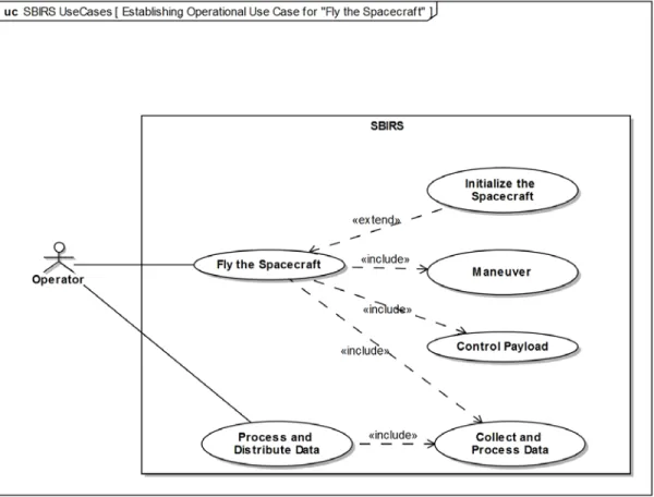
3. Use Case Diagram—Operational Level ...51
4. Sequence Diagram—Initialize Black Box ...52
5. State Machine Diagram—Spacecraft Operational States ...53
6. Decomposed Sequence Diagrams ...54
7. Requirements Diagrams ...56
8. Activity Diagrams ...59
9. Block Definition Diagrams ...63
V. IMPLEMENTATION OF MODEL BASED SYSTEMS ENGINEERING AND ENTERPRISE SYSTEMS ENGINEERING TECHNIQUES AT THE
SPACE AND MISSILES SYSTEM CENTER ...81
A. TRANSITIONING TO MBSE...81
B. DATA EXCHANGE SPECIFICATIONS ...82
C. SMC REQUIREMENTS AND CURRENT TOOLS...84
1. Current SMC Tools and Processes ...84
2. SMC Requirements ...86
D. POTENTIAL VALUE OF MBSE AND DATA EXCHANGE SPECIFICATION TO SMC ...88
E. BARRIERS AND LIMITATIONS ...90
VI. CONCLUSIONS AND RECOMMENDATIONS ...95
A. RESPONSE TO RESEARCH QUESTIONS ...95
1. What Methods, Techniques, and Processes can be Employed to Aid in the Development of Mission Area Architectures for Department of Defense (DoD) Space Systems? ...95
2. In What Ways or in What Instances Can Model Based Systems Engineering (MBSE) be Used in the Development of Space Based Mission Area Architectures for the DoD? ...95
3. How can the System Modeling Language (SysML), Based on the Common Software Engineering Unified Modeling Language (UML), be Applied to Aid in Developing Mission Area Architectures for DoD Space Systems? ...96
B. PROCESS DISCUSSION ...96
1. Discussion of the Iterative and Recursive Nature of the Synthesis Process ...96
2. Comments on the Use of MagicDraw ...97
C. CONCLUSIONS ...98 D. RECOMMENDATIONS ...98 1. Phase 1...99 2. Phase 2...99 3. Phase 3...100 E. FUTURE WORK ...100
APPENDIX. THE ART OF SYSTEM ARCHITECTURE—HEURISTICS ...103
1. Focus on User Interactions and Interfaces ...103
a. Discussion...103
2. Maximize Cohesion ...104
a. Discussion...105
3. Minimize Coupling...106
a. Discussion...106
4. Don’t Forget Implementation Planning ...107
a. Discussion...110
7. Maximize Alternatives ...111
a. Discussion...111
8. Use Prototypes to Refine Requirements ...112
a. Discussion...113
9. Iterative and Recursive...114
a. Discussion...114
10. Modular Design ...115
a. Discussion...115
LIST OF REFERENCES ...117
LIST OF FIGURES
Figure 1. Department of Defense System Acquisition Framework (From
Department of Defense 2008) ...5 Figure 2. Notional Emphasis of Systems Engineering Processes Throughout the
Defense Acquisition System Life Cycle (From Defense Acquisition University 2013e, Chapter 4) ...8 Figure 3. Department of Defense—Systems Engineering Technical Management
Processes (From Defense Acquisition University 2013f) ...9 Figure 4. Department of Defense—Defense Acquisition Management System
Technical “V” Activities (From Defense Acquisition University 2013f, Defense Acquisition Management System) ...9 Figure 5. “V” Model Highlighting Phasing and Relationships Between Systems
Engineering Activities Conducted Throughout the Materiel Solution Analysis Phase of the Defense Acquisition Framework (From Defense Acquisition University 2013j)...10 Figure 6. Strength of Correlation Between Various Systems Engineering
Capabilities/Drivers and Overall Project Performance (From Elm and Goldenson 2012, Executive Summary) ...21 Figure 7. Mosaic Chart Comparing Various Level of SEC-ARCH to Overall Project
Performance (From Elm and Goldenson 2012, 35) ...22 Figure 8. Mosaic Chart Comparing Various Level of SEC-TRD to Overall Project
Performance (From Elm and Goldenson 2012, 38) ...23 Figure 9. Benefits of Using Modeling and Simulation Throughout the Acquisition
Life Cycle (From Defense Acquisition University 2013c, 4.3.19.1) ...24 Figure 10. Various Applications of Modeling and Simulation Across the DoD
Acquisition Framework (From Defense Acquisition University 2013c, 4.3.19.1) ...25 Figure 11. Cost-Effectiveness Comparison—Sample Scatter Plot of Effectiveness vs.
Cost (From Defense Acquisition University 2013a, Chapter 3.3) ...27 Figure 12. DoD Architecture Framework v. 2.0—Viewpoint (From Department of
Defense 2009, 140) ...29 Figure 13. Components of the Structured Analysis and Design Technique (From Sage
and Rouse 2011, 485) ...31 Figure 14. IDEF0 Semantic Diagram (From Sage and Rouse 2011, 486) ...32 Figure 15. IDEF0 Activity Diagram—First Two Levels (From Sage and Rouse 2011,
487) ...33 Figure 16. Relationship of the Parts of Speech From Common Language to the
MBSE SDL (From Long and Zane 2011a, 38) ...35 Figure 17. Overview of the SysML and UML Interrelationship (From Object
Management Group, 7) ...37 Figure 18. SysML Diagram Taxonomy (From Object Management Group 2012, 167) ..39 Figure 19. Two Reusable Constraint Blocks Expressed on a SysML Block Definition
Figure 20. Two Variants of a Camera for Handling Low-Light Conditions are Defined Using a SysML Block Definition Diagram (From Friedenthal, Moore and Steiner 2012c, 201) ...42 Figure 21. A SysML Block Definition Diagram Represents an Analysis Context,
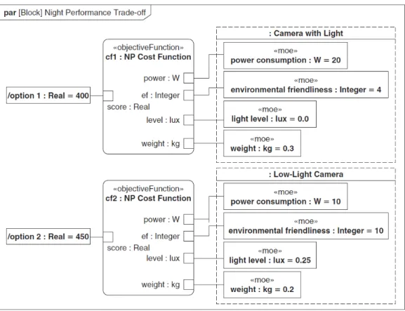
Laying out a Trade Study for the Two Camera Variants (From Friedenthal, Moore and Steiner 2012c, 201) ...43 Figure 22. Trade-off Results Between the Two Low-Light Camera Variants (From
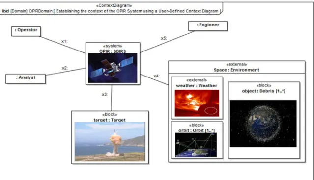
Friedenthal, Moore and Steiner 2012c, 202) ...43 Figure 23. SysML Internal Block Diagram Establishing the Context of the OPIR
System Using a User-Defined Context Diagram ...50 Figure 24. SysML Use Case Diagram Establishing the Top Level Use Cases for the
SBIRS System Which Satisfies the OPIR Mission Area ...51 Figure 25. SysML Use Case Diagram Establishing the Operational Use Cases Which
Further Refine the “Fly the Spacecraft” Use Case...52 Figure 26. SysML Sequence Diagram Establishing the “Black Box” Top-Level Use
Cases and Their Interdependencies ...53 Figure 27. SysML State Machine Diagram Associated with the “Fly the Spacecraft”
Use Case...54 Figure 28. SysML Sequence Diagram Capturing the “Black Box” Interaction for the
“Initialize Spacecraft” Use Case ...55 Figure 29. SysML Sequence Diagram Capturing the “White Box” Interaction for the
“Initialize Spacecraft” Use Case ...56 Figure 30. SysML Requirements Diagram Establishing the OPIR Requirements
Hierarchy...57 Figure 31. SysML Requirements Diagram Establishing the Derived Requirements
and Rationale From the Lowest Tier of the Requirements Hierarchy ...58 Figure 32. SysML Requirements Diagram Capturing the Relationships for the
“Maneuver Capability” Requirement ...59 Figure 33. SysML Activity Diagram Highlighting the Behavior for the “Accelerate”
Function ...60 Figure 34. SysML Block Definition Diagram Decomposing the Activities Associated
with the “Accelerate” Function ...61 Figure 35. SysML Activity Diagram Providing a Detailed Behavior Model for the
“Provide Power” Activity/Function ...62 Figure 36. SysML Block Definition Diagram Defining the OPIR Domain ...63 Figure 37. SysML Block Definition Diagram Defining the Structure of the SBIRS
System ...64 Figure 38. SysML Internal Block Diagram Capturing the Internal Structure of the
SBIRS System ...65 Figure 39. SysML Block Definition Diagram Defining the Structure of the Power
Subsystem ...65 Figure 40. SysML Internal Block Diagram Defining the Internal Structure of the
Figure 42. SysML Internal Block Diagram Detailing the Flow Allocation to the Power Subsystem ...69 Figure 43. SysML Block Definition Diagram Detailing the Definition of “Fuel Flow” ..70 Figure 44. SysML Internal Block Diagram Detailing the Internal Structure of the Fuel
Delivery Subsystem ...71 Figure 45. SysML Parametric Diagram Defining the Fuel Flow Constraints ...72 Figure 46. SysML Block Definition Diagram Defining the Analysis for the SBIRS
Engineering Development ...72 Figure 47. SysML Package Diagram Establishing the Performance View and
Viewpoint of the OPIR Model ...74 Figure 48. SysML Parametric Diagram Defining the Measures of Effectiveness and
Objective Function for Engineering Analysis...75 Figure 49. SysML Parametric Diagram Establishing the Mathematical Relationships
for Analysis ...76 Figure 50. SysML Parametric Diagram Detailing the “Orbital Mechanics”
Mathematical Model ...77 Figure 51. SysML Timing Diagram Showing Sample Results from a SysML
Parametric Analysis. This Example Summarizes Results from the Maximum Acceleration Analysis ...78 Figure 52. SysML and AP233 Data Overlaps (From “SysML and Ap233 Mapping
LIST OF TABLES
Table 1. Department of Defense—Systems Engineering Processes (From Defense Acquisition University 2013i, Chapter 4) ...7 Table 2. Comparison of Model Driven and Document Driven Approaches to
System Design (From Baker, Clemente, Cohen, Permenter, Purves, and Salmon 2013) ...14 Table 3. Structured Analysis and Design Models, Diagrams, and Techniques (From
Long, 2010, 7) ...32 Table 4. Components of the SDL Mapped to MBSE Examples (From Long and
Zane 2011a, 37) ...34 Table 5. Department of Defense—Systems Engineering Processes (From Defense
Acquisition University 2013i)...83 Table 6. Summary of Key Air Force, DoD, and Federal Information Technology
LIST OF ACRONYMS AND ABBREVIATIONS
Alt Alternative
AoA Analysis of Alternatives
AP233 Application Protocol 233
CBAs Capability Based Assessments
CCaR Comprehensive Cost and Requirement System
CDD Capabilities Development Document
CONOPS Concept of Operations
CPD Capabilities Production Document
DoD Department of Defense
DoDAF Department of Defense Architecture Framework
DSP Defense Support Program
FFRDC Federally Funded Research and Development Center
GEO Geosynchronous Orbit
HEO Highly Elliptical Orbit
I/O Input/Output
ICD Initial Capabilities Document
IDEF0 Integrated DEFinition zero
INCOSE International Council on Systems Engineering ISO International Organization for Standardization
LAAFB Los Angeles Air Force Base
MASA Mission Area System Architecture
MBSE Model Based Systems Engineering
MDA Model Driven Architecture
MOE Measure of Effectiveness
OMB Office of Management and Budget
OMG Object Management Group
OPIR Overhead Persistent InfraRed
OV-1 Operational View—1
POR Program of Record
PSMs Platform Specific Models
RFP Request for Proposal
SADT Structured Analysis and Design Technique
SBIRS Space Based InfraRed System
SDS System Design Specification
SE Systems Engineering
SEC Systems Engineering Capability
SEC-ARCH Systems Engineering Capability—Architecture SEC-ARCH Systems Engineering Capability—Architecture SEC-Total Systems Engineering Capability—Total
SEC-TRD Systems Engineering Capability—Trade Studies
SEH Systems Engineering Handbook
SEP Systems Engineering Plan
SMART System Metric and Reporting Tool
SMC Space and Missiles Systems Center
SoS Systems-of-Systems
SysML Systems Modeling Language
TEMP Test and Evaluation Master Plan
UML Unified Modeling Language
USG United States Government
WBS Work Breakdown Structure
EXECUTIVE SUMMARY
The objective of this thesis is to explore the potential benefits of using a model based systems engineering (MBSE) approach, facilitated by a structured architecture modeling language such as the Systems Modeling Language (SysML), to develop and employ mission area architectures for Department of Defense (DoD) space systems. Recently, the need to capture and develop comprehensive architectures for space mission areas within the DoD has drastically increased. It is proposed that in order to respond to this challenge, it is recommended that the DoD depart from its exclusive use of document-driven processes for architecture and acquisition management and adopt a rigorous technique such as MBSE.
MBSE is a formalized approach to modeling and architecting a system across the full system lifecycle. MBSE can be employed to the standards set by the DoD Architecture Framework (DoDAF), which provides the baseline structure and common data meta-model specifications to develop mission area architectures for the DoD, including space systems. Data exchange specifications, such as the ISO 10303 Application Protocol—233 (AP233) standard, can be implemented across a DoD organization to standardize the exchange of architecture and system data between otherwise stove-piped organizational components, enabling synergistic benefits to data analysis across the enterprise. This thesis explores structured techniques, applications, and languages that can be used to enable and aid in the development and assessment of detailed space system architecture, capturing the detailed interactions and interdependencies within and throughout a system and enabling rigorous mathematical analysis to support key programmatic decisions and needs, including the Structured Analysis and Design Technique and the SysML.
In order to realize the maximum benefits of MBSE including, enhanced communications, reduced development risk, improved quality, increased productivity, and enhanced knowledge transfer, a structured architecture development technique such as the Structured Analysis and Design Technique (SADT) or SysML must be
area architectures. A detailed example of the application of SysML, in conjunction with MBSE principles, is provided for the Overhead Persistent Infrared (OPIR) mission area, and specifically modeled for the Space Based Infrared Surveillance System (SBIRS). This SysML model, once complete and specified with mathematical relationships, can be used to support rigorous engineering analysis. Powerful cost-effectiveness comparisons can then be generated as part of an analysis of alternatives or trade study to inform decision makers by answering the question: How well does any particular architecture satisfy the mission requirements? Ultimately, the overall quality of a system acquisition effort, or project, can be greatly improved through the application of MBSE architecture, modeling and simulation, and trade study activities—all enabled by the development of architecture using SysML.
Adopting MBSE and SysML for the design of DoD space systems will require a fundamental paradigm shift in how the DoD does business, transitioning from what is now a purely document-driven approach. Many potential barriers and limitations exist that may limit or impede the introduction of MBSE practices and the application of SysML. Therefore, a three phase approach is recommended in this thesis. The first incremental phase is to identify, list, and manage the configuration of all critical program models, processes, and tools used throughout the Space and Missile Systems Center (SMC). The second recommended phase is to mandate a data exchange specification, such as the AP233 standard, across the DoD space acquisition community to realize some enterprise benefits and aid in the development of requirements for a more integrated and structured approach such as SysML. Simply implementing a data exchange specification would not fundamentally improve how information is managed at the component level, however. Therefore, the third recommended phase is to further standardize the implementation of MBSE practices by enforcing common processes, standards, models, tools, and techniques across the community. As discussed within this paper, the SysML modeling language is uniquely suited to meet this demand. It is clear that such a paradigm shift is required if the DoD and SMC are to meet their requirements for greater
ACKNOWLEDGMENTS
I would like to thank my advisors, Mark Rhoades, Kristin Giammarco, and Mary Vizzini for all of their valuable feedback and support of my research and writing.
Of course, none of this would have been possible if not for the incredible support of my loving wife, Laura, and the patience and never-ending inspiration provided by my daughter, Chloe, and son, Rowan. And to my loving parents, Bruce and Rebecca, for instilling in me the motivation to excel and never give up. For it is my family that provides the stimulus that motivates everything I do.
I.
INTRODUCTION
A. PROBLEM STATEMENT AND OBJECTIVE
The Space and Missile Systems Center (SMC), Los Angeles Air Force Base (LAAFB), California, is the Department of Defense’s (DoD) product center for the Acquisition of all DoD space systems. SMC is organized into program offices responsible for the program management and acquisition of specific space systems, constellations, or portfolios of space systems, along with staff organizations that provide oversight and guidance for all SMC program offices. Given the wide variety of space systems being acquired by SMC and the fact that space systems are among the most complex systems in existence, a great number of elaborate systems engineering and program management tools and processes must be used by every organizational level of SMC and its partners, including the prime and sub-contractors working with the program office to design and build the systems.
Recently, the need to capture and develop comprehensive enterprise architectures for space related mission areas within the DoD has drastically increased. This need is driven by several factors, including the ever increasing complexity of space-based systems-of-systems (SoS) that demand seamless coordination and operation across many organizations and technical interfaces and an austere budget environment demanding that space systems realize maximum efficiencies in the areas of cost, schedule, and performance. A common method is needed to aid in developing and capturing enterprise mission area architectures for use across the DoD space SoS enterprise and applying these common architecture development techniques to all systems designed to operate within the DoD space mission areas.
Typically, a great deal of effort is put forward within each DoD space mission area to plan and develop new systems. The enterprise architectures describing these systems are oftentimes overlooked or over-simplified, only to be later developed in detail by future system acquisition efforts or out of necessity by the defense contractor(s) who is (are) selected to develop and operate the system(s). For instance, although overhead
infrared space systems have been in operations for over 40 years, enterprise architecture descriptions and characterizations for the Overhead Persistent Infrared (OPIR) mission area are just now being developed and shared across the mission area’s stakeholders. Prior to recent efforts to capture enterprise mission area architectures, defense contractors selected to develop and operate the legacy OPIR systems would individually develop, build, operate, and maintain system level architectures for their system(s). This system-specific architecture process has been all too common across the DoD space system enterprise for all mission areas, not just OPIR. As a result, the individual system architectures within a particular space related mission area are tied to specific systems within the mission area, while an enterprise architecture capturing the aggregate of all such systems and their related interfaces and inter-dependencies does not exist. Furthermore, these individual system architectures are oftentimes developed and maintained using different (sometimes unique or highly customized) applications, processes, methods, and techniques.
As a result of this disconnect between system level and enterprise space mission area architectures, it is difficult for a program office to capture the true enterprise mission area architecture containing all related systems, therefore making the program office’s job—that of planning and developing new future systems to fit within an existing enterprise mission area architecture—quite challenging. In the case of the OPIR mission area, legacy systems such as the Defense Space Program (DSP) and other Intelligence Community sensors each have unique system level architectures which were developed by different contractors, executed using unique processes, methods, and techniques, and built with unique hardware and software sub-systems. While these individual system level architectures are well understood by the contractors who built the systems, the overall enterprise architecture containing these systems among others within the OPIR mission area is not well understood. Consequently, when the space acquisition community is studying and investigating follow-on systems to replace these legacy platforms, such as the Space Based Infrared Surveillance (SBIRS) system, this lack of
capabilities and functions need to be performed by the new system of systems (SoS), how legacy systems might be impacted by new systems, where commonality might exist across the systems within the enterprise, and so on. Having a comprehensive understanding of architecture considerations such as these is not only critically important for conducting trade studies, developing systems, or managing any other systems engineering activity, but is essential to understanding the impact on the overall cost, schedule, and performance levels of the SoS enterprise (e.g., reducing unnecessary redundancy and waste; reducing system level re-work; ensuring the enterprise of systems as a whole most effectively and efficiently satisfies requirements).
Model based systems engineering is a discipline that prescribes configuration controlled graphical models and views for use in managing the systems engineering activities of a system. MBSE has been widely studied and applied as a powerful systems engineering method, particularly as a tool to capture, develop, communicate, and manage system architectures. A specific MBSE architecture format or modeling language, however, has not yet emerged for DoD space applications. A relatively new systems engineering modeling language now exists—the systems modeling language (SysML). SysML has grown out of two different but related disciplines—MBSE and Software Engineering. SysML has been adopted by many organizations because it is a highly adaptable and executable modeling language, particularly concerning systems with highly complex software sub-systems. While communicating and relating system architectures across systems, organizations, and disciplines is one of the most significant challenges facing the development of a true enterprise architecture, the fact that SysML has shown itself to be flexible, adaptable, and used by many organizations makes it a strong candidate as the common standard language for developing MBSE architectures. As SysML shows high potential and promise of becoming a new standard method for conducting model based systems engineering, it is logical that it could have great potential as a common, standard, language tool for developing true mission area architectures for DoD space related mission areas, such as the OPIR mission area.
The purpose of this research is to assess model based systems engineering techniques in conjunction with methods and applications such as the enterprising system
modeling language and recommend specific applications to aid in the development of space based mission area architectures for the Department of Defense.
B. RESEARCH QUESTIONS
1. Primary research question: What methods, techniques, and processes can be employed to aid in the development of mission area architectures for Department of Defense (DoD) space systems?
2. Subsidiary research questions:
a. In what ways or in what instances can model based systems engineering (MBSE) be used in the development of space based mission area architectures for the DoD?
b. How can the system modeling language (SysML), based on the common Software Engineering Unified Modeling Language (UML), be applied to aid in developing mission area architectures for DoD space systems?
C. BENEFITS OF STUDY
The study being conducted during this thesis will benefit the DoD by prescribing a standardized process and framework from which model based systems engineering can be executed and enterprise architectures developed for any given mission area. Through demonstration of this technique for the Overhead Persistent Infrared (OPIR) mission area architecture, the real-world applicability and feasibility of these concepts will be explored. Organizations that could benefit from the study include the U.S. Government (USG) and any organization contracting with the USG, particularly the DoD, each military service, and the larger space acquisition community.
II.
DOD ACQUISITION AND SYSTEMS ENGINEERING
PROCESSES
The DoD outlines the overarching acquisition policy, procedures, and guidance to be adhered to by all military services, including the U.S. Air Force, in DoD Instruction 5000.02 Operation of the Defense Acquisition System (Defense Acquisition University 2013h). The System Acquisition Framework prescribed by this DoD instruction is shown in Figure 1.
Figure 1. Department of Defense System Acquisition Framework (From Department of Defense 2008)
As shown in Figure 1, the System Acquisition Framework outlines specific phases of a major DoD acquisition program into the categories of pre-systems acquisition, systems acquisition, and sustainment. Milestones (as indicated by letters in triangles in Figure 1) separate the phases of the acquisition process, each requiring specific entrance and exit criteria for passage into the next phase. DoD Instruction 5000.02 details a wealth of specific documentation that must accompany each of the milestones, reviews, and phases outlined in the system acquisition framework shown in Figure 1. Examples of such documentation include, but are not limited to, the initial capabilities document (ICD), capabilities development document (CDD), capabilities production document (CPD), systems engineering plan (SEP), test and evaluation master plan (TEMP),
concept of operations (CONOPS), system design specification (SDS), and an analysis of alternatives (AoA). (Defense Acquisition University 2013a) This overarching acquisition process for the DoD, as it exists today, is a very document-focused and document-driven process in which phased documentation artifacts, including those summarized above, are generated at a specific instance in time and, in general, are used as static tools to manage the acquisition of a system.
DoD Instruction 5000.02 further defines the core disciplines necessary to implement the System Acquisition Framework (Department of Defense [DoD] 2008). Once such discipline is systems engineering, which is defined within DoD Instruction 5000.02 as “the integrating technical processes to define and balance system performance, cost, schedule, and risk within a family-of-systems and systems-of-systems context” (Defense Acquisition University 2013g, Enclosure 12). It further defines systems engineering in reference to the System Acquisition Framework by prescribing that “Systems engineering shall be embedded in program planning and be designed to support the entire acquisition life cycle” (Defense Acquisition University 2013g, Enclosure 12). While DoD Instruction 5000.02 provides one definition of systems engineering, many other definitions of systems engineering exist. The International Council on Systems Engineering (INCOSE) defines systems engineering as:
an interdisciplinary approach and means to enable the realization of successful systems. It focuses on defining customer needs and required functionality early in the development cycle, documenting requirements, then proceeding with design synthesis and system validation while considering the complete problem. (INCOSE 2004)
In order to conduct the discipline of systems engineering, structured systems engineering processes must be adhered to.
One such systems engineering process has been established by the Defense Acquisition Guidebook, which corresponds to DoD Instruction 5000.02. The structure of this systems engineering process is maintained within the Defense Acquisition Guidebook, which defines the systems engineering process as “a collection of technical
outline the distinct technical management processes and technical processes summarized in Table 1 (Defense Acquisition University 2013i).
Technical Management Processes Technical Processes
Technical Planning Stakeholder Requirements Definition
Decision Analysis Requirements Analysis
Technical Assessment Architecture Design
Requirements Management Implementation
Risk Management Integration
Configuration Management Verification
Technical Data Management Validation
Interface Management Transition
Table 1. Department of Defense—Systems Engineering Processes (From Defense Acquisition University 2013i, Chapter 4)
The SE processes listed in Table 1 are conducted by the program manager and the systems engineer in an iterative, recursive, and parallel fashion throughout the acquisition life cycle. The relative degree of emphasis the program manager and systems engineer should expect to apply to each of the management and technical systems engineering processes listed in Table 1 during each phase of the System Acquisition Framework shown in Figure 1 is represented in Figure 2 (Defense Acquisition University 2013e).
Figure 2. Notional Emphasis of Systems Engineering Processes Throughout the Defense Acquisition System Life Cycle (From Defense Acquisition
University 2013e, Chapter 4)
These systems engineering technical management processes are implemented across each phase of the system acquisition framework following the “V” model structure, as shown in Figures 3 and 4.
Figure 3. Department of Defense—Systems Engineering Technical Management Processes (From Defense Acquisition University 2013f)
Figure 4. Department of Defense—Defense Acquisition Management System Technical “V” Activities (From Defense Acquisition University 2013f, Defense
Acquisition Management System)
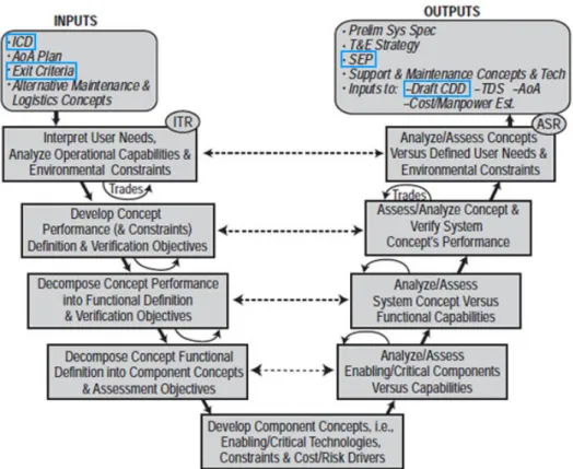
Each instantiation of this “V” model includes specific inputs, outputs, documentation requirements and activities for each technical management and technical process. An example of the systems engineering “V” model applied to the material solution analysis phase is shown in Figure 5. The required input and output
during the material solution analysis phase of the system acquisition framework are highlighted by blue boxes.
Figure 5. “V” Model Highlighting Phasing and Relationships Between Systems Engineering Activities Conducted Throughout the Materiel Solution Analysis
Phase of the Defense Acquisition Framework (From Defense Acquisition University 2013j)
Of particular note from this systems engineering process prescribed by DoD Instruction 5000.02 are the requirements for documentation release at specific points in the acquisition process. Many of these documents, such as the initial capabilities document (ICD), systems engineering plan (SEP), and the capabilities development document (CDD) are further restricted by templates or format requirements. While the tasks, activities, and concepts of the systems engineering process described by DoD Instruction 5000.02 are flexible guidelines to meet the objectives of systems engineering, the
process itself. Model based systems engineering, at its core, aims to shift from a document-focused systems engineering process to a repeatable and executable process that allows implementation of the tasks, activities, and concepts of the systems engineering process introduced above and defined within DoD Instruction 5000.02 while improving implementation and design flexibility through the application of dynamic products and models tailored specifically to the unique systems engineering application.
III.
MODEL BASED SYSTEMS ENGINEERING AND THE
SYSTEMS MODELING LANGUAGE FOR SYSTEMS
ENGINEERING AND ARCHITECTURE DEVELOPMENT
Breaking from the document-based systems engineering approach, model based systems engineering (MBSE) provides the systems engineer, architect, and designer with rigorous capabilities for conducting requirements analysis, system and sub-system design and analysis, modeling and simulation, and system verification and validation information. As is stated in A Primer for Model Based Systems Engineering, “in traditional systems engineering approaches, requirements reviews most often occur without adequate allocation to the physical or logical representations. Because the model-based approach addresses the allocation systematically, it leads to a better-grounded method for validating the system design” (Long and Scott 2011d, 98).
Table 2 summarizes some of the different level of features available from model-driven versus document-centered system design processes, from which we can see further benefits of a model-driven process such as MBSE over rigid document-based process such as those over-prescribed by the DoD System Acquisition Framework and DoD Instruction 5000.02.
Table 2. Comparison of Model Driven and Document Driven Approaches to System Design (From Baker, Clemente, Cohen, Permenter, Purves, and Salmon 2013)
The document-centered approach to designing and developing large complex systems brings about significant challenges in configuration management, flexibility, documentation synchronization, and enterprise collaboration. For such reasons, in INCOSE Systems Engineering Vision 2020, it is predicted that all systems engineering will evolve, as other engineering disciplines including mechanical, electrical, and software already have, from a document-centered to a model-driven process:
In particular, Model Based Systems Engineering (MBSE) is expected to replace the document-centric approach that has been practiced by systems engineering in the past and to influence the future practice of systems engineering by being fully integrated into the definition of systems engineering processes. (INCOSE 2007)
A. SYSTEM MODELS
According to Long as Scott, “Models are common to human experience as aids for understanding the way the world works.” (Long and Scott 2011e) In a general sense, we all use models in our daily lives to represent oftentimes more complex systems or concepts. Specific to systems engineering:
models connect the idea behind a design solution with its implementation as a real system. These models attempt to represent the entities of the engineering problem (opportunities) and their relationships to each other and connect them to the proposed solution or existing mechanism that addresses the problem. The model used in this way is the centerpiece of MBSE. (Long and Scott 2011e)
The concept of a model can be further defined by decomposition into fundamental elements (language, structure, argumentation, and presentation) and characteristics (order, power to demonstrate and persuade, integrity and consistency, and insight). Each of these four model elements and four model characteristics, as defined by David Long and Zane Scott in A Primer for Model-Based Systems Engineering is further defined below: (Long and Scott 2011c, 32–33)
Four Elements of a Model:
Language—The basis for the modeling approach itself. The system
definition language must be clear and unambiguous in order to depict the model accurately and understandably.
Structure—Allows the model to capture system behavior by clearly
describing the relationships of the system’s entities to each other.
Argumentation—The purpose of the model is to represent the system in such a way that the design team can demonstrate that the system accomplishes the purposes for which it is designed. Therefore the model must be capable of making the critical “argument” that the system fulfills the stakeholders’ requirements.
Presentation—Not only must the system be capable of making that
argument, but it must include some mechanism of showing or “presenting” the argument in a way that can be seen and understood. (Long and Scott, 2011c)
Long and Scott also elaborate on the four characteristics of a system model:
Four Characteristics of a System Model:
Order—Allows the design team to attach the problem in a coherent
and consistent manner leading to a viable solution. The model provides the order that becomes the framework for this effort.
Power to Demonstrate and Persuade—By representing the relevant
behaviors in proper relationship to the system entities, the model allows the designer to see and demonstrate the necessary system behavior. This becomes persuasive in making the case that a given solution answers the needs that drive the design of the system.
Integrity and Consistency—Ambiguity and inconsistency in the
system design lead to design flaws which, in turn, harm the credibility of the argument that the system design meets the needs it was designed to meet. The model must, therefore, provide the integrity and consistency that lead to a sound solution.
Insight—The model provides insight into the system problem facing the design team as well as the potential design solutions. By the model’s representation of the system behaviors and relationships, the design team is able to gain insight into the comparative advantages of different approaches to solving the design problem at hand. (Long and Scott 2011b, 32–33)
As Long and Scott highlight through their definitions of model elements and characteristics, models are customizable and adaptable tools which can be used by a systems engineer to design and gain unique insight into a system. There are many different modeling techniques and languages in use today that were developed to fit these definitions. For instance, examples of modeling languages for systems engineering applications include the system definition language (SDL), which is used for the structured analysis approach (realized by a modeling tool such as Vitech CORE) and the systems modeling language (SysML), which is elaborated on later as a focus of this report.
B. MODEL BASED SYSTEMS ENGINEERING
Model based systems engineering describes a set of interrelated models and views used to characterize and analyze a system design throughout its lifecycle. In Systems Engineering Vision 2020, the International Council on Systems Engineering (INCOSE)
support system requirements, design, analysis, verification and validation, beginning in the conceptual design phase and continuing throughout development and later life cycle phases” (INCOSE 2007, 15).
The principles of model based systems engineering provide the framework for organizations to select a set of interrelated models to help characterize and analyze a system and document the design, acquisition and sustainment process. Using MBSE, organizations can select a set of models and views catered to meet their specific needs and, through this application, realize significant improvements to their processes and ultimately the products they produce. The selection and use of common models throughout and across organizations will help to improve communications between stakeholders, managers, and developers by providing a common ground for discussion. By standardizing these models, managers and developers can not only communicate more effectively within their program but also between multiple programs across their organization. This open communication between programs can help to facilitate the open exchange of ideas and lessons learned from one program to another, combating the “stove-piped” structure often seen between programs within a large organization or product center.
In their book, A Practical Guide to SysML—The Systems Modeling Language (2012a), Friedenthal, Moore, and Steiner advocate the benefits of MBSE by highlighting that it:
…provides an opportunity to address many of the limitations of the document-based approach by providing a more rigorous means for capturing and integrating system requirements, design, analysis, and verification information, and facilitating the maintenance, assessment, and communication of this information across the system’s life cycle. (20)
Friedenthal, Moore, and Steiner (2012a) further list the potential benefits of MBSE, which include:
Enhanced communications
• Shared understanding of the system across the development team and other stakeholders
Reduced development risk
• Ongoing requirements validation and design verification
• More accurate cost estimates to develop the system Improved quality
• More complete, unambiguous, and verifiable requirements
• More rigorous traceability between requirements, design, analysis, and testing
• Enhanced design integrity Increased productivity
• Faster impact analysis of requirements and design changes
• More effective exploration of trade-space
• Reuse of existing models to support design evolution
• Reduced errors and time during integration and testing
• Automated document generation Leveraging the models across life cycle
• Support operator training on the use of the system
• Support diagnostics and maintenance of the system Enhanced knowledge transfer
• Capture of existing and legacy designs
• Efficient access and modification of the information. (Friedenthal, Moore and Steiner 2012a, 20)
In addition to facilitating better communication and understanding throughout an organization, MBSE also improves the quality of the information presented by these models and facilitates reuse of that information. Model based systems engineering describes the use of a common database to integrate and relate the information presented by multiple models and views. There are significant benefits to employing a common integrated database to a modeling approach. At the 22nd Annual INCOSE International Symposium, representatives of the Boeing Company summarized these “benefits of MBSE in an integrated environment” (Gau Pagnanelli, Sheeley and Carson 2012), listed below:
• Single data environment ensures completeness & consistency of design data
• Rich database permits multi-user input and immediate
synchronization, improving efficiency and productivity
• Use of a single data environment results in data availability throughout program life-cycles
• Robust query engine allows rapid assessment of the integrated database, finding anomalies early, preventing rework. (Gau Pagnanelli, Sheeley and Carson 2012)
By using an integrated database environment to capture the model data, valuable real-time relationships between the information, models, and the decisions they support can be realized, significantly improving the value of each model and the maintenance of the supporting data. For instance, requirements can be presented in a hierarchy showing the parent-child relationships among and between them, and source and issue linkages can be maintained as the requirements evolve. Using the common database concept, this requirements model can then be integrated with other models, such as the design architecture for a system and the risk analysis tracking tools for the associated program. The allocation of these requirements to specific architecture components and/or functions can then be shown along with the traceability of these requirements to the mission level requirements (Baker and Christian 2013). More and more complex relationships can be defined between the many models used to characterize a system and relate design issues to management initiatives associated with risk, configuration control and interface management. The common database helps with the maintenance of these interrelated models and views by allowing managers and engineers to make a single change to the database and observe the change uniformly across all applicable models and views.
C. SYSTEM ARCHITECTURE DESIGN AND DEVELOPMENT
A critical part of the systems engineering process, system architecture design is the primary tool used by systems engineers and system architects for much of the up-front system design and definition work throughout the pre-systems acquisition phase of the system acquisition framework. As is the case with the systems engineering discipline, there are many diverse definitions of system architecture. In the INCOSE Systems Engineering Handbook v. 3.2.2, system architecture is defined as “the arrangement of elements and subsystems and their functional allocation to meet system requirements” (INCOSE 2011, 96). The INCOSE Systems Engineering Handbook (SEH) further expands this definition by stating that “system… architectures depict the summation of a system’s entities and capabilities at levels of abstraction that support all
stages of deployment, operations, and support” (INCOSE 2011, 98). The DoD Architecture Framework (DoDAF) defines system architecture as “the structure of components, their relationships, and the principles and guidelines governing their design and evolution over time” (DoD 2009, 249). In other words, system architecture is all-encompassing of a system’s design and description and is an evolutionary process—two tenets that correlate strongly to the principles of MBSE which outlines evolving products used to design and capture the entirety of a system design.
As previously discussed, system architecture design and development is an iterative and recursive process. DoD Instruction 5000.02 identifies the key activities of the architecture design process as:
• Analysis and synthesis of the physical architecture and the appropriate allocation
• Analysis of the constraint requirements
• Identify and define physical interfaces and system elements
• Identify and define critical attributes of the physical system elements, including design budgets (e.g., weight, reliability) and open system principles. (Defense Acquisition Guidebook 2013b, 4.3.12)
D. WHY FOCUS ON SYSTEM ARCHITECTURE AND TRADE STUDIES?
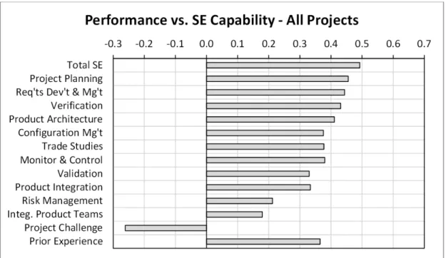
Joseph Elm and Dennis Goldenson of Carnegie Mellon conducted a study assessing the business case for systems engineering. (Elm and Goldenson 2012) Figures 6–8 summarize the results of their study in representing the correlation between the quality of the systems engineering processes and techniques that were applied during development and their impact to the overall project performance. The study defines the term systems engineering capability (SEC) to measure the rigor of SE activities applied to a project. In addition to assessing the total SE activities (SEC-Total) applied to a project, the study decomposed SEC-Total into 11 measures of SE capability, including product architecture (SEC-ARCH) and trade studies (SEC-TRD) (Elm and Goldenson 2012, 12)
variables. Gamma values can range from “-1” which indicates a very strong opposing relationship to “+1” which indicates a very strong supporting relationship. A Gamma value of zero indicates that there is no relationship between the two variables in question. As can be seen in Figure 6, Elm and Goldenson assessed a Gamma value of +0.41 for Product Architecture, indicating that there is a significant positive correlation between Product Architecture efforts and the overall performance of a project. Furthermore, the figure shows there to be nearly as strong a correlation between the quality of trade studies conducted and the project performance, a supporting fact that will later provide additional justification to SySML techniques for MBSE and system architecture design and development.
Figure 6. Strength of Correlation Between Various Systems Engineering Capabilities/Drivers and Overall Project Performance (From Elm and
Goldenson 2012, Executive Summary)
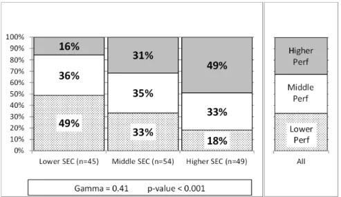
Elm and Goldenson’s study results further elaborate on this correlation between systems engineering activities such as architecture and trade studies and overall project performance by showing how project performance increases as the systems engineering
highlights this strong supporting relationship between architecture development and the project performance. As can be observed in Figure 7, the percentage of projects delivering higher overall performance (y-axis) increases from 16 percent to 31 percent to 49 percent as the level of product architecture efforts, or SEC-ARCH (x-axis), increases from low to middle to high, respectively.
Figure 7. Mosaic Chart Comparing Various Level of SEC-ARCH to Overall Project Performance (From Elm and Goldenson 2012, 35)
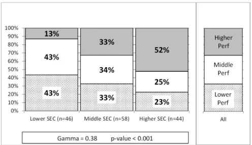
Figure 8 shows a similarly strong supporting relationship between trade studies and project performance, identifying an increase in overall project performance from 13 percent to 33 percent to 52 percent as the SEC-TRD increases from low to middle to high.
Figure 8. Mosaic Chart Comparing Various Level of SEC-TRD to Overall Project Performance (From Elm and Goldenson 2012, 38)
E. MODELING AND SIMULATION
Model based systems engineering is a powerful tool for system engineers, designers and architects because it provides strong structural support to simulation. Like models, simulations are systems engineering tools used by multiple functional disciplines throughout all lifecycles of a system. DoD Instruction 5000.02 defines modeling as “an essential [tool] to aid the understanding of complex systems and system interdependencies, and to communicate among team members and stakeholders.” It relates simulation to modeling by stating, “simulation provides a means to explore concepts, system characteristics, and alternatives; open up the trade space; facilitate informed decisions and assess overall system performance” (Defense Acquisition University 2013c, 4.3.19.1). Elaboration on this definition is provided in DoD Instruction 5000.02 in the summary of the benefits of modeling and simulation listed below:
Provides insight into program cost, schedule, performance, and supportability risk
Promotes understanding of capabilities and the requirements set Provides data to inform program and technical decisions
system being developed, through precise engineering artifacts and traceability of designs to requirements
Enables better analysis and understanding of system designs (including system elements and enabling system elements), therefore providing a greater understanding of the reasons for defects and failures at all levels
Promotes greater efficiencies in design and manufacturing by reducing the time and cost of iterative build/test/fix cycles
Provides timely understanding of program impacts of proposed changes. (Defense Acquisition University 2013c, 4.3.19.1)
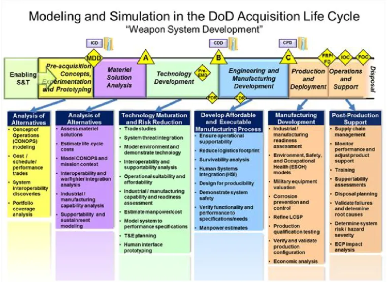
The activities and benefits of modeling and simulation to each phase of the System Acquisition Framework are summarized in Figures 9 and 10.
Figure 9. Benefits of Using Modeling and Simulation Throughout the Acquisition Life Cycle (From Defense Acquisition University 2013c, 4.3.19.1)
As previously discussed, a simulation activity with particularly strong correlation to strong project performance is the analysis of alternatives, otherwise known as trade studies. While architecture design and development and trade study activities are both critical to the success of a project, they also happen to be highly correlated and interdependent activities throughout the pre-system acquisition phase of the acquisition lifecycle. It is the combination of the benefits realized as a result of rigorous architecture design and development and trade study activities that drive the MBSE approach, which is particularly well suited to strongly support both of these activities. Furthermore, as it will be shown, it is the opinion of the author of this report that the systems modeling language (SysML) is a particularly well suited approach to MBSE, which in turn optimizes both architecture design and development and trade study activities to realize the maximum potential of the MBSE approach to systems engineering.
F. ANALYSIS OF ALTERNATIVES
Section 3.3 of the Defense Acquisition Guidebook defines an analysis of alternatives (AoA) as “an analytical comparison of the operational effectiveness, suitability, and life-cycle cost (or total ownership cost, if applicable) of alternatives that satisfy established capability needs” (Defense Acquisition University 2013a, 3.3). In more general systems engineering terms, the AoA activity outlined by DoD Instruction 5000.02 is a trade study.
As part of an AoA or trade study, a team of engineers and analysts must conduct a comparison of competing system concepts and solutions which satisfy a set of requirements, and this must be done by assessing a broad range of system measures. These measures are analyzed across the system architecture hierarchy for each system, compared against component level or activity level measures of effectiveness (MOEs), and ultimately compiled into a top-level effectiveness MOE for each system. MBSE techniques and established system architectures are critical components in support of determining this effectiveness MOE for each system, as will be shown in the case study
focused on the computation of the specific measures of effectiveness established for the purpose of the particular study” (Defense Acquisition University 2013a, 3.3).
In addition to computing the overall effectiveness of each system concept, an AoA or trade study, must estimate the total life cycle cost for each system. Once the overall effectiveness or performance and estimated life cycle cost of each system is derived, cost-effectiveness comparisons can be developed and presented as powerful tools to decision makers to ultimately select one system concept to implement from among all concepts considered within a trade study. An example of a cost-effectiveness comparison is shown in Figure 11.
Figure 11. Cost-Effectiveness Comparison—Sample Scatter Plot of Effectiveness vs. Cost (From Defense Acquisition University 2013a, Chapter 3.3)
The cost-effectiveness comparison plot in Figure 11 is an example of how the overall system effectiveness, plotted on the y-axis, can be compared to the life cycle cost,
plotted on the x-axis, for each system alternative considered within a trade study. As shown in Figure 11, “Alt 4” and “Alt 5” are dominated by “Alt 6,” which is expected to achieve the same level of effectiveness as the other dominated alternatives but at a lower life cycle cost. Taking into additional consideration any technical or schedule risk and other programmatic aspects, a decision maker could use a cost-effectiveness comparison plot like this to inform the selection of the system alternative to continue through the acquisition life cycle.
G. MBSE ARCHITECTURE TOOLS AND TECHNIQUES
There are many tools and techniques that support MBSE and are in use by systems engineering and systems architects around the world. While it is beyond the scope of this thesis to analyze and assess each of these tools and techniques, the most commonly used MBSE affiliated processes are introduced below.
1. Department of Defense Architecture Framework (DoDAF)
A very visible framework is the Department of Defense Architecture Framework, i.e., the DoDAF. As is stated in DoDAF v. 2.0:
The Department of Defense Architecture Framework (DoDAF), Version 2.0 is the overarching, comprehensive framework and conceptual model enabling the development of architectures to facilitate the ability of Department of Defense (DoD) managers at all levels to make key decisions more effectively through organized information sharing across the Department, Joint Capability Areas (JCAs), Mission, Component, and Program boundaries. (Department of Defense, DoDAF v. 2.0 2009, 2)
DoDAF defines a way of representing an enterprise architecture that enables stakeholders to focus on specific interests, while retaining sight of the big picture:
To assist decision-makers, DoDAF provides the means of abstracting essential information from the underlying complexity and presenting it in a way that maintains coherence and consistency. One of the principal objectives is to present this information in a way that is understandable to the many stakeholder communities involved in developing, delivering, and
The DoDAF describes specific viewpoints from which each stakeholder can view the overarching model. Each of these viewpoints is designed to organize information from the architecture model and present it using models (e.g., graphs, tables, figures.) catered to a specific audience who can then use the model insights for system design and for decision making purposes. The viewpoints outlined by DoDAF 2.0 are summarized in the next section and shown in Figure 12.
Figure 12. DoD Architecture Framework v. 2.0—Viewpoint (From Department of Defense 2009, 140)
The DoDAF defines each of these viewpoints as summarized below:
All Viewpoint: describes the overarching aspects of architecture
context that relate to all viewpoints.
Capability Viewpoint: articulates the capability requirements, the delivery timing, and the deployed capability.
Data and Information Viewpoint: articulates the data relationships and alignment structures in the architecture content for the capability and operational requirements, system engineering processes, and
Operational Viewpoint: includes the operational scenarios, activities, and requirements that support capabilities.
Project Viewpoint: describes the relationships between operational and capability requirements and the various projects being implemented. The Project Viewpoint also details dependencies among capability and operational requirements, system engineering processes, systems design, and services design within the Defense Acquisition System process. An example is the V-charts in Chapter 4 of the Defense Acquisition Guide.
Services Viewpoint: the design for solutions articulating the
Performers, Activities, Services, and their Exchanges, providing for or supporting operational and capability functions.
Standards Viewpoint: articulates the applicable operational, business, technical, and industry policies, standards, guidance, constraints, and forecasts that apply to capability and operational requirements, system engineering processes, and systems and services.
Systems Viewpoint: the design for solutions articulating the systems, their composition, interconnectivity, and context providing for or supporting operational and capability functions. (Department of Defense 2009, 140)
DoDAF 2.0 defines specific model viewpoints, some of which are required for major system acquisitions, and provides examples of specific models that meet these viewpoint requirements. Unlike previous releases, however, the latest DoDAF 2.0 focuses on describing the meta-model which underlies its structure and does not dictate a specific model or modeling language that must be used to satisfy any particular view or viewpoint. Because of this, any MBSE tool and technique that includes a wide range of different modeling tools, types, and languages—including structured analysis and SysML—are capable of being compliant with the DoDAF 2.0 requirements.
2. Structured Analysis and Design Technique
As is described in the Handbook of Systems Engineering and Management, “the structured analysis approach has its roots in the structured analysis and design technique (SADT) that originated in the 1950s and encompasses structured design, structured development, the structured analysis approach of DeMarco, and structured systems
functional architecture of a system. These four components and their relative interactions are represented in Figure 13, and include the process model, data model, and rule model, along with an integrated system dictionary to manage the data supporting each model category to ensure consistency. SADT also includes dynamics modeling techniques which integrate across all three of the model categories shown.
Figure 13. Components of the Structured Analysis and Design Technique (From Sage and Rouse 2011, 485)
The most commonly used model diagrams and techniques employed to the process model, data model, rule model, and dynamics model are summarized in Table 3.