Rocket performance
7.1
Thrust
Figure 7.1 shows a sketch of a rocket in a test stand. The rocket produces thrust, T , by expelling propellant mass from a thrust chamber with a nozzle. The test stand applies an opposite force on the rocket holding it at rest. The propellant (fuel+oxidizer) mass flow rate is ˙m and the ambient pressure of the surrounding air isP0.
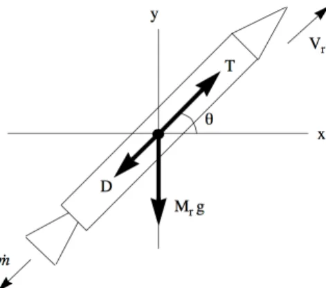
Figure 7.1: Rocket thrust schematic.
Other quantities defined in Figure 7.1 are as follows.
As=outside surf ace of the vehicle exposed to P0
Ac=inside surf ace of the combustion chamber Ae=nozzle exit area
ˆ
n=outward unit normal
Pe=area averaged exit gas pressure
⇢e=area averaged exit gas density
Ue =area averaged x component of velocity at the nozzle exit
(7.1)
The vehicle is at rest and so the total force acting on it is zero. 0 =T + Z As ⇣ P I ⌧⌘·ndAˆ x + Z Ac ⇣ P I ⌧⌘·ndAˆ x + ˙mUxm (7.2) The variable P is the gas pressure acting at any point on the surface of the rocket, ⌧ is the viscous stress tensor, and ˙mUxm is the x-momentum of the propellant injected into the thrust chamber. If the rocket were inactive so that there was no force on the restraint and the outside surface and thrust chamber were all at a pressure P0 then
0 = Z As P0I·ndAˆ x + Z Ac P0I·ndAˆ x . (7.3)
In this situation the control volume contains fluid all at rest and
0 = Z Ac P0I·ˆndA x + Z Ae P0I·ndAˆ x . (7.4)
The last relation can be written as
0 = Z Ac P0I·ndAˆ x +P0Ae. (7.5) Note that a unit normal vector that is consistent between the control volume and the outside surface of the vehicle points inward onAe. Thus equation (7.3) becomes
0 = Z As P0I·ˆndA x P0Ae (7.6)
and the original force balance (7.2) can be written as
0 =T+P0Ae+ Z Ac ⇣ P I ⌧⌘·ndAˆ x + ˙mUxm. (7.7) Built into (7.7) is the assumption that when the engine is operating the external surface pressure and stress distribution is unchanged.
✓Z As ⇣ P I ⌧⌘·ndAˆ x ◆
af ter engine turn on = ✓Z As P0I·ˆndA x ◆
bef ore engine turn on (7.8) In fact, the jet from the rocket mixes with the surrounding air setting the air near the vehicle into motion leading to slight deviations in the pressure acting on the outside of the vehicle. For a rocket of reasonable size and thrust, this is a very small e↵ect.
With the engine on, a balance of momentum over the control volume gives D Dt Z V ⇢U dV¯ = Z V ✓ @⇢U¯ @t ◆ dV = Z V r· ⇣ ⇢U¯U¯ +P I ⌧⌘dV. (7.9) We are treating the case where the flow in the combustion chamber is stationary and the integral on the left hand side of (7.9) is zero. Our goal is to relate the thrust of the engine to flow conditions onAeand with this in mind we convert the right hand side to an integral over the surface of the control volume.
0 = Z V r· ⇣ ⇢U¯U¯+P I ⌧⌘dV = Z Ac ⇣ ⇢U¯U¯ +P I ⌧⌘·ndAˆ + Z Ae ⇣ ⇢U¯U¯ +P I ⌧⌘·ndAˆ (7.10)
Note that the unit normal that appears in the surface integrals in (7.10) is an inward pointing unit normal. On the surface Ac, the velocity is zero by the no-slip condition (except over the injector holes) and on the surface Ae we use area-averaged values of velocity, pressure, and density
Z
Ac
⇣
P I ⌧⌘·ndAˆ x
+ ˙mUxm+⇢eUe2Ae+PeAe= 0 (7.11) where the momentum of the propellant injected into the combustion chamber has been included. Small viscous normal forces on Ae are neglected. Our force balance (7.7) now becomes
0 =T +P0Ae ⇢eUe2Ae+PeAe . (7.12) Finally our rocket thrust formula is
T =⇢eUe2Ae+ (Pe P0)Ae. (7.13) The propellant mass flow is
˙
m=⇢eUeAe (7.14) and the rocket thrust formula is often written
T = ˙mUe+ (Pe P0)Ae. (7.15)
7.2
Momentum balance in center-of-mass coordinates
Let’s look at the question of defining the thrust from a rather di↵erent point of view. Figure 7.2 depicts a rocket referenced to a system of center-of-mass coordinates. In the analysis to follow, gravity is taken to be zero. The e↵ects of gravitational acceleration will be taken into account later.
Fort <0 the rocket, its propellant and the surrounding atmosphere are all at rest. Some-time after ignition the rocket has translated to the right and the exhaust gases form a cloud o↵to the left of the center-of-mass. Because there is no external force on the system the center of mass remains at rest at the origin for all time. Conservation of momentum for the whole system of rocket vehicle, expelled combustion gases as well as the air set into motion by the drag forces on the rocket can be stated as
D Dt Z V(t) ⇢U dV¯ x +Mr(t)Vr(t) ! = 0 (7.16)
where Mr(t) is the time-dependent rocket mass. At any given instant the rocket mass comprises all of the hardware and all of the propellant contained in the tanks, piping, pumps and combustion chamber up to the exit plane of the nozzle. The time-dependent rocket velocity is Vr(t). We shall assume that all of the propellant mass contained in the rocket is moving at this velocity although there is always a small amount moving through the piping and combustion chamber at a slightly di↵erent velocity.
The gas momentum is integrated over a control volume V(t) that completely encloses all of the moving gas outside the vehicle as shown in Figure 7.2. Since there is a continuous flow of propellant mass into the combustion chamber and out of the rocket nozzle the volume required to contain the expelled gas must grow with time. This is depicted in Figure 7.2. The control volume is cylindrical in shape. The left face A1 moves to the left at a speed
sufficient to fully contain all the moving gas as well as any unsteady pressure disturbances generated by the rocket plume. The surface A3 moves outward for the same reason. The
upstream faceA2 moves to the right at velocityVr(t) with the rocket. Finally the surface As is attached to the rocket fuselage and outer nozzle surface. On the solid surface, the fluid velocity is equal to the rocket velocityVr(t) by the no slip condition. The last surface of the control volume is Ae which coincides with the nozzle exit plane and translates to the right at the rocket velocity. The momentum equation integrated overV (t) is
D Dt Z V(t) ⇢U dV¯ x = Z A(t) ⇣ ⇢U¯ U¯ U¯A +P I ⌧ ⌘ ·ndAˆ x . (7.17)
The control volume is sufficiently large so that the fluid velocity onA1 ,A2 and A3 is zero
and the pressure is P0. Therefore over most of the surface of the selected control volume
no additional momentum is being enclosed as the surface moves outward. The pressure forces onA1 and A2 nearly cancel except for a small deviation in pressure near the rocket
nose in subsonic flight. For now we will cancel these forces but they will be included later when we develop an expression for the vehicle drag. The pressure forces on A3 have no
D Dt Z V(t) ⇢U dV¯ x = Z As(t) ⇢U¯ U¯ U¯A +P¯¯I ¯¯⌧ ·ndAˆ x Z Ae(t) ⇢U¯ U¯ U¯A +P¯¯I ¯¯⌧ ·ndAˆ x . (7.18)
Now we can use an argument similar to that used in the previous section to relate the surface integral of the ambient pressure to an integral over the nozzle area. Recall
0 = Z As P0I·ndAˆ x +P0Ae. (7.19) The sign change in (7.19) compared to (7.6) comes from the change in the direction of the outward normal onAecompared to the control volume used in Section 7.1. Subtract (7.19) from (7.18) to get D Dt Z V(t) ⇢U dV¯ x = Z As(t) ⇢U¯ U¯ U¯A + (P P0)¯¯I ¯¯⌧ ·ndAˆ x Z Ae(t) ⇢U¯ U¯ U¯A + (P P0)¯¯I ¯¯⌧ ·ndAˆ x . (7.20)
On the no-slip surface of the rocket, the fluid velocity satisfies ¯U = (Vr,0,0) and the control volume surface velocity is ¯UA= (Vr,0,0). Therefore
Z As(t) ⇢U¯ U¯ U¯A ·ˆndA x = 0. (7.21) Now
D Dt Z V(t) ⇢U dV¯ x = Z As(t) ((P P0)¯¯I ¯¯⌧)·ˆndA x Z Ae(t) ⇢U¯ U¯ U¯A + (P P0)¯¯I ¯¯⌧ ·ndAˆ x . (7.22)
Near the rocket, the surrounding air is dragged along due to the no-slip condition and due to compressibility e↵ects that may generate shock waves as sketched in Figure 7.2. Note that it is the deviation of the surface pressure from ambient, P P0, that contributes to
the change in air momentum due to the drag of the rocket. The combination of viscous skin friction drag, base pressure drag and wave drag are all accounted for by the integral overAs on the right-hand-side of (7.22). Thus let
D= Z As(t) ⇣ (P P0)I ⌧ ⌘ ·ˆndA x . (7.23) Equation (7.22) becomes D Dt Z V(t) ⇢U dV¯ x =D Z Ae(t) ⇣ ⇢U¯ U¯ U¯A + (P P0)I ⌧ ⌘ ·ndAˆ x . (7.24)
Now consider the integral overAeon the right side of (7.24). All variables are area-averaged overAe. The x-component of velocity of the gas passing throughAe in the center-of-mass frame of reference is
U =Vr+Ue. (7.25) The nozzle exhaust velocity is the same velocity defined in section 7.1 (the velocity relative to the rocket) except that in this system of coordinatesUe is negative. In this frame the speed of the surfaceAe is Vr(t).
Z Ae(t) ⇣ ⇢U¯ U¯ U¯A + (P P0)I ⌧ ⌘ ·ˆndA x =
⇢eAe(Ue+Vr) (Ue+Vr Vr) + (Pe P0)Ae.
(7.26)
Now the momentum change of the expelled gas is D Dt Z V(t) ⇢U dV¯ x =D (⇢eAe(Ue+Vr) (Ue+Vr Vr) + (Pe P0)Ae). (7.27) Substitute (7.27) into (7.16) D Dt(Mr(t)Vr(t)) +D (⇢eAeUe(Ue+Vr) + (Pe P0)Ae) = 0 (7.28) or Mr(t) dVr(t) dt +Vr(t) dMr(t) dt +D (⇢eAeUe(Ue+Vr) + (Pe P0)Ae) = 0. (7.29) Note that dMr(t) dt =⇢eUeAe (7.30) and the second and fifth terms in (7.29) cancel. Remember that in the chosen set of coordinates,Ue is negative and (7.30) is consistent with the fact that dMr/dt <0. Finally our momentum balance in the center-of-mass system boils down to
Mr(t) dVr(t)
dt = ⇢eUe
2A
e+ (Pe P0)Ae D. (7.31) In words, Equation (7.31) simply states
Rocket mass⇥Acceleration=T hrust Drag. (7.32) The first term on the right-hand-side of (7.31) is the same thrust expression derived in the previous section.
7.3
E↵ective exhaust velocity
The total mechanical impulse (total change of momentum) generated by an applied force, T, is
I =
Z t
0
T dt. (7.33)
The total propellant mass expended is
Mp=
Z t
0
˙
mdt. (7.34)
The instantaneous change of momentum per unit expenditure of propellant mass defines the e↵ective exhaust velocity.
C= dI dMp = T ˙ m =Ue+ Ae ˙ m (Pe P0) (7.35) This can be expressed in terms of the exit Mach number as follows
C=Ue ✓ 1 + PeAe ⇢eUe2Ae ✓ 1 P0 Pe ◆◆ (7.36) or C =Ue ✓ 1 + 1 Me2 ✓ 1 P0 Pe ◆◆ . (7.37)
For a large area ratio exhaust with a large exit Mach number the pressure part of the thrust becomes a small fraction of the overall thrust.
Let’s estimate the theoretical maximum exhaust velocity that can be generated by a given set of propellants characterized by the heating value per unit propellant mass,q. Consider the simple model of a rocket thrust chamber shown in Figure 7.3.
Between stations 1 and 2 combustion takes place leading to a change in stagnation enthalpy of the propellant mass.
ht2=ht1+q=he+1
2Ue
Figure 7.3: Thrust chamber propellant injection, heat release and nozzle expulsion.
The last equality assumes adiabatic conditions between station 2 and the nozzle exit. The quantity,ht1 is the stagnation enthalpy of the gases entering the combustion chamber and,
in general, is much smaller than the heat added ht1 ⌧ q. If the nozzle pressure ratio is
very largePt2/P0 1, and the area ratio is largeAe/A⇤ 1, thenUe2/2 he and so we can define the theoretical maximum exhaust velocity as
Cmax⇠=
p
2q. (7.39)
The exit velocity is directly proportional to the amount of heat added through the com-bustion process. Making the approximation of constant specific heat and introducing the stagnation temperature, ht2=CpTt2, the maximum velocity becomes,
Cmax⇠= p 2CpTt2 = r 2 1RTt2. (7.40) The gas constant in (7.40) is related to the universal gas constant by
R= Ru Mw
(7.41) whereMw is the mean molecular weight of the combustion gas. For this highly expanded rocket engine, the exhaust velocity is approximated by
Cmax⇠= s 2 1 ✓ Ru Mw ◆ Tt2. (7.42)
This last relation shows the key role of the molecular weight of the combustion gases on the exhaust velocity of the nozzle. The highest performing engines generally have the lightest
weight exhaust gases. The most outstanding example of this is the Space Shuttle Main Engine (SSME) which uses hydrogen and oxygen, with water vapor as the main exhaust constituent.
7.4
C
⇤efficiency
A very important characteristic velocity that is widely used in rocket motor testing isC⇤ defined by the mass balance
˙
m= Pt2A⇤
C⇤ . (7.43)
The reason (7.43) is so useful is that it can be used to express the combustion efficiency in the rocket chamber in terms of quantities that are relatively easy to measure: chamber pressure, propellant mass flow rate and nozzle throat area. These variables are much easier and less expensive to measure than the combustion chamber temperature and chemical composition. TheC⇤ efficiency of a motor is defined as
⌘C⇤ = ⇣ Pt2A⇤ ˙ m ⌘ measured Pt2A⇤ ˙ m ideal . (7.44)
The ideal value of C⇤ is determined using a thermochemical calculator such as CEA dis-cussed in Chapter 9. Since the ideal calculation is assumed to take place at the same propellant mass flow rate and nozzle throat area,A⇤ , the C⇤ efficiency reduces to a sim-ple comparison between the achieved chamber pressure and the chamber pressure that would be reached if there was complete mixing and complete combustion under adiabatic conditions.
⌘C⇤ = Pt2measured Pt2ideal
(7.45)
7.5
Specific impulse
For historical reasons, the specific impulse has always been defined as the thrust per unit weight flow of propellant and so the gravitational acceleration at the surface of the Earth is always inserted. The specific impulse is defined as
Isp= T ˙ mg0 = C g0 (7.46) even though the parameter g0 = 9.8m/sec2 has no particular relevance to the problem.
Generally one distinguishes between the sea level specific impulse of a vehicle where the ambient pressure detracts from the thrust and the ideal vacuum specific impulse where the exhaust is assumed to be expanded to the exhaust pressure Pe with P0 = 0. From
the previous discussion of the theoretical maximum exhaust velocity, it is clear that the vacuum specific impulse at a very large area ratio e↵ectively characterizes a given propellant combination. Typical solid propellant systems have specificIspvacin the range 230 290 sec. Liquid propellant systems using a hydrocarbon fuel with liquid oxygen haveIspvac around 360 seconds with hydrogen-oxygen systems reaching 455 seconds. One needs to not take these Isp numbers too literally. Such values are often quoted for some typical real system such as the Space Shuttle Main Engine without stating the actual chamber pressure and area ratio and in some cases without identifying the system. The question of the area ratio corresponding to the ideal specific impulse is particularly important. For example, for a hydrogen-oxygen system at an area ratio of, say, 4,000 the ideal Isp is over 500 seconds.
An accurate specification of the specific impulse of a working system requires a knowledge of the chamber pressure, nozzle area ratio, combustion efficiency and nozzle efficiency. The chamber pressure is needed to determine the composition of the combustion chamber gas at the chamber temperature. This will become clear when we study the thermochemistry of gases in Chapter 9.
7.6
Chamber pressure
The mass flow of propellant injected into the rocket engine and the amount of heat added between stations 1 and 2 through combustion determine the engine chamber pressure. We can see this by considering the relationship between the mass exiting the nozzle and the stagnation conditions of the gas at station 2. In general, at any point in a channel flow of a compressible gas, the mass flow can be expressed as
˙ m=⇢U A= ⇣ 1 +1 2 ⌘ +1 2( 1) PtA p RTtf(M) (7.47)
f(M) = A ⇤ A = ✓ + 1 2 ◆ +1 2( 1) M ⇣ 1 + 21M2⌘ +1 2( 1) . (7.48)
Equation (7.48) is plotted in Figure 7.4 for several values of =Cp/Cv.
Figure 7.4: Area-Mach number relation.
The stagnation temperature at station 2 is determined by the heat released through com-bustion.
Tt2=Tt1+
q
Cp (7.49)
To a first approximation,Tt2is nearly independent of chamber pressure,Pt2 and is
approx-imately known once the propellants are specified. Generally the chamber pressure is much larger than the ambient pressure Pt2/P0 1 and so the nozzle throat is choked,M⇤ = 1
andf(M⇤) = 1. The chamber pressure is then determined by evaluating the mass flow at the nozzle throat
Pt2= ✓ + 1 2 ◆ +1 2( 1)p RTt A⇤ m˙ (7.50)
7.7
Combustion chamber stagnation pressure drop
The stagnation pressure drop between stations 1 (near the injector) and station 2 due to the heat addition is given by the conventional Rayleigh line relations.
Pt2 Pt1 = ⇢ 1 + M12 1 + M22 1 + 21M22 1 + 21M12 ! 1 . (7.51)
The static pressure is
P2 P1 = ⇢ 1 + M12 1 + M22 . (7.52)
At station 1, M12 ⌧ 1, and we can approximate conditions at station 2 in terms of just
the Mach number at 2. Pt2 Pt1 = ⇢ 1 1 + M22 ✓ 1 + 1 2 M2 2 ◆ 1 P2 P1 = ⇢ 1 1 + M22 (7.53)
The Mach number at station 2 is determined by the internal nozzle area ratio from 2 to the throat. Assume isentropic, adiabatic, flow betweenA2 and A⇤.
A⇤ A2 = ✓ + 1 2 ◆ +1 2( 1) M 2 ⇣ 1 + 21M2⌘ +1 2( 1) (7.54)
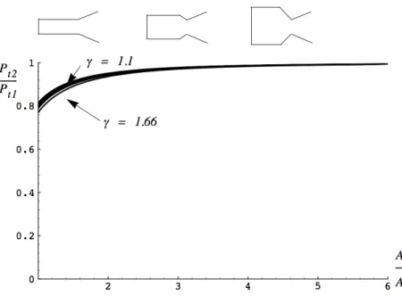
The relations (7.53) and (7.54) e↵ectively define a relationship between A2/A⇤, Pt2/Pt1
and P2/P1, plotted in Figure 7.5 for several values of .
The desire to keep stagnation pressure losses relatively small, while avoiding an excessively large diameter combustion chamber, dictates the internal area ratio selected for the com-bustion chamber. It is clear from Figure 7.5 that an area ratio of about 3 is sufficient to keep the stagnation pressure losses across the combustion chamber negligibly small. Practically all rocket thrust chambers have an area ratio of about 3 for this reason.
Figure 7.5: Combustion chamber stagnation pressure loss.
7.8
The Tsiolkovsky rocket equation
Consider the force balance on a rocket in flight shown in Figure 7.6. The variables identified in the figure are as follows.
T =vehicle thrust
D=vehicle aerodynamic drag Vr=vehicle velocity
✓=angle with respect to the horizontal ˙
m=nozzle mass f low Mr =vehicle mass
g=gravitational acceleration
(7.55)
The balance of forces along the direction of flight was derived earlier. Here we add the gravitational component of the force balance
Mr dVr
dt =T MrgSin(✓) D (7.56) or
Figure 7.6: Rocket free body diagram. Mr dVr dt = C dMr dt MrgSin(✓) D (7.57) whereC is the e↵ective exhaust velocity. Divide (7.57) through byMr.
dVr dt = C d(lnMr) dt gSin(✓) D Mr (7.58) Let Mri=initial mass at t= 0 Mrf =f inal mass at t=tb tb=time of burnout. (7.59)
Integrate (7.58) assuming constantC. The velocity change of the vehicle is
Vr =Vrb Vr0 = Vr|ideal Vr|gravitational Vr|drag (7.60) where Vr|gravitational= Z tb 0 gSin(✓)dt Vr|drag = Z tb 0 ✓ D Mr ◆ dt. (7.61)
For a typical launch vehicle headed to orbit, aerodynamic drag losses are generally quite small on the order of 100 to 500m/sec. Gravitational losses are larger, generally ranging from 700 to 1500m/sec depending on the shape of the trajectory to orbit. By far the largest term is the equation for the ideal velocity increment
Vr|ideal=Cln ✓ Mri Mrf ◆ (7.62) first derived in 1903 by the soviet rocket pioneer Konstantin Tsiolkovsky who is credited with developing much of the early theory of rocket flight. Equation (7.62) shows the de-pendence of the velocity achieved by a rocket on the e↵ective exhaust velocity (determined by the choice of propellants) and the initial to final mass ratio which is determined by what might be termed the structural efficiency of the vehicle and the density of the propellants. Notice the similarity of (7.62) to the Bruguet range equation discussed in chapter 2. In general, one seeks a very lightweight vehicle to carry high density propellants which after combustion produce very lightweight products. In practice these requirements conflict. Generally solid rockets use relatively dense, low energy propellants which do not produce very lightweight products of combustion. Whereas liquid rockets use more energetic pro-pellants that produce light products but are not particularly dense.
7.9
Reaching orbit
Orbital velocity at an altitude of 115 miles, which is about the lowest altitude where a stable orbit can be maintained, is approximately 7777m/sec. To reach this velocity from the Kennedy Space Center where the velocity due to the rotation of the Earth is approximately 427m/sec, assuming gravitational plus drag losses of 1700m/sec, requires an ideal velocity increment of 9050m/sec. A hydrogen-oxygen system with an e↵ective average exhaust velocity (from sea- level to vacuum) of 4000m/sec would require Mi/Mf = 9.7. This represents a very high level of structural efficiency and is the fundamental challenge being addressed by single-stage-to-orbit concepts. At the present time existing launch vehicles require multiple stages to achieve orbit with a reasonable payload size.
Strategies for reducing gravitational losses are mainly limited to optimizing the trajectory to orbit and expending the maximum amount of propellant as possible near the earth’s sur-face (to avoid the work required to lift it to altitude). The latter strategy suggests that the most efficient way to orbit would be an artillery shell, however practical limitations prevent large acceleration loads on the payload. Most large launch vehicles are relatively delicate and require throttling back on thrust at low altitude to avoid large dynamic pressure loads on the vehicle.
The drag losses can be minimized by designing a slender vehicle. This can be seen as follows Vr|drag = Z tb 0 ✓ D Mr ◆ dt= Z tb 0 1 2 ⇢Vr2ACD Mri ✓ Mri Mr ◆ dt= A 2Mri Z tb 0 ⇢Vr2CD ✓ Mri Mr ◆ dt (7.63) whereAis the cross-sectional area of the vehicle. The integral on the right-hand-side is ap-proximately independent of vehicle size and the initial mass of the vehicle is apap-proximately proportional to the vehicle volume, Mri ⇠=⇢vehicleVvehicle.
Vrocket|drag ⇠= F rontalArearocket 2densityrocketV olumerocket Z tb 0 ⇢Vrocket2CD ✓ Mrocketi Mrocket ◆ dt⇠ 1 Lengthrocket (7.64) The last result suggests that the vehicle should be long and thin, roughly like a pencil. Note that the drag losses go down as the mass goes up, and so the velocity loss due to drag tends to become smaller as the vehicle absolute size goes up. The length to diameter ratio of the vehicle does not come into the analysis directly but, in general, the drag coefficient, Cd, decreases as theL/D goes up.
7.10
The thrust coefficient
The thrust coefficient provides a useful dimensionless measure of engine thrust.
CF = T Pt2A⇤ = mU˙ e+ (Pe P0)Ae Pt2A⇤ = ✓ Pe Pt2 ◆ ✓ Ae A⇤ ◆ ✓ Me2+ 1 P0 Pe ◆ (7.65) This rather complicated looking expression can be written in terms of the nozzle exit Mach number and pressure
CF = ⇣ 1 +1 2 ⌘ +1 2( 1) ⇣ Me2+ 1 P0 Pe ⌘ Me⇣1 + 21Me2⌘ 1 2 (7.66)
where the nozzle flow has been assumed to be isentropic. For a rocket operating in a vacuum, with a very large expansion ratioMe!large, the thrust coefficient has an upper limit of
CFmax = ⇣ 1 2 ⌘1 2⇣ +1 2 ⌘ +1 2( 1) . (7.67)
The thrust coefficient is plotted in Figure 7.7 for several values of as a function of exit Mach number.
Figure 7.7: Thrust coefficient versus Mach number.
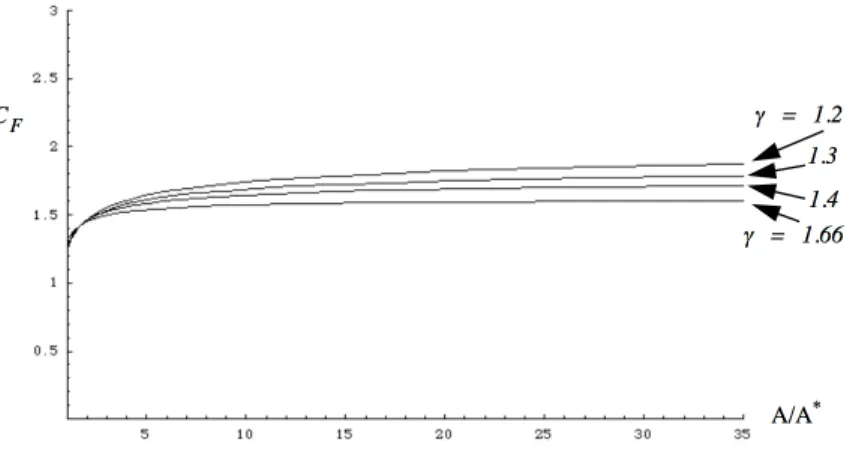
The thrust coefficient is also plotted in Figure 7.8 for several values of as a function of nozzle exit area ratio.
Figure 7.8: Thrust coefficient versus area ratio.
The thrust coefficient gives us a useful measure of the e↵ect of nozzle expansion on thrust. It is clear from Figure 7.7 that, in principle, expanding a gas with low would have the greatest benefit. However Figure 7.4 indicates that a large area ratio nozzle is required to
reach the high exit Mach number required to obtain this benefit. We can see from Figure 7.7 and Figure 7.8 that fully expanding the flow, versus no expansion at all (a simple convergent nozzle), represents as much as a 50 % increase in the thrust generated by the nozzle. Generally, high temperature combustion gases have values of between 1.2 and 1.3 with the lower values characterizing high molecular weight products of combustion typical of solid rockets.
7.11
Problems
Problem 1- A monopropellant thruster using Argon gas at 100psiaand 1500K exhausts through a large area ratio convergent-divergent nozzle to the vacuum of space. Determine the energy per unit mass of a parcel of gas at three locations: in the plenum, at the nozzle throat, and at the end of the expansion where the gas pressure approaches vacuum. What mechanism is responsible for the change of energy from one position to the next? How does your answer change if the gas is changed to Helium?
Problem 2 - The designer of a spacecraft maneuvering system needs to choose between
Argon (atomic weight 40) and Helium (atomic weight 4) as propellants for a monopropellant thruster. The gas pressure and temperature in the propellant tank are 5⇥106N/m2 and 300Krespectively. The propellant tank volume is 1.0m3and the empty mass of the vehicle is 10kg.
1) Which propellant gas will give the largest velocity change to the vehicle? Estimate the vehicle velocity change for each gas?
2) Suppose the vehicle mass is 1000kg, which propellant would deliver the largest velocity change?
Problem 3 - Consider two di↵erent systems used for space propulsion. System A uses propellants with an average density of 2gm/cm3and specific impulse of 200 seconds while system B uses propellants with an average density of 1gm/cm3 and specific impulse 300 seconds. The ideal velocity increment generated by either system is given by
V =Ispg0ln ✓ minitial mf inal ◆ (7.68) whereg0= 9.8m/sec2. Two missions are under consideration.
1) Mission I involves maneuvering of a large satellite where the satellite empty mass (mfinal ) is 2000 kg and the required velocity increment is 100 m/sec.
2) Mission II involves a deep space mission where the vehicle empty mass (mf inal) is 200kg and the required velocity increment is 6000m/sec.
The design requirement in both cases is to keep the tank volume required for the propellant as small as possible. Which propellant choice is best for each mission?
Problem 4- Recently one of the popular toys being sold was called a stomp rocket. The launcher consists of a flexible plastic bladder connected to a 1.5cm diameter rigid plastic tube. The rocket is a slightly larger diameter rigid plastic tube, closed at the top end, about 20cmlong. The rocket weighs about 10gm. The rocket slips over the tube as shown in Figure 7.9.
Figure 7.9: Stomp rocket toy.
Jumping on the bladder pressurizes the air inside and launches the rocket to a height which the manufacturer claims can exceed 50m. The area of the bladder in contact with the ground is approximately 100cm2. Use basic principles of mechanics to roughly estimate how much a child would have to weigh to be able to achieve this height.
Problem 5 - Consider a class of monopropellant thrusters based on the use of the noble gases including Helium (Mw = 4), Neon (Mw= 20), Argon (Mw= 40), Krypton, (Mw = 84) and Xenon (Mw = 131). Radon (Mw = 222) is excluded because of its radioactivity. The thruster is comprised of a tank that exhausts through a simple convergent nozzle to the vacuum of space. Onboard heaters are used to maintain the gas in the tank at a constant stagnation temperatureTt2 as it is exhausted.
1) The thrust is often expressed in terms of an e↵ective exhaust velocityT = ˙mC. Show that the e↵ective exhaust velocity of this system can be expressed as
C= ✓ 2 ( + 1)✓Ru Mw ◆ Tt2 ◆1/2 . (7.69)
2) The mass of propellant contained in the tank is
Mpropellant=
Pt2initialVtankMw RuTt2
. (7.70)
The initial tank pressure is some rated value (a do-not-exceed pressure) independent of the type of gas used. The designer would like to choose the propellant gas so that the velocity increment produced by the propulsion system V is as large as possible for fixed tank volume, initial pressure and gas temperature. The problem is to decide whether to choose a gas with low Mw, thus achieving a high value of C but low propellant mass, or a gas with highMw reducing C but increasing propellant mass. By mixing two or more gases, any mean atomic mass between 4 and 131 can be selected by the designer. Note that is the same regardless of what gas or mixture of gases is used.
Show that the maximum V occurs when the ratioMpropellant/Mstructureis approximately 4 (actually 3.922). In other words, once the tank volume, pressure and temperature are determined and the vehicle empty mass is known, show that for maximum V the gas should be selected to have a mean atomic weightMw such that
Pt2initialVtankMw RuTt2Mstructure
= 3.922. (7.71)
Problem 6 - The space shuttle main engine has a nozzle throat diameter of 10.22in
a nozzle area ratio of 77.5 and produces 418,000 pounds of thrust at lift-o↵ from Cape Canaveral. Determine the engine thrust when it reaches the vacuum of space.