2115. Fuzzy control of active suspension system
Senthilkumar Palanisamy1, Sivakumar Karuppan2
Bannari amman Institute of Technology, Sathyamangalam, India
1Corresponding author
E-mail:1bitsenthil@gmail.com, 2ksksiddharth@gmail.com
Received 6 December 2015; received in revised form 12 March 2016; accepted 22 April 2016 DOI http://dx.doi.org/10.21595/jve.2016.16699
Abstract. The main objective of this paper is to investigate the performance of active suspension system, using suspension deflection of the vehicle body as the principal criterion of control and fuzzy-logic as the control scheme. This work describes the application of fuzzy logic technique to the control of a continuously damping automotive suspension system. Active suspension systems are multivariable dynamic systems for which it is difficult to derive mathematical models. Therefore, analytical control schemes based on such models are complex to construct and generally do not perform well in practice. Hence intelligent control schemes like fuzzy logic controllers that can control the un modelled part of the suspension dynamics are simple to realize and can yield accurate control. This paper has described a proposed fuzzy control scheme for suspensions of the vehicle, because of its inherent ability to represent dynamics, the controller is easy to adapt for control tasks. The paper also describes the model and controller used in the study and discusses the vehicle response results obtained from a range of road input simulations. The simulation results obtained have confirmed the feasibility of the proposed fuzzy control scheme in Active suspension system.
Keywords: fuzzy, PID, active suspension. 1.Introduction
A suspension system plays a vital role in vehicle’s road handling and holding capacity by segregating the vehicle body from the road bumps and vibrations. Since the vehicle suspension system is important to the ride, comfort, and driving capability, design of a better quality suspension system for rough road surface condition is an important development objective for current automotive industry. An ideal vehicle suspension system should have the capability to reduce sprung mass displacement and acceleration and provide adequate suspension deflection to maintain tire-terrain contact. Since late 1970s, many types of suspension systems: passive [1, 2], semi-active [3] and active [4, 5] has been investigated and successfully implemented. Nowadays, more attention is being paid to the active system due to the fact that active suspensions have a potential to meet the performance requirements demanded by users. Various approaches have been discussed in order to design suitable control strategy for these active suspension systems. In recent years, the investigations of active suspension are being continued. Many researchers have been working on control strategies in order to improve the vibro-isolating properties of active suspension systems.
In all kinds of suspension systems, active suspension systems are more effective than others, such as passive or semi active suspension systems. Active suspension systems generally exhibit nonlinear and complex characteristics, so their mathematical models are difficult to accurately identify. Consequently, it is impractical to design model-based controllers for the control of active suspension systems. Fuzzy logic controller (FLC), based on fuzzy sets [6], are designed without system models for the development of the controllers and have been extensively employed to improve the control performances of active suspension system [7-9].
FLC can be designed based on some knowledge or without any knowledge about the control system. In addition, an appropriate fuzzy logic controller can overcome the environmental variation during operation processes. Therefore, it has been employed in the field of active suspension system. Fuzzy logic was first proposed by Lotfi A. Zadeh in 1965 and then he elaborated on his ideas in 1973 and introduced the concept of “linguistic variables”, Ro et al. [10]
developed a fuzzy logic algorithm for an active ride comfort of a quarter-car model. Yester and Mcfall [11] and Cherry and Jones [12] employed fuzzy logic strategy for controlling an automotive suspension incorporating active elements. Huang and Chao [13-17] proposed a fuzzy control scheme to remove tire deformation from the control variable using a grey predictor for improving the control performance. However, the design of a traditional fuzzy controller depends fully on an expert or the experience of an operator to establish the fuzzy rules bank. There is no guide rule for designing the fuzzy rules bank and parameters [17-20]. Here FLC is designed with the objective to suppress the displacement and acceleration in the sprung mass so as to improve the service life of the suspension system and the ride quality of the car. The methodology is applied to a quarter-car suspension system. The remaining part of this paper is organized as follows. Section 2 contains a description of modeling for the suspension system. The control problem and the Controller designs is presented in Section 3. The resulting simulation are given in Section 4, and the conclusions in Section 5.
2.Modeling of suspension system 2.1.Mathematical modeling
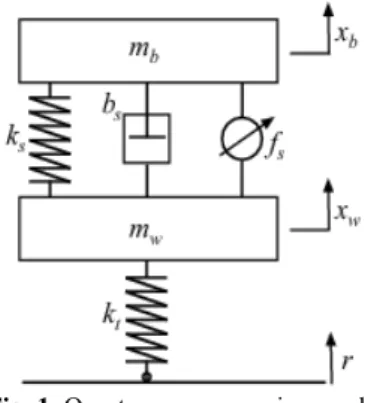
Fig. 1 shows a quarter-car model of the suspension system. The sprung mass represents the vehicle body, and the unsprung mass is an assembly of the axle and wheel. The tire is assured to contact the surface of the road when the vehicle is traveling, and is modeled as a linear spring with stiffness . The linear damper, whose average damping coefficient is , and the linear spring, whose average stiffness coefficient is , consist of the passive component of the suspension system. The actuation force is acting between the sprung and unsprung masses. The state variables and are the vertical displacements of the sprung and unsprung masses, respectively, and r is the vertical road profile. Table 1 lists the parameters of the active suspension system.
Fig. 1. Quarter car suspension model
Table 1. Parameter values of active suspension system
Parameter Value
Sprung mass ( ) 290 kg
Unsprung mass ( ) 59 kg
Damping coefficient of damper ( ) 1000 N/m/s
Stiffness of damper ( ) 16,812 N/m
Stiffness of tyre ( ) 190,000 N/m
Actuation force ( ) 10000 N
2.2.System description
The dynamics for the suspension system, excluding the actuator and when the suspension travel is below its physical limit, is described by the linear Eq. (1) and (2):
+ − ) + − ) = , (1)
+ − ) + − ) + − ) = − , (2)
where indicate the body acceleration; refers to the wheel acceleration; refers to wheel velocity; refers to actuator force. The motion equations of the quarter car model for active suspension can be written in state space form as follows:
= 0 1 0 0 − − 0 0 0 1 − − − − + 0 0 0 0 0 − .
The output of the system in state space is represented as:
− .. = 1 0 0 0 1 0 −1 0 − − − − + 0 0 0 0 − .
3.Intelligent controller design
The whole premise behind intelligent control is that the system to be controlled does not have to be rigidly modelled. This is the biggest distinction between intelligent control and classical control. Here the designer only has to give the appropriate stimuli as input to the intelligent control and evaluate it based on its output. The intelligent control itself develops a model of the system to be controlled. Fuzzy logic, like most of the IC techniques attempts to model the way of reasoning that goes on in the human brain. It is based on the idea that the human reasoning is approximate, non-quantitative, and non-binary. In many cases, there is no black and white answer, but shades of grey.
3.1.Control problem
The control objective is to maximize the passenger comfort, while preserving the lifetime of suspension components, under road disturbances. The comfort is determined by the level of vertical car body acceleration experienced by the passenger. The lifetime of components is preserved by avoiding hitting of the rattle-space limits. Hence, the controller objectives can be stated as (a) increase, with respect to open-loop, the range of “typical” road disturbances for which the suspension travel limits are not reached, and (b) minimize the peaks of the body accelerations under road disturbances.
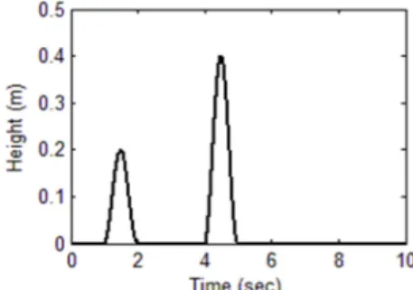
A road input, as described by Eqs. (3)-(5), is used to simulate the road to verify the developed control system. The road input described by as follow:
= −0.1, 0 ≤ ≤ 10,0, otherwise, (3) = 0.1 1 − cos 2 ) , 1 ≤ ≤ 2, 0.4 1 − cos 2 ) , 2 ≤ ≤ 4, 0 otherwise, (4) ) = √Δ 2 10 Δ cos 2 Δ + ), (5)
where: is the abscissa variable from 0 to ; = 250 m; Δ = 1/ ; = 1/ ;
= /Δ = / ; is a constant value depending from ISO road profile classification, it
assumes integers increasing from 3 to 9, corresponding to the profiles from class A to class H; = 0.1 cycles/m; random phase angle following an uniform probabilistic distribution within the 0-2 range [21-22].
3.2.Fuzzy controller
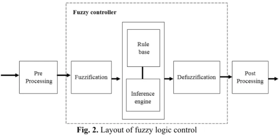
The Fuzzy Logic Controller [10, 11] used in the active suspension has two inputs say body error ( ), change in error ( ) of suspension travel and one output which has desired actuator force . The control system itself consists of three stages: fuzzification, fuzzy inference machine and defuzzification. The fuzzification stage converts real-number (crisp) input values into fuzzy values, while the fuzzy inference machine processes the input data and computes the controller outputs based on rule base and the data base. These outputs, in fuzzy values, are converted into real-numbers by the defuzzification stage.
Fig. 2. Layout of fuzzy logic control
The schematic of fuzzy controller for active suspension is shown in Fig. 2. The process of converting a numerical variable into a linguistic variable (fuzzy number) is called Fuzzification. Under Fuzzy inference, the truth value for the premise of each rule is computed, and applied to the conclusion part of each rule. This results in one fuzzy subset to be assigned to each output variable for each rule. Mostly MIN or PRODUCT is used as inference rules. In MIN inference, the output membership function is clipped off at a height corresponding to the rule premise’s computed degree of truth (fuzzy logic AND). A possible choice of the membership functions for the mentioned variables of the active suspension system represented by a fuzzy set is as shown in Figs. 3 to 5.
Fig. 3. Membership function for error Fig. 4. Membership function for change in error
For the rule basis, a classic interpretation of Mamdani was used. Under rule base, rules are constructed for outputs. The rules are in “If Then” format and formally the “If” side is called the conditions and the “Then” side is called the conclusion. A rule base controller is easy to understand and easy to maintain for a non- specialist end user and an equivalent controller could be implemented using conventional techniques. The rules table for fuzzy logic control is shown in Table 2.
The rule base used in the active suspension system can be represented by the following Table 2 with fuzzy terms derived by modelling the designer’s knowledge and experience.
Table 2. Fuzzy rules table
C/Ce NB NM ZE PM PB NB NB NB NM NM Z NM NB NM NM ZE PM ZE NM NM Z PM PM PM NM ZR PM PM PB PB ZR PM PM PB PB
The abbreviations used correspond to: NB: Negative Big; NM: Negative Medium; ZE: Zero; PM: Positive Medium; PB: Positive Big; e: Error; ce: Change in error
Defuzzification is a process of converting fuzzy output to crisp number. There are more Defuzzification methods in which one of the most common technique is centroid methods. In the centroid method, the crisp value of output variable is computed by finding the variable value of the centre of gravity of membership function for the fuzzy value. This technique was developed by Sugeno in 1985. The only limitation of this method is that it is computationally difficult for complex membership functions [31]. The centroid defuzzification technique can be expressed as:
= )
) ,
where is the crisp output, ) is the aggregated membership function and is the output variable.
4.Simulation
The performance of the proposed fuzzy control scheme is illustrated in this section through a series of simulations. Simulation results are carried out using a quarter car model with active suspension, with two different road profile , as shown in Figs. 6, 7 to demonstrate the efficiency of the proposed Fuzzy controller. For comparison purposes, the numerical results of the vehicle model with PID controller are also presented. PID control is perhaps the most widely used control method. It can provide fast response, well system stability and small steady state errors in a linear system with known parameters.
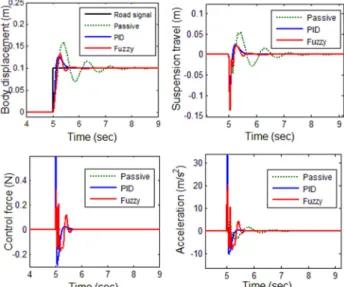
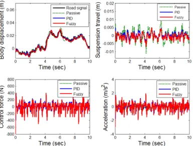
The result of the simulation of Fuzzy controller for road input is shown Fig. 8. The four representative variables for controller evaluation are body displacement, suspension travel, Control force, body acceleration. From the Body Displacement, the settling time of passive suspension system is not stable and overshoot is very big. The output has an overshoot more than 20 % and settling time is long and not stable. Using the Fuzzy controller for suspension system, the results of overshoot is small and the settling time is also short. The suspension travel has an overshoot less than 20 % and a settling time shorter than 1 sec. The ride comfort is also improved by means of the reduction of the body acceleration with the help of fuzzy control scheme.
Fig. 8. Response of suspension system for road input signal
Fig. 9. Response of suspension system for road input signal
The results are shown Fig. 9 for the case with the road profile . Here, the overshoot and settling time are not acceptable for passive suspension. The system has the suspension travel with overshoot more than 50 % and a settling time longer than 3 sec. The fuzzy controlled system has less overshoot and settling time less than 1sec which indicates the efficiency of the proposed controller. The decrease in body acceleration magnitudes assures improved ride comfort as
presented in body acceleration. There is not any permanent offset in suspension deflection which indicates that the proposed fuzzy control method is a suitable choice for implementation in active suspension.
The results are shown Fig. 10 for the case with the road profile . The fuzzy controlled system has less overshoot and settling time which indicates the efficiency of the proposed controller. It is seen that by using the proposed fuzzy controller the magnitudes for both vertical displacement and acceleration of the vehicle body are decreased significantly while passive suspension increased the magnitudes of both displacement and acceleration of the vehicle body. These results indicate that the ride comfort of the passengers is improved greatly by using the proposed FL controller.
Fig. 10. Response of suspension system for road input signal
5.Conclusion
Active suspension systems are multivariable dynamic systems for which it is difficult to derive mathematical models. Therefore, analytical control schemes based on such models are complex to construct and generally do not perform well in practice. On the other hand, intelligent control schemes like fuzzy logic controllers that can control the unmodelled part of the suspension dynamics are simple to realize and can yield accurate control. This paper has described a proposed fuzzy control scheme for suspensions of the vehicle, because of its inherent ability to represent dynamics, the controller is easy to adapt for control tasks. The simulation results obtained have confirmed the feasibility of the proposed fuzzy control scheme in Active suspension system, Further work should be considered if a robust adaptive fuzzy controller is to be designed for optimization of fuzzy rules.
References
[1] Thompson A. G. Optimum damping in a randomly excited non-linear suspension. Proceedingsof the Institution of Mechanical Engineers, 1969, p. 169-184.
[2] Karnopp D. Analytical results for optimum actively damped suspensions under and excitation. ASME Journal of Vibration, Stress, and Reliability in Design, 1989, p. 278-283.
[3] Crolla D. A. Semi-active suspension control for a full vehicle model. SAE Technical Paper Series, 1992, p. 45-51.
[4] Goodall R. M., Kortm W. Active controlling round transportation – review of the state-of-the-art and future potential. Vehicle System Dynamics, Vol. 12, 1983, p. 225-257.
[5] Hrovat D. Optimal active suspensions for 3d vehicle models. Proceedings of the American Control Conference, Arizona, USA, Vol. 2, 1991, p. 1534-1541.
[6] Zadeh L. A. Fuzzy sets. Information and Control, Vol. 8, Issue 3, 1965, p. 338-353.
[7] Kuo Y. P., Li T. S. S. GA-based fuzzy PI/PD controller for automotive active suspension system. IEEE Transactions on Industrial Electronics,Vol. 46, Issue 6, 1999, p. 1051-1056.
[8] Lee S., Kim W. J. Active suspension control with direct-drive tubular linear brushless permanent-magnet motor. IEEE Transactions on Control Systems Technology, Vol. 18, Issue 4, 2010, p. 859-870.
[9] Cao J., Li P., Liu H. An interval fuzzy controller for vehicle active suspension systems. IEEE Transactions on Intelligent Transportation Systems,Vol. 11, Issue 4, 2010, p. 885-895.
[10] Ro P. L., Kim C., Kim H. Active suspension using fuzzy logic control. Proceedings of the American Control Conference, 1993, p. 2252-2253.
[11] Yester J. L., Mcfall R. H. Fuzzy Logic controller for active suspension. SAE Papers, 1992, p. 259-270.
[12] Cherry A. S., Jones R. P. Fuzzy logic control of automotive suspension systems. IEE Proceedings - Control Theory and Applications, Vol. 142, Issue 2, 1995, p. 149-160.
[13] Huang S. J., Chao H. C. Fuzzy logic controller for a vehicle active suspension system. Proceedings of the Institution of Mechanical Engineers, Part D: Journal of Automobile Engineering,Vol. 214, 2000, p. 1-12.
[14] Hrovat D. Survey of advanced suspension developments and related optimal control applications. Automatica, Vol. 33, Issue 10, 1997, p. 1781-1817.
[15] Williams R. A. Automotive active suspensions. Part 1: basic principles. Proceedings of the Institution of Mechanical Engineers, Vol. 211, Issue 6, 1997, p. 415-426.
[16] D’AmatoF. J., Viassolo D. E. Fuzzy Control for Active Suspensions. Technical Report, Purdue University, Indiana, 1998.
[17] Passino K. M., Yurkovich S. Fuzzy Control. Addison Wesley Longman, Inc., California, 1998.
[18] Driankov D., Hellendoorn H., Reinfrank M. An Introduction to Fuzzy Control. Springer-Verlag, Berlin, Germany, 1993.
[19] Rao M. V. C., Prahlad V. A tunable fuzzy logic controller for vehicle active suspension systems. Fuzzy Sets and Systems, Vol. 85, Issue 1, 1997, p. 11-21.
[20] Yeh E., Tsao Y. A fuzzy preview control scheme of active suspension for rough road. International Journal of Vehicle Design, Vol. 15, Issue 1, 1994, p. 166-180.
[21] Cebon D. Handbook of Vehicle Road Interaction. Swets and Zeitlinger, Lisse Netherlands, 1999.
[22] Park S., Popov A. A., Cole D. J. Influence of soil deformation on off-road heavy vehicle suspension vibration. Journal of Terramechanics, Vol. 41, Issue 1, 2004, p. 41-68.
Senthilkumar Palanisamy received M.E. degree in Engineering Design from College of Engineering – Guindy campus in 2010. Now he is working as an Assistant Professor, Department of Mechanical Engineering, Bannari amman Institute of Technology, Sathyamangalam. His current research interests include vehicle dynamics, fuzzy control and active vibration control.
Sivakumar Karuppan received Ph.D. degree in Production Engineering from Bharathiyar University in 2007. Now he is working as a Professor in Mechanical Engineering at Bannari amman Institute of Technology, Sathyamangalam. His current research interests include optimization of machine parameter, particle swam optimization, intelligent optimization techniques.