Towards a ground navigation system based in visual feedback provided
by a mini UAV
Mario Garz´on
∗, Jo˜ao Valente, David Zapata, Rigoberto Chil and Antonio Barrientos
Abstract— This paper addresses initial efforts to develop a navigation system for ground vehicles supported by visual feedback from a mini aerial vehicle. A visual-based algorithm computes the ground vehicle pose in the world frame, as well as possible obstacles within the ground vehicle pathway. Relying on that information, a navigation and obstacle avoidance system is used to re-plan the ground vehicle trajectory, ensuring an optimal detour. Finally, some experiments are presented employing a unmanned ground vehicle (UGV) and a low cost mini unmanned aerial vehicle (UAV).
I. INTRODUCTION
Mobile robotic systems, both aerial and terrestrial have been studied and developed over the years for several civil and military purposes. Some of those applications are fo-cused on using mobile robots to help or substitute in tedious or dangerous tasks, as well as to survey and patrol large unstructured environments. This task is one of the objectives of the ROTOS project in which this work is framed.
In order to perform perimeter surveillance, a robot must be able to generate a trajectory to explore, or to navigate from an initial to a final point without colliding with other vehicles or obstacles. This autonomous navigation is one of the most ambitious issues in the robotics research.
Concerning to visual navigation, many reactive and delib-erative navigation approaches have been presented up to now, e.g. in structured environments using white line recognition [5], in corridor navigation using View-Sequenced Route Representation [7], or more complex techniques combining visual localisation with the extraction of valid planar region [3], or visual and navigation techniques to perform visual navigation and obstacle avoidance [2].
Aerial and ground robots have the peculiarity to be en-dowed with different characteristics. By merging all those capacities and characteristics together, it is possible to de-velop a unique sensing and perception collaborative system. Some of those studies have been applied in several differ-ent contexts, such as, environmdiffer-ent monitoring [4], pursuit-evasion games [12], fire detection and fighting [8], multi-robot localisation in highly cluttered urban environments [1], de-mining [6], and other multi-purpose collaborative tasks [11].
In this paper a strategy that takes advantage of a mixed robotic system heterogeneity for collaborative navigation and obstacle avoidance is addressed. In other words, the ground ∗Corresponding author. Mario Garz´on is with Robotics &
Cybernet-ics group (CAR UPM-CSIC), Universidad Polit´enica de Madrid (ETSII-DISAM), C/ Jos´e Guti´errez Abascal, 2, Spain.
ma.garzon at upm.es
robot navigation is supported by visual data from the aerial robot.
One of the advantages of using an aerial visual navigation system is that the UGV field of view (FOV) is dynamic. This means that by controlling the UAV height and relative position, the UGV at some stage can do a pseudo-zoom on an obstacle or any interesting object, as well as reconnaissance of areas outside the UGVs FOV. Moreover, it is also possible to identify rugged terrain, floor openings or negative ob-stacles, and other unexpected navigation obstructions in the UGV surrounds. This collaboration ensures the UGVs safety while it performs other inspection tasks. Finally, the system does not require previous knowledge from the environment and it can cover large navigation perimeters.
The free collision navigation system is being developed in several phases. In the first step, the UGV and the obstacles in the robot pathway are discriminated from the aerial image, then techniques based in potential fields are applied to enable simple navigation and obstacle avoidance. The proposed architecture will allow in later phases to build local-maps and obtain a geo-referenced position of the obstacles seen by the UAV. Also, each obstacle found can be memorised and a global map with all obstacles will be built. This will enable the system to merge reactive and deliberative methods.
This paper is organized as follows. First, the problems regarding geometric projections, UGV navigation and control are stated. In the next section the robotic components, the system architecture and middleware used for communica-tions and control are described. After that the solucommunica-tions proposed for features extraction and ground navigation are addressed. Finally, the first results obtained and the conclu-sions are presented.
II. PROBLEM FORMULATION
This section describes the projections and coordinate sys-tem changes that are necessary to use the image obtained with the camera shipped on-board the UAV for detecting the UGV and the obstacles surrounding it. Hence, the UGV will be a dynamic point in the environment and the obstacles static points.
The goal herein is, first of all, to obtain the relative dis-tance from the UGV to any unexpected obstacle surrounding it. Secondly, it is to build a map with all obstacles. A global map with the location of the obstacles in relation to the world frame is built by geo-referencing the obstacles extracted from each image frame (i.e. local-mapping)1.
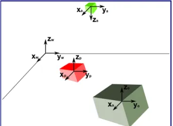
The reference frame system adopted by the aerial-ground robotics system is shown in Figure 1.
Fig. 1: Coordinate frames: (w) world, (p) UGV, (o) obstacle, and (a) UAV.
The UGV location with relation to the obstacle frame is given by pPo, which can be denoted as the distance from the UGV to the obstacle in the imageI ∈(u,v)(given in pixels).
Let’s consider, (pxp,pyp) and (pxo,pyo) the UGV and
obstacle position in the image. And also, op, and oo the orientation of the UGV and the obstacle obtained from the image2. So, it’s true that,
pP
o= (pxo,pyo)−(pxp,pyp)
pO
o=oo−op
(1)
To obtain pPo in meters, the intrinsic and extrinsic pa-rameters from the camera must be considered. Additionally, the height that the UAV flies over the UGV is assumed to be constant and known, also since the dynamics from the UAV are much faster than the UGV’s the image is assumed to be completely vertical. Altough future versions of the system could take into account the UAV’s attitude in the calculation of the homography. The distance from the UGV to the obstacles in metric units is obtained from the simplified pinhole camera model. The Equation is given in 2. whereZa is the UAV height above the UGV, dp in pixels, and f the focal length.
pP0
o[m] =d=
−Za×dp
f (2)
Finally, but not least, a simple reactive control law can be derived from Eq. 1. Let’s consider the vehicle kinematics as following:
2The orientation in the image frame is obtained with relation to the center
of the image ˙ x= v1+v2 2 cosθ ˙ y= v1+v2 2 sinθ ˙ θ= v2−v1 2l (3)
,wherev1,v2, are respectively the velocity of each wheel, θ its orientation, andl the length of the wheel. The control law is given by,
vx( ˙x, x) = (pxo−pxp)×Kpvx
vy( ˙y, y) = (pyo−pyp)×Kpvy
θ( ˙x,y˙) = (oo−op)×Kpo
,where Kpvx,vy ,o∈ <
(4)
On the other hand, the UGV position in the world frame is given by wP
p = [xp, yp]T and orientation wOp = ψp, which are given by the GPS and compass respectively.
The local map is built by identifying the obstacle in the image and obtained its position with reference to the world frame. This is the same to say that geo-referenced images are obtained in real time, and in this way also the obstacle’s global position can be found.
An obstacle is located in the world reference frame with a position and orientation3 defined by wP
o = [xo, yo]T and wO
o=ψo. Explicity, wP
o=wPp×pPo (5)
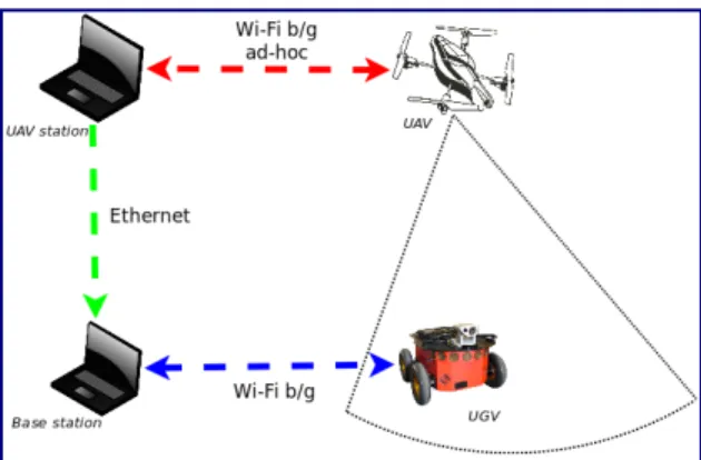
III. AERIAL-GROUND ROBOTIC SYSTEM In this section the proposed Aerial-Ground robotic system is presented; the two robotic systems observed in the figure 2 are described in the first subsections, then the software archi-tecture and communications middleware is also explained.
Fig. 2: Proposed robotic system.
A. Robots, sensors and communications
As previously mentioned, the aerial-ground robot system has one aerial and one ground robot.
The UGV is a Pioneer3-AT with skid steering, it has an embedded a on-board computational unit, a Wireless Access
Point (WAP), a MT9-B Xsens Inertial Measure Unit (IMU), an uBox GPS, and a Cannon VC-C4 ptz camera. Moreover, the UGV is endowed with a square balsam wood platform with some geometric figures drawn. Those figures have been carefully chosen to help to identify the UGV position and orientation from the aerial image. Finally, it can be also work as an auxiliary landing platform.
The mini UAV adopted is a low cost AR Drone Parrot; It has a weight between 380 and 420 grams depending on the hull. It can fly at a maximum speed of 18 meters per second and a autonomy of fly near to 12 minutes. Its on-board computer system is a processor ARM9 RISC 32-bit 468 MHz with 128 MB DDR RAM memory, Linux OS, and it is communicated via Wi-Fi whose scope on outdoors could be between 50 and 100 meters.
It is equipped with an ultrasonic sensor for altitude measuring with a range of 6 meters; an IMU of 3 axis accelerometer, a 2 axis gyroscope (pitch y roll) and a single axis gyroscope of precision (yaw); and two video cameras, one looking horizontally with 640x480 pixels of resolution, 93 wide-angle diagonal and a 15 fps frequency and the other looking vertically with 176x144 pixels of resolution, 64 wide-angle diagonal and a 60 fps frequency. Although the cameras have a very low resolution, they allow you to process the recognition of the main objects in the environment that interacts with the UGV.
Fig. 3: UAV with external GPS system.
Additionally, the UAV has been endowed with an external wireless GPS system, which provides the quad-rotors latitude and longitude. This hardware add-on has been cocieved to provide more controlabilty and robustness to the UAV (see Figure 3).
B. Middleware architecture
The main idea is to send the video streaming aquired with the UAV on-boar camera through the UAV-station to the base station, that performs a feature extraction, and then to send the location of the relevant objects to the UGV which calculates and applies the navigation control (see Figure 4).
1) UAV - UAV station interface: Using a Wi-Fi ad-hoc connection, the UAV sends navigation data, status, and the images captured by the cameras (one at a time), and receives control commands. By mean of the SDK provided by Par-rot, a user interface has been developed, which integrates
Fig. 4: Aerial-Ground robots communications.
the visualisation of the UAV data, GPS data (way-points visualisation) and an interface for input devices who can control the UAV (e.g. a joystick or a game pad). The Ar drone SDK also features pattern recognition and tracking, although very basic. These features are useful to develop new control algorithms. All this UAV-computer interface has been developed and integrated with the Qt SDK.
2) UGV - Base station interface: The UGV software ar-chitecture has been designed based in ROS. This open-source modular framework provides software libraries, drivers, tools, as well as novel algorithms that help to design complex and efficient robotic systems. The code is maintained by an extended international community and can also be reused [9].
ROS has a message-passing philosophy, which means that each individual ROS package created is able to publish and to subscribe messages of different types, such as velocity commands or sensor reading. Moreover, from now on, a running package is denoted as a node. In a ROS-based system it is also possible to enable communication between nodes running on different computers, by using a single roscore
in one of the machines that provides name registration and lookup to the rest of the Computation Graph.
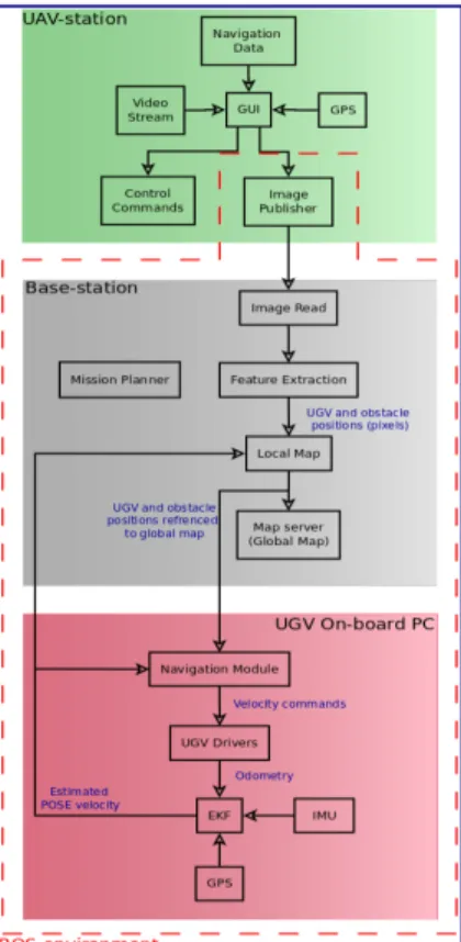
3) The whole system architecture: In order to commu-nicate between both interfaces (that have been developed in different platforms), the UAV station interface has been integrated with the ROS environment by mean of a node that is able to publish the streaming video in a message. That image is read by a node in the base station and theFeature extraction node calculates the UGV and obstacle positions in a raw format (pixels). The nodeLocal Mapis responsible for generating referenced positions and sending them to the UGV. On the UGV on-board computer the Navigation Module node computes the information and generates the velocity for theUGV drivers node that handles the motors and sends feedback with the odometry. The IMU measures and GPS data are also used to close the navigation loop. Finally, the on-board computer sends the information to the base station to correct and generate the geo-referenced map. The Figure 5 shows in detail the whole schema, the ROS-based sub-system is enclosed in the dashed red line.
Fig. 5: Software architecture for the proposed system.
IV. VISUAL-BASED NAVIGATION
This section explains the algorithm used to perform the visual based navigatione; the first step is the processing of the aerial image with the objective of finding the position, size and orientation of the UGV and the possible obstacles in its pathway, and the next subsection describes the algorithm used to perform the navigation and obstacle avoidance in the UGV.
A. Feature extraction
With the aim to obtained the position and orientation from the UGV and the obstacle4 in the camera frame a simple computer vision algorithm was developed. The algorithm pseudo-code is shown below.
Algorithm 1 UGV and obstacle pose extraction algorithm.
1: Countors←F indCountours(Image<gray>)
2: if 4←length(Countors)then 3: R←GetRectangle(Contours)
4: P oint<px,py>←Centroid(R)
5: end if
6: C←HoughCircles(Image<gray>)
7: P oint<px,py>←Centroid(C) 8: pOo←Angle(Rp, Ro)
9: pPo←Distance(Rp, Ro)
The algorithm basically identifies, first of all, rectangular shapes in the image. Then, circles are identified as well.
4in this initial stage just rectangular shape obstacles are identified
As soon as the rectangles and circles are identified, it is possible (through some rules of thumb) to identify the UGV and the obstacle in the image, and also to distinguish them. The algorithm should identify two or three squares and a circle, depending on if there is or not an obstacle in the image. Features extracted examples are depicted in Figure 6. Finally, to obtain the rectangles and the circles, both techniques to find contours and hough transformations were employed.
(a) 6m (b) 3m (c) 1m
Fig. 6: Features extracted at different heights.
B. Potential fields method
The application of this technique to the here proposed robotic system will be an implementation of the steering behaviours [10]. This technique is independent from the locomotion scheme used, and it is based on the definition of a simple vehicle model which is a point mass approximation that allows simple computational model. The vehicle is described by its position, orientation and velocity. Its velocity is modified by applying forces or accelerations (limited by a maximum force parameter).
The velocity is refered to an on-board local reference frame of the UGV. That coordinate system is defined by four vectors, one for the position of the robot and three ortho-normal vectors that define orientation, having the X axis as the normalised direction of the velocity. And since only planar movement is considered the Z axis will be constant, and theY will be the cross product ofX andZ (orForward
andUp). The control signal that is sent to the UGV is one vector quantity, the desired steering force; then it has to be mapped to the control signals for the robot, named linear and angular velocity.
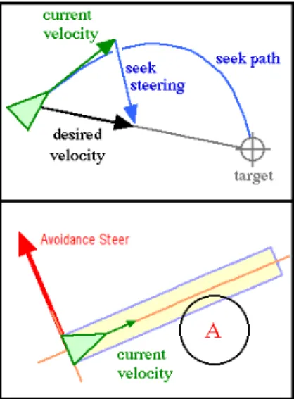
The use of the steering behaviours library for the navi-gation of the UGV has two main advantages: it allows to implement several behaviours for a single UGV or a set of them, and it is possible dynamically to add or remove obstacles, which is very convenient in this case, for this initial effort two steering behaviours were implemented, one for seeking the target point, and another to avoid obstacles. The seeking behaviour tries to steer the vehicle towards a pre-defined position in the global coordinate system, the behaviour adjust the UGV velocity so it is aligned towards the target, the desired velocity is a vector defined from the vehicle position to the target at the maximum speed, the steering vector is the difference between this desired velocity and the UGV current velocity, if seeking behaviour is not modified the UGV will pass through the target and then turn back, a different behaviour called arrival implements a breaking force so the UGV stops at the target.
Fig. 7: Seeking Behaviour - The vectors for desired, current speed and the resulting seeking steer are shown[10].
The avoidance behaviour is intended to provide to the vehicle the ability of manoeuvre in an environment where obstacles may appear, it takes action only when an obstacle is detected in front to the UGV, meaning that if it is moving parallel to a wall, the avoidance will take no action. The basic algorithm assumes that both the vehicle and the obstacles are spheres, although variations can be made to take into account the shape, and then extends the bounding sphere of the UGV to create an imaginary cylinder lying along the forward axis of the UGV, the length of the cylinder depends on the speed of the vehicle and its ability to steer. The algorithm then calculates if any of the given obstacles intersects with the UGV’s cylinder, if there is no collision a zero vector is returned, if a collision is found the center of the obstacle is projected on the side axis of the vehicle and a steer in the opposite direction is generated, if two or more obstacles are found, the one nearest to the vehicle prevails over the rest.
The two behaviours shown in figure 7 where implemented on the UGV’s on board pc, by using the open steer library over the ROS framework, the current position and velocity of the UGV where calculated using an Extended Kalman Filter with the odometry of the robot and the GPS positioning, and the obstacles position is received from the computer vision software also running on ROS, the first results on the test are discussed on the section V.
V. EXPERIMENTS- FIRST RESULTS
This section describes a initial set of tests that were designed and implemented in order to check the feasibility of the system. In a first step the communication between the UAV and the UGV was tested, those tests were imple-mented on an indoor environment, and only hoovering and communications using the middleware described previously were tested, an image of that test is shown in figure 8.
The next test was carried out on an outdoor environment. The objective of the test was to obtain real images from the UAV and test the feature extraction algorithms. Both robots
Fig. 8: First communication and hoovering tests The UAV -UGV communication capability when performing hoovering over the UGV was successfully tested.
were manoeuvred in teleoperation mode and the UGV was equipped the platform described in previous sections. The images obtained from this tests were used to develop the first version of the computed vision algorithm. Once the algorithm was implemented, a final test was executed. In this case the UGV was given a pre-defined and fixed target and obstacle, then an avoidance manoeuvre was executed using the steering behaviours algorithm. The figure 9 shows the trajectory obtained from the odometry of the UGV.
Fig. 9: Odometry from the UGV - The UGV trajectory read from the odometry is shown in blue, additional marks for the target and the obstacle have been added.
By controlling the UAV in hoovering mode over the UGV, images from the aerial vehicle were obtained and processed using the feature extraction algorithm, and the position of the UGV and the obstacle in the image were extracted. At this point no transformations to external frames or geo-reference was performed. The figure 10 show the sequence of aerial images obtained and the objects identified on each frame.
VI. CONCLUSIONS
A visual based ground navigation schema using images from an mini UAV was proposed, the transformations from different coordinate frames were formulated, the software and communication schema were described, and the some
Fig. 10: Aerial Images of the UGV and an Obstacle - Se-quence of images obtained from the UAV while performing an obstacle avoidance manoeuvre.
initial tests using simple feature extraction and control schemas were performed in order to validate the feasibility of the system.
The formulation of the problem shows that it is possible to obtain both the position of the UGV and the obstacles in the field of view of the camera. The communication and the software architecture were successfully tested, and this gives the possibility of applying more complex control algorithms that will allow the system to create a geo-referenced map by combining the visual information from the UAV and the geo-referenced positions from the UGV. The initial tests show that the proposed system and the control techniques can be used to obtain the objective, however more extensive test are needed, as well as more complex controlling and navigation techniques in order to create a more robust measure system.
ACKNOWLEDGEMENT
This work was supported by the Robotics and Cyber-netics Group at Technical University of Madrid (Spain), and funded under the projects ROTOS: Multi-robot system for outdoor infrastructures protection, sponsored by Spain Ministry of Education and Science (DPI2010-17998), and ROBOCITY 2030, sponsored by the Community of Madrid (S-0505/DPI/000235).
REFERENCES
[1] Luiz Chaimowicz, Ben Grocholsky, James F. Keller, Vijay Kumar, and Camillo J. Taylor. Experiments in multirobot air-ground coordination. Inin Proceedings of the 2004 International Conference on Robotics and Automation, pages 4053–4058, 2004.
[2] Andrea Cherubini and Francois Chaumette. Visual navigation with obstacle avoidance. InIntelligent Robots and Systems (IROS), 2011 IEEE/RSJ International Conference on, pages 1593 –1598, sept. 2011. [3] Nguyen Xuan Dao, Bum-Jae You, and Sang-Rok Oh. Visual navi-gation for indoor mobile robots using a single camera. InIntelligent Robots and Systems, 2005. (IROS 2005). 2005 IEEE/RSJ International Conference on, pages 1992–1997, aug. 2005.
[4] Alberto Elfes, Marcel Bergerman, Jos´e Reginaldo Hughes Carvalho, Ely Carneiro de Paiva, Josu´e Jr. Guimares Ramos, and Samuel Siqueira Bueno. Air-ground robotic ensembles for cooperative applications : Concepts and preliminary results. In2nd International Conference on Field and service Robotics, pages 75–80, Pittsburgh, Pa (USA), Aug. 1999.
[5] S. Ishikawa, H. Kuwamoto, and S. Ozawa. Visual navigation of an autonomous vehicle using white line recognition. Pattern Analysis and Machine Intelligence, IEEE Transactions on, 10(5):743 –749, sep 1988.
[6] Erica Zawodny MacArthur, Donald MacArthur, and Carl Crane. Use of cooperative unmanned air and ground vehicles for detection and disposal of mines. volume 5999, page 599909. SPIE, 2005. [7] Y. Matsumoto, M. Inaba, and H. Inoue. Visual navigation using
view-sequenced route representation. InRobotics and Automation, 1996. Proceedings., 1996 IEEE International Conference on, volume 1, pages 83 –88 vol.1, apr 1996.
[8] C. Phan and H.H.T. Liu. A cooperative uav/ugv platform for wildfire detection and fighting. InSystem Simulation and Scientific Computing, 2008. ICSC 2008. Asia Simulation Conference - 7th International Conference on, pages 494 –498, Oct. 2008.
[9] M. Quigley, B. Gerkey, K. Conley, J. Faust, T. Foote, J. Leibs, E. Berger, R. Wheeler, and A. Ng. Ros: an open-source robot operating system. InICRA Workshop on Open Source Software, 2009. [10] C. W. Reynolds. Steering behaviors for autonomous characters. In
Game Developers Conference, 1999 Proceedings, pages 763–782, 1999.
[11] Jo˜ao Valente, Antonio Barrientos, Alexander Martinez, and Christian Fiederling. Field tests with an aerial-ground convoy system for collaborative tasks. In 8th Workshop de RoboCity2030-II: Robots Exteriores, pages 233–248, Madrid, Spain, 2010.
[12] R. Vidal, S. Rashid, C. Sharp, O. Shakernia, Jin Kim, and S. Sastry. Pursuit-evasion games with unmanned ground and aerial vehicles. In Robotics and Automation, 2001. Proceedings 2001 ICRA. IEEE International Conference on, volume 3, pages 2948 – 2955 vol.3, 2001.