Energy Aware Network Optimization
with Aerial Base Stations
Jingcong Sun
A thesis submitted for the degree of Master of Philosophy
of
University College London.
Department of Electronic and Electrical Engineering University College London
2 I, Jingcong Sun, confirm that the work presented in this thesis is my own. Where information has been derived from other sources, I confirm that this has been indicated in the thesis.
Sign:
Abstract 3
Abstract
To meet the fast-growing and highly diversified traffic demand, it is envisioned that unmanned aerial vehicles (UAVs), also known as drones, will become an indis-pensable part in the future communication system. Since UAVs are flexible, cost-effective, fast to deploy and have a better communication condition compared to terrestrial communication system, the use of drones is promising in a wide range of wireless networking applications. By moving closer to the targets, UAVs can act as data collectors to prolong the lifetime of wireless sensor networks (WSNs) or be used as energy transmitters to transfer more energy in wireless power transfer (WPT) scenarios. In particular, UAV based aerial base stations (BSs) have the abil-ity to provide rapid and reliable wireless services wherever and whenever there is an excessive data demand and has become increasingly appealing to network service providers.
In this thesis, we focus on UAVs serving as BSs to provide wireless services to ground users from the sky. Firstly, we consider the power-efficient deployment of multiple static aerial BSs, with the aim of covering a maximum number of ground users while avoiding inter-cell interference (ICI). The proposed techniques achieve an up to 30% higher coverage probability then the benchmark circle packing theory (CPT) when users are not distributed uniformly. In addition, the proposed itera-tive algorithm also greatly improves the power-efficiency by up to 15%. Secondly, by fully exploiting the mobility of UAVs, we study the trajectory and UAV-user scheduling and association of moving aerial BSs. The bottom line aim of UAV ap-plication, where an aerial BS is dispatched to satisfy the data demand of a maximum number of ground users with a given energy budget is considered. It is found that
Abstract 4 the moving aerial BS tends to move close to the targeted ground users to reduce path loss and enjoy a good communication condition. Simulation results show both energy and coverage performance gains for the proposed schemes compared to the benchmark techniques
Impact Statement 5
Impact Statement
The research in this thesis has contributed to the energy-efficient deployment and trajectory design of UAV based aerial BS, which is an indispensable part in future communication systems. From the perspective of academia, this research has stud-ied the bottom line aim of aerial BSs, trying to cover a maximum number of ground users with minimum energy. This research relates to the aims of the MSCA-ITN-ETN project PAINLESS that UCL is coordinating. In fact, this research topic has also attracted the attention of many world-leading companies. Facebook, Nokia-bell labs, China Mobile and Google have successively launched pilot projects to provide wireless services with aerial BSs. In addition, both Qualcomm and AT&T have optimized LTE networks, targeted for possible wide-scale UAV-communications, especially for mission-critical use cases.
Notably, the research in this thesis is relevant in public safety scenarios. Terres-trial communication infrastructures can be damaged or completely destroyed during natural disasters and other unexpected events. The recent aftermath of Hurricanes Sandy is a strong evidence. In such scenarios, aerial BSs which are flexible and able to provide fast service recovery play a vital role in public safety communication be-tween victims and first responders for search and rescue. Therefore, the work in this thesis not only contribute to improving wireless connectivity, but also to saving lives in public safety scenarios.
Acknowledgements 6
Acknowledgements
First of all, I would like to thank my parents for supporting me to pursue my MPhil abroad. Thanks for backing me up and support every decision I made.
I would like to give my greatest gratitude to my supervisor, Dr. Christos Ma-souros for offering me this great opportunity to study in UCL. I am deeply encour-aged by his enthusiasm towards research and it is his valuable guidance and detailed advice that have motivated me to accomplish all these.
I would like to express my special thanks to Miss. Zhuoyun Yao for the under-standing, encouragement, and all the joy and sorrow we share together.
Last but not the least, I would like to thank Dr. Fan Liu, Dr Ang Li, Dr Lifeng Wang and Dr. Zhongxiang Wei for sharing their rich knowledge and experience. I would like to be thankful to all my colleagues.
Contents 7
Contents
1 Introduction 18
1.1 Background and Literature Review . . . 18
1.1.1 Potential Use Cases of UAV-enabled wireless networks . . . 18
1.1.2 Research Direction and Challenges of aerial BSs . . . 22
1.2 Contributions . . . 26
1.3 List of Publications . . . 27
1.3.1 Accepted Papers . . . 27
1.3.2 Papers Under Review . . . 27
1.4 Thesis Organization . . . 28
2 Air to Ground (AtG) communication system 29 2.1 Introduction . . . 29
2.2 Path Loss Model . . . 29
2.3 Performance Metrics . . . 32
2.3.1 Static Aerial BS . . . 32
2.3.2 Moving Aerial BS . . . 33
2.4 Multiple Access Techniques . . . 34
2.4.1 FDMA . . . 34
2.4.2 TDMA . . . 35
2.4.3 CDMA . . . 35
2.4.4 SDMA . . . 35
2.5 User Distribution . . . 36
Contents 8
2.5.2 Inhomogeneous Poisson process (IPP) . . . 37
2.5.3 Poisson cluster process (PCP) . . . 38
3 UAVs Serving as Static Aerial BSs 40 3.1 Introduction . . . 40
3.2 System Model . . . 41
3.3 Proposed Deployment Methods . . . 43
3.3.1 Successive Deployment Method with Geometrical Relax-ation (SD-GR) . . . 43
3.3.2 Simultaneous Deployment Method with K-means Cluster-ing (SD-KM) . . . 49
3.3.3 Energy Efficient Simultaneous Deployment Method with Variable Radius (SD-KMVR) . . . 54
3.4 Imperfect ULI and Robust Deployment . . . 56
3.5 Computational Complexity . . . 60
3.5.1 Complexity of SD-GR . . . 60
3.5.2 Complexity of SD-KM . . . 61
3.5.3 Complexity of SD-KMVR . . . 63
3.5.4 Complexity of Robust Technique . . . 63
3.6 Simulation Results . . . 64
3.6.1 Coverage Probability . . . 66
3.6.2 Energy Efficiency . . . 70
3.6.3 Computational Complexity . . . 71
3.7 Summary . . . 72
4 UAVs Serving as Moving Aerial BSs 73 4.1 Introduction . . . 73
4.2 System Model . . . 74
4.3 Joint Trajectory and UAV-user Scheduling Design . . . 77
4.3.1 Proposed Iterative Algorithm . . . 77
Contents 9
4.4 Imperfect ULI and Robust Techniques . . . 86
4.4.1 Worst Case (WC) ULI optimization . . . 86
4.4.2 Minimum Excess Data Maximization (MEDM) . . . 88
4.5 Simulation Results . . . 90
4.5.1 Proposed Iterative Algorithm and the Impact of Time and Energy Constraints . . . 92
4.5.2 Designed initial trajectory (DIT) . . . 94
4.5.3 ULI-robust techniques . . . 96
4.6 Summary . . . 98
5 Conclusions and Future Work 99 5.1 Conclusions . . . 99
5.2 Future Work . . . 100
List of Abbreviations 10
List of Abbreviations
5G Fifth Generation
D2D Device-to-device
M-MIMO Massive MIMO
mmWave Millimeter Wave
BS Base Station
UAV Unmanned Aerial Vehicle
LoS Line of Sight
ICI Inter-cell Interference
ULI User Location Information
MILP Mixed Integer Linear Problem
MINLP Mixed Integer Non-linear Problem
HAP High-altitude Platform
LAP Low-altitude Platform
AtG Air-to-ground
WPT Wireless Power Transfer
IoT Internet of Things
QoS Quality of Service
List of Abbreviations 11
CTDMA Cyclical Time Division Multiple Access
NLoS Non-line of Sight
FSPL Free Space Path Loss
SNR Signal-to-noise Ratio
SINR Signal-to-interference-plus-noise Ratio
FDMA Frequency Division Multiple Access
TDMA Time Division Multiple Access
CDMA Code Division Multiple Access
SDMA Space Division Multiple Access
SS Spread Spectrum
PN Pseudo-noise
SPP Spatial Point Process
HPP Homogeneous Poisson Process
IPP Inhomogeneous Poisson Process
PCP Poisson Cluster Process
CPT Circle Packing Theory
CDF Cumulative Distribution Function
GPS Global Positioning System
SDR Semidefinite Relaxation
SD-GR Successive Deployment Method with Geometrical
Relaxation
SD-KM Simultaneous Deployment Method with K-means
List of Abbreviations 12
SD-KMVR Simultaneous Deployment Method with Variable
Radius
LHS Left-hand-side
CIT Circular Initial Trajectory
List of Notations 13
List of Notations
a Scalar a Vector A Matrix Pr(.) ProbabilityE{.} Expectation of a random variable
d.e Ceiling function
tan(.) Tangent function
O Computational complexity
|.| Cardinality
(.)T Transpose of a vector/matrix
List of Figures 14
List of Figures
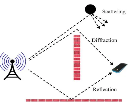
2.1 An example of reflection, diffraction and scattering components . . 30 2.2 An example of AtG channel . . . 31 2.3 An example of user points following HPP withλs=200 . . . 36 2.4 An example of user points following IPP withλ(x,y) =300(x2+
y2) . . . 37 2.5 An example of user points following PCP withλp=10 . . . 38
3.1 System model . . . 41 3.2 Converting the non-convex region into convex regions with
geomet-rical relaxation . . . 45 3.3 An example of feasible region definition, with two deployed aerial
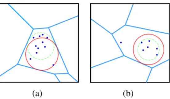
BSs, for the positioning of the third BS . . . 47 3.4 The case for optimizing the radius inK-means circle placement
al-gorithm: (a) flexibility in reaching additional users, (b) reducing power for a given user coverage area. . . 54 3.5 An example deployment of SD-KMVR in the existence of
imper-fect ULI, with dots representing estimated user locations and small circles in red representing real user locations. . . 57 3.6 Computational complexity: (a) average execution time of solving a
single MINLP problem by MOSEK solver,K=1; (b) CDF of num-ber of iterations required for K-means clustering and SD-KMVR,
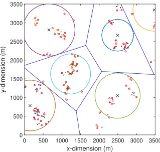
K=9,λs=10 users/km2 . . . 60 3.7 Aerial BS placement with proposed techniques . . . 65
List of Figures 15 3.8 User-coverage probability for different types of user distribution:
(a) with perfect ULI, (b) with imperfect ULI, (c) with robust tech-nique,K=4 . . . 66 3.9 User-coverage probability versus number of UAVs deployed,K=16,
15 and 10 for HPP, IPP and PCP correspondingly . . . 68 3.10 Coverage probability with additional constraint specifying the
max-imum number of served user. Ls=4R. . . 69 3.11 Required number of aerial BSs and total transmit power versus size
of target area . . . 70 3.12 Average execution time for the proposed techniques: (a) versus
var-ious user density, K = 9 (b) versus various number of aerial BSs, λs=5 users/km2 . . . 71 4.1 Aerial BS serving delay-tolerant users . . . 74 4.2 An example of CIT, DIT and the generated trajectory after one
iter-ation of Algorithm 4 with DIT,T =100s,Etot=1.5×10⁴J . . . 85 4.3 Optimizing the trajectory with respect to the worst case ULI . . . . 87 4.4 Optimized trajectory with IA-CIT,T=100 s,Etot=1.5×10⁴J . . . 91
4.5 Speed of aerial BS corresponding to the trajectory shown in Fig. 4.4 91 4.6 Optimized trajectory with IA-CIT for different time periodT,Etot=
2.5×10⁴J . . . 93 4.7 Optimized trajectory with IA-CIT for different on-board energy
Etot,T=120 s . . . 93 4.8 Coverage probability versus time period T with different
tech-niques,Etot=2.5×10⁴J . . . 94 4.9 CDF of number of required iterations for IA-CIT and IA-DIT,
Etot=2.5×10⁴J,T=120 s . . . 95
4.10 Average energy consumption for IA-CIT and IA-DIT,Etot =2.5× 10⁴J . . . 96 4.11 Coverage probability with imperfect ULI and Robust techniques,
List of Figures 16 4.12 Coverage performance of Robust techniques versus various
List of Tables 17
List of Tables
1.1 Potential UAV-enabled communication applications . . . 21
1.2 Research directions and challenges . . . 25
3.1 Computational Complexity of the Proposed Techniques . . . 64
3.2 Simulation parameters1 . . . 65
18
Chapter 1
Introduction
1.1
Background and Literature Review
1.1.1
Potential Use Cases of UAV-enabled wireless networks
To satisfy the incessantly increasing and highly diversified data demand for the upcoming fifth-generation (5G) mobile communication system, researchers have devoted significant efforts to exploring new wireless technologies, such as mas-sive multiple-input multiple-output (M-MIMO), millimeter wave (mmWave) and device-to-device (D2D) communication [1–4]. Despite the significant benefits, all these technologies were mainly designed for terrestrial communication systems with fixed ground base stations (BSs) and have their own drawbacks and limita-tions.
Recently, there have been increased interests in providing wireless communi-cation services from the sky. One solution is using high-altitude platforms (HAPs), such as airships and balloons [5, 6]. Since HAPs are usually operate at a high alti-tude which is tens of kilometers above the ground, such platforms can offer wide coverage area and usually have long endurance [7]. On the other hand, unmanned aerial vehicle (UAV) based low-altitude platforms (LAPs) have several advantages compared to the terrestrial communication and HAP based communication. For instance, UAVs are more swift, flexible and cost-effective [8]. In addition, drones are usually deployed at an altitude of several hundred meters, so there is a large probability of short-range line-of-sight (LoS) air-to-ground (AtG) communication
1.1. Background and Literature Review 19 channel. Undoubtedly, thanks to the advantages mentioned above, UAVs are re-garded as an inevitable complement in future communication systems, which will bring unique benefits of its own and enable to address some problems of existing technologies.
It is known that D2D networks enable direct communication between mobile devices without going through BSs, and thus improve the performance regarding spectral efficiency and access delay [9, 10]. However, reliable and efficient commu-nication performance can only be achieved within short commucommu-nication range and direct communication among various access points may cause severe interference issues. Use of UAV is a potential way to overcome the challenges in D2D net-works [11–13]. The main advantage of UAV-assisted D2D netnet-works is that the use of UAVs greatly reduces the number of required transmission links among ground devices, thus mitigates the interference in the D2D networks. Besides, due to the flexibility and maneuverability, UAVs can disseminate emergency information to a large number of devices, which is relevant in public safety situations [11].
Catering for reliable communication and high data rate, the 5G cellular paradigm tries to exploit the underutilized millimeter-wave (mmWave) spec-trum [2, 14, 15]. However, the mmWave links also lead to high path loss and are susceptible to obstacles along the communication path. UAVs which fly in the air and enjoy LoS AtG communication condition is an ideal enabler for mmWave communication [15–18]. On one hand, with UAVs as enablers, the communication link can be hardly blocked and the path loss is greatly reduced. On the other hand, equipped with multiple small size antennas, UAVs can realize the more advanced massive MIMO techniques from the sky.
In addition, use of UAVs is promising in the Internet of Things (IoT) networks which have a strict requirement on energy efficiency and reliability. In general, IoT devices are highly battery-limited and have a short communication range [19–22]. In addition, since IoT devices have various applications, they might be deployed in places where there is a poor coverage or even no coverage of terrestrial cellular net-works [13, 22]. The above challenges can be efficiently solved with UAVs serving
1.1. Background and Literature Review 20 as aerial base stations (BSs). First, due to the flexibility of UAV, aerial BSs can be deployed based on the location of IoT devices and the devices are only associated with UAV when there is a good enough communication condition. In this way, the IoT devices can transmit information with a clearly reduced transmit power and the life time of the IoT network is greatly increased correspondingly [19, 20, 22–24]. Second, aerial BSs can be deployed in areas with no ground communication infras-tructures such as mountains to enable the function of IoT devices.
In fact, UAV based aerial BSs can provide fast and reliable wireless services wherever and whenever there is an excessive data requirement and is another main application of UAV. While ultra dense small cell networks are envisioned as an important part in 5G communication system to further improve the throughput, deploying such networks is challenging in geographically constrained areas [25]. Meanwhile, terrestrial communication infrastructures can be severely damaged or even completely destroyed during natural disasters such as hurricane and earth-quake. Aerial BSs, on the other hand, can fly to any places and are able to provide fast service recovery in emergency or disaster scenarios [11, 26, 27]. Moreover, aerial BSs can also ease the burden of terrestrial base stations in extremely crowded areas by offloading a part of users from ground cells [28]. This is especially useful in the cases of temporary events such as Olympic games where it is not cost effec-tive to deploy multiple small ground cells.
Another promising use of UAV is relaying [29, 30]. Currently, most relays are deployed in fixed locations due to constraints like wired backhaul and limited mobility. This limits the use of relay in more specific scenarios such as battlefield. When UAV is used for mobile relaying, it extends the coverage and increases the throughput from the source node to the destination node by dynamically flying closer to the node which has a communication demand [23, 31–34].
Besides all the use cases mentioned above, wireless power transfer (WPT) is also an application which benefits from the mobility of the UAV. In conventional WPT systems, energy transmitters are deployed at fixed locations to charge the energy receivers. Therefore, for addressing the low power transmission efficiency
1.1. Background and Literature Review 21
Table 1.1: Potential UAV-enabled communication applications Use Cases Drawback of Existing
Technology
Main Advantage of us-ing UAV Key References D2D net-works • Interference among mobile devices • short communication range • Mitigate interference issue • Improve connectivity • Broadcast emergency information [11–13, 35] Enabler for mmWave • Bad performance in multi-path fading envi-ronment
• High path loss
• Bring LoS communi-cation condition [15–18, 36] IoT net-works • Battery-limited IoT devices • Short communication distance • Bad performance in geographically con-strained areas • Improve endurance of IoT networks • improve communica-tion condicommunica-tion
• Enable IoT devices in geographically con-strained areas [19, 20, 22– 24] Aerial BSs • Expensive terrestrial infrastructures • Susceptible to natural disasters • Cost effective • Service recovery in emergency or disaster scenarios
• Ease the burden of ground cells
[11, 26–28, 37, 38]
Relaying • Fixed locations and limited performance
• Improve communica-tion performance
• Wide application sce-nario
[23, 31–34]
WPT • Low power transmis-sion efficiency
• Expensive infrastruc-tures
• Increase transmission efficiency with lower cost
[39, 40]
due to the long communication distance, the energy transmitters need to be placed in an extremely dense manner which increases the cost [39]. UAV-enabled WPT can greatly increase the energy transferred to all energy receivers by flying close to the targets and reduce the energy loss [40].
For brevity, we summarize all the potential use cases of UAV in Table 1.1. Note that, in this paper, we restrict our attention to UAV-aided aerial BSs, which might be the most imminent application. In the following section, we review the
1.1. Background and Literature Review 22 state-of-the-art and show the main research directions as well as the challenges regarding deploying aerial BSs.
1.1.2
Research Direction and Challenges of aerial BSs
With the rising interest in deploying aerial BSs to achieve better communication performance, the challenges in the practical use of aerial BSs are becoming perti-nent.
1.1.2.1
AtG Channel Modeling
The first research topic that plays an important role in the real application of aerial BSs is the accurate modelling of AtG communication channel. Although AtG communication links are dominated by LoS links in general, they can be occasion-ally blocked by obstacles such as buildings and terrains [11]. The probability of NLoS links becomes non-negligible in highrise urban environments [26]. While ray-tracing technique is widely utilized for approximating the AtG channels, it still lacks accuracy [41].
Recently, the AtG modelling problem has been extensively studied in the literature. For example, authors in [42] gave an model of AtG channel while con-sidering the possible effects of small-scale fadings. The work [43] verified that AtG links experience less shadowing and path loss than the channels in terrestrial com-munication systems. An elevation dependent shadowing model is then presented in [44]. It is worth highlighting that [26] gives a simplified model of AtG channel by considering the probability of both LoS and NLoS links.
1.1.2.2
Deployment of Static Aerial BSs
Since aerial BSs can hold stationary in the air, providing coverage to ground users, the priority of static aerial BSs is finding the optimal locations of UAVs so that a maximum number of ground users can be covered. This is relevant in emergency scenarios such as search-and-rescue after natural disasters and rural area scenarios where there is no ground infrastructures. The optimal three dimensional placement
1.1. Background and Literature Review 23 of UAVs is challenging as it is affected by a large number of factors such as UAV’s altitude, AtG channel characteristics, locations of ground users and specific deploy-ment environdeploy-ment. When more than one aerial BS is deployed, the effect of ICI should also be considered, which further challenges the successful deployment of UAVs [45, 46].
The aerial BS coverage problem was first studied in [26], which gave an AtG channel model used to find the optimal altitude of UAVs that can lead to maximum coverage area on the ground. Moreover, recent research focus has shifted from maximizing the coverage area towards covering a maximum number of ground users [27, 28, 37, 47]. Specifically, [47] formulated a 3-D circle placement problem as a MINLP and solved the problem with convex optimization techniques. In [28], the authors did an exhaustive search in girds to obtain the optimal location of an aerial BS. However, all the works mentioned above considered only the case of a single static aerial BS which limits their use. Unlike HAPs such as balloon and airships, UAV which is a typical LAP has a limited coverage area of around several square kilometers. In practice, it is usually a necessity to deploy multiple UAVs simultaneously so a majority of ground users in a specific target region can be covered. Mozaffariet al. [45] first extended the number of used aerial BSs to two with a careful consideration of ICI. Then the same group [48] proposed a circle packing theory (CPT) so that the total coverage area of multiple aerial BSs is maxi-mized. However, the work did not consider the effect of different user distributions. In [49], a 100% user coverage probability is achieved through a spiral algorithm, however, the study ignores the effect of ICI which needs to be tackled with overlaid techniques.
1.1.2.3
Trajectory Design of Moving Aerial BSs
The potential of aerial BSs can be fully exploited by leveraging the mobility of UAVs. Correspondingly, trajectory design of UAVs might be the main challenge involved in UAV-based aerial BSs. In general, the trajectory design of UAV requires jointly considering the constraints with regard to flying status, flight time, collision
1.1. Background and Literature Review 24 avoidance, scheduling and user demand [11]. Moreover, for solving a continuous UAV trajectory optimization problem, one needs to tackle with an infinite number of optimization variables. All these factors make the trajectory design of aerial BSs challenging.
Significant efforts have been devoted to solving the trajectory optimization problem [20,50–53]. By assuming the users are distributed along a one-dimensional line, a novel cyclical multiple access (CMA) method was proposed for moving aerial BSs in [51]. Authors in [20] jointly optimize the UAV trajectory and user scheduling variables to increase the maximum throughput gain. In addition, the works in [54] studied the path planning for localization purposes. [53] offloads the data traffic of cell edge users by letting a moving aerial BS fly cyclically around a ground BS. In [55], the optimal trajectory of a UAV deployed with multiple anten-nas was investigated for the aim of sum-rate maximization.
1.1.2.4
Energy Efficiency
Last but not the least, since UAVs use built-in batteries for supplying power in most cases, limited on-board energy is a key factor that constrains the performance and endurance of aerial BSs [11, 56–58]. Both communication functions and moving properties consume the built-in energy. In general, the expression of the propulsion power which is a function of the flying status of UAV is hard to be derived and is normally non-convex.
For static aerial BSs where the UAVs remain stationary in the sky, it has been proven that prolonged operation time can be achieved by reducing the transmit power as long as the quality-of-service (QoS) requirements are satisfied [47, 59]. For moving aerial BSs, however, the consumed propulsion energy is much larger than the communication-related energy. Therefore, trajectory design takes an im-portant part in energy efficient communication when mobility of the UAV is ex-ploited. Without considering the propulsion energy for supporting the movement of UAVs, efficient usage of energy for communication related functions have been studied in [60–62]. Authors in [24] took the propulsion power consumption into
1.1. Background and Literature Review 25
Table 1.2: Research directions and challenges Research Directions Challenges Representative Techniques Key References AtG channel modeling • Various environment • Path loss • Small-scale fadings • Extensive measure-ments
• Ray Tracing technqi-ues [26, 42– 44] Deployment of static aerial BSs • 3-D deployment • ICI
• Energy efficient de-ployment
• Circle packing Theory (CPT) • Machine Learning algorithms • Spiral Algorithm [26–28, 37, 47–49] Trajectory design of moving aerial BSs • Massive coupled constraints • Energy-aware trajectory
• Infinite number of op-timization variables • Convex optimization • Machine learning algorithms • Discretization methods [20, 50– 53, 55] Energy efficiency • Power consumption model • Energy-performance Tradeoff • Convex optimization • Machine learning algorithms [24, 47, 59–63]
consideration and gave a model of consumed propulsion power of fixed wing UAVs. Moreover, authors in [63] minimize the total power consumption of a UAV with a guaranteed transmission rate.
For simplicity, we summarise the main research directions as well as the challenges in these areas in Table 1.2. In this thesis, we focus on the coverage per-formance and endurance of aerial BSs. Both the optimal deployment of static aerial BSs and the optimal trajectory of moving aerial BSs are studied. To be specific, when multiple static aerial BSs are deployed, we try to maximize the number of covered ground users while avoiding the effect of inter-cell interference (ICI). In addition, when moving aerial BS is considered, we try to satisfy the data demand of a maximum number of ground users by optimizing the trajectory and UAV-user scheduling with a given energy budget, which is the bottom line aim of UAV appli-cation. The detailed contributions can be found in the following section.
1.2. Contributions 26
1.2
Contributions
In this thesis, we study the coverage performance of both static aerial BS and mov-ing aerial BS. Regardmov-ing static aerial BS, we consider a scenario that multiple aerial BSs are deployed simultaneously to cover a maximum number of ground users while avoiding ICI. Therefore, it is of great interest to study the optimal location of aerial BSs. Since the endurance of aerial BSs is limited by the on-board energy, we minimize the transmission power to prolong the battery life of UAVs. Regarding moving aerial BS, we consider a scenario that an aerial BS is dispatched to meet the data demand of a maximum number of ground users before exhausting its limited on-board energy and flying back to the base for charging. It is mentionable that per-fect user location information (ULI) may not available in practice, so we propose various robust techniques for compensating the performance loss in the existence of inaccurate ULI. The main contributions of this thesis are summarized as follows:
• UAV Positioning Optimization (Chapter 3): With regard to the static aerial BS scenario, we first propose a successive deployment scheme, in which the next aerial BS is always deployed in a position such that a maximum number of remaining users in the target area can be covered. The resulting optimization problem involves a increased number of non-convex constraints which are tackled with a simple geometrical relaxation method. After that, a more effi-cient technique which deploys all the aerial BSs simultaneously is proposed with the help ofK-means clustering. In the simultaneous deployment method, the whole target area is divided into multiple polygon regions where convex optimization problems can be solved. Furthermore, an iterative algorithm is further proposed to improve the coverage performance while reducing the re-quired transmit power consumption. Finally, a robust technique is proposed to maximize the number of covered users in the existence of imperfect ULI and the computational complexity of all the proposed techniques are derived analytically.
• UAV Trajectory Optimization (Chapter 4): By fully exploiting the mobil-ity of UAV, we try to satisfy the data requirement of a maximum number
1.3. List of Publications 27 of ground users while considering constraints on energy resources. The for-mulated mixed integer non-linear problem (MINLP) is solved by an efficient iterative algorithm where successive convex optimization and block coordi-nate descent techniques are applied. Next, since the convergence speed and achievable performance of such iterative algorithm depends on the adopted initial trajectory, we design an initial trajectory which gives all users a rela-tively fair chance to be scheduled and associated. In addition, the existence of inaccurate ULI is also considered, and we propose two different robust techniques to compensate the loss in coverage performance. Specifically, the first robust technique optimizes the worst case coverage performance and the second robust technique maximizes the minimum excess data for the covered ground users.
Based on the above contributions, we have produced academic papers for publica-tion which are listed below.
1.3
List of Publications
1.3.1
Accepted Papers
1. J. Sun and C. Masouros, ”Deployment Strategies of Multiple Aerial BSs for User Coverage and Power Efficiency Maximization,” IEEE Transactions on Communi-cations, Early Access, URL: https://ieeexplore.ieee.org/document/8587183
2. J. Sun and C. Masouros, ”Drone Positioning for User Coverage Maximization,”
2018 IEEE 29th Annual International Symposium on Personal, Indoor and Mobile Radio Communications (PIMRC), Bologna, 2018, pp. 318-322.
1.3.2
Papers Under Review
1. J. Sun and C. Masouros, ”Energy Aware Trajectory Optimization for Aerial Base Stations,” IEEE Transactions on Communications, under review, submitted 21/01/2019.
1.4. Thesis Organization 28
1.4
Thesis Organization
The rest of the thesis is organized as follows. In Chapter 2, we introduce the AtG channel model and the fundamental knowledge of multiple access techniques, fol-lowed by the description of spatial point process methods which are used to model the user distribution. In Chapter 3, we study the coverage performance of mul-tiple static aerial BSs. After introducing the system model, we first propose one successive deployment technique and two simultaneous deployment techniques to optimize the location of aerial BSs to cover a maximum number of ground users while avoiding the effect of ICI. A robust technique designed for inaccurate ULI and the computational complexity analysis are shown afterwards. In Chapter 4, we first propose an iterative algorithm which optimizes both the trajectory and UAV-user scheduling to meet the data demand of a maximum number of ground UAV-users before exhausting the UAV’s on-board energy. Next, we show a designed initial tra-jectory which speeds up the convergence and improves the coverage performance. Two different robust techniques which compensate the performance loss in the ex-istence of imperfect ULI are then studied in this chapter. Finally, in Chapter 5, we conclude the whole thesis.
29
Chapter 2
Air to Ground (AtG) communication
system
2.1
Introduction
In this chapter, we introduce fundamental concepts which are highly related to the AtG communication. We begin with an overview of communication path loss model and indicate the main channel characteristics of AtG communication system. The commonly used performance metrics are also introduced. Next, the main types of multiple access techniques are described followed with the introduction of a new multiple access technique called cyclical time-division multiple access (CTDMA) which is tailored for moving aerial BSs. Since we aim at covering a maximum num-ber of ground users and user distribution exerts a significant effect on the coverage performance, we finally introduce the techniques that are used for modeling the user distribution.
2.2
Path Loss Model
The wireless channel places fundamental limitations on the performance of AtG communication system. Same as terrestrial communication system, the perfor-mance of AtG communication is limited by the variations in signal strength due to fading effects. Generally, the fading effects can be classified into two main types, which are scale fading effect and small-scale fading effect [64]. The large-scale fading characterizes the mean received signal strength and tells us how much
2.2. Path Loss Model 30
Figure 2.1:An example of reflection, diffraction and scattering components
a signal is going to attenuate over the channel. Small-scale fading effect, on the other hand, characterizes the rapid fluctuations in received signal strength and is a result of multi-path fading.
As depicted in Fig. 2.1, reflection, diffraction and scattering are the main con-tributors of multi-path fading effect. The received signal through multi-path chan-nel is thus an addition of multi-path components of the transmitted signal and these components can be either constructive or destructive [65]. When different copies of the transmitted signal add destructively, the signal level declines which increases the detection difficulty. Since there are obstacles between the transmitter and the re-ceiver, and the signal is not propagated along a straight line, the paths shown in Fig. 2.1 are all non-line of sight (NLoS) paths. In AtG communication system, how-ever, there is a large probability that there is no obstruction between the transmitter and the receiver, and the communication channel is dominated by short-length LoS path [66]. In the case of LoS link, we have negligible small-scale fadings and the channel quality depends only on the distance between the transmitter and receiver, which follows free-space path loss (FSPL) model given by
PL=20log 4πfcd c (2.1)
2.2. Path Loss Model 31
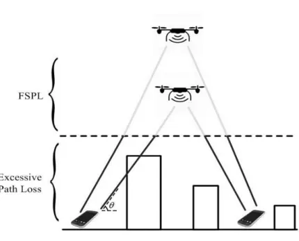
Figure 2.2:An example of AtG channel
where fc denotes the carrier frequency and d denotes the distance between trans-mitter and receiver. Although LoS links are expected for AtG communication chan-nels, the channel can be occasionally blocked by obstacles such as buildings in practice [11]. Therefore, following [26], we can describe the probability of LoS link as
Pr(LoS) =
1
1+aexp(−b[θ−a]) (2.2)
whereaandbare parameters related to the specific environment andθ denotes the elevation angle as shown in Fig. 2.2. In dense urban where there is a high density of buildings with high altitude, we have largeaandbparameters and thus a small probability of LoS links. In suburban areas, however, buildings are placed sparsely and the communication link can hardly be blocked. In addition, the probability of LoS can be increased by deploying UAVs in a higher altitude. Sinceθ =arctan(HR), with H denotes the altitude of the UAV and R denotes the coverage radius, the elevation angle hence the probability of LoS link can be increased by increasing the altitude of UAV with a fixed radius. This is also verified in Fig. 2.2.
When the AtG channel is blocked by obstacles, the communication suffers additional excessive path loss which is a result of multi-path fading effects. The
2.3. Performance Metrics 32 NLoS communication channel is thus expressed as
PLNLoS=20log 4πfcd c +ηNLoS (2.3)
where ηNLoS denotes the excessive path loss. For simplicity, we assume that the
AtG communication channel is dominated by the LoS links in this thesis.
2.3
Performance Metrics
In this section, performance metrics that are commonly used to evaluate the perfor-mance of aerial BS is introduced. We start with the concept of received power and signal-to-noise ratio (SNR) which are two metrics used for determining the cover-age area of static aerial BS. Then definition of achievable data bits and covercover-age probability is given.
2.3.1
Static Aerial BS
When a static aerial BS is deployed, we usually want to maximize the coverage area which is defined as the expected percentage of locations where the received power at these locations is above a certain threshold [65]. All covered ground users require some minimum SNR for maintaining an acceptable communication performance, where SNR is defined as the ratio of received power to the noise power as follows.
SNR=Pr
σ2 (2.4)
whereσ2 denotes the noise power. Assuming we have a fixed level of noise, the SNR requirement translates to the received power requirement. In other word, all covered users should have a received power larger than a given minimumPmin. If we denote the transmit power of aerial BS asPt and denote the antenna gain asG, the received power in dB is given by
2.3. Performance Metrics 33 Since AtG communication channel is dominated by LoS links as mentioned in the above section, we ignore small-scale fluctuations and the received power threshold
Pminindicates a circular coverage area of the aerial BS.
In some specific areas, the signals are frequently blocked and we must consider the shadowing effects. In this case, some locations within the coverage area have received power belowPmin and it is impossible for all users located at the coverage boundary to receive same power level [65]. We assume the excessive path loss follows ηNLoS ∼N(µNLoS,σNLoS2 ), where µNLoS and σNLoS2 denote the mean and
variance of shadow fading respectively. Therefore, for a ground user which located at a distance r≤ tanH
θ from the position of UAV in the horizontal dimension, its
coverage probability is given by [48]
Pcov=Q Pmin+PL−Pt−G+µNLoS σNLoS (2.6)
whereQ(.)is Q-function described as
Q(z) = Z ∞ z 1 √ 2π e−x 2 2 dx (2.7)
Correspondingly, the outage probability is defined asPout=1−Pcov.
In this thesis, the most important performance metric is coverage probability. When static aerial BS is deployed, coverage probability is defined as the ratio of number of covered ground users to the total number of ground users in a specific target area.
2.3.2
Moving Aerial BS
When the mobility of UAV is exploited, the aerial BS usually associates the ground users in a cyclical time-division manner and an important performance metric is the achievable data of the ground users. We assume the aerial BS uses a total ofN
time slots to communicate with the ground users, and we define a binary variable α[n]indicating the scheduling and association status of a ground user in time slotn, wheren=1,2, ...,N. To be specific,α[n] =1 indicates that the user is allocated for communicating with the aerial BS at time slotn, α[n] =0 otherwise. If we denote
2.4. Multiple Access Techniques 34 the SNR in time slotnasγ[n], the total achievable data is
R=
N
∑
n=1
α[n]Blog2(1+γ[n]) (2.8)
where B is the total available bandwidth. Sometimes we focus on the achievable average data rate, which can be obtained by averaging the total achievable data over the whole time period and is thusR= N1R.
When moving aerial BS is deployed, we have a different definition for the covered users and thus a different concept of coverage probability. In this case, a user is covered only when his data demand is fully satisfied. Correspondingly, the coverage probability is defined as the ratio of number of satisfied users to the total number of ground users.
2.4
Multiple Access Techniques
In this section, we introduce the multiple access techniques which are commonly used for UAV-enabled communication systems. We start from frequency division multiple access (FDMA) and time division multiple access (TDMA) which are con-ceptually easy to understand. Then we introduce a new TDMA technique called cyclical time division multiple access (CTDMA) that is designed specifically for moving aerial BSs. In addition, more advanced multiple access techniques such as code division multiple access (CDMA) and space division multiple access (SDMA) are also introduced.
2.4.1
FDMA
Although FDMA might be the oldest multiple access technique which has been used since advanced mobile phone system (AMPS), it still has its usage today and may take an important part in UAV-enabled communication systems. When static aerial BS is deployed, FDMA is the most commonly used multiple access technique in the literature. The core idea of FDMA is that each user is allocated a separate frequency band for transmission during the whole time period. It requires little digital signal processing and has simple temporal synchronization [67]. Unfortunately, FDMA
2.4. Multiple Access Techniques 35 wastes spectrum and frequency resources
2.4.2
TDMA
In TDMA, a time unit is divided into multiple time slots of fixed length, and each user is assigned one of such time slots [67]. Unlike FDMA, during each time slot, the whole bandwidth is reserved for exclusive use so the user can transmit with higher data rate. Note that TDMA is widely used for moving aerial BSs where the aerial BS only allocates time slots to a ground user when it flies sufficiently close to the user and enjoys the good communication condition. In some scenarios, the UAV is dispatched periodically to serve the ground users, and within each period the ground users are scheduled and associated with TDMA. Such multiple access technique which periodically serves the ground user is also known as CTDMA as proposed in [51].
2.4.3
CDMA
Compared to FDMA and TDMA, CDMA is a more advanced multiple access tech-nique and could be used by aerial BSs. CDMA uses the technology of spread spec-trum (SS), where the transmitted specspec-trum is spread by multiplying the signal with chip sequence [67]. Since the generated chip sequence appears as random noise, the sequence is also known as pseudo-noise (PN) sequence. In CDMA, a unique PN sequence is assigned to each user and the cross-correlation of any two codes are zero, so there is no interference between users [67]. In this case, all active users transmit information simultaneously over the same bandwidth without interfering with each other. At the receiver, correct information can be extracted only when the same PN sequence as used in the transmitter is applied.
2.4.4
SDMA
Due to limited payload and size of UAV, the aerial BSs are usually deployed with single antenna. It is envisioned that multiple antennas may be deployed in aerial BSs to increase the throughput. SDMA is a multiple access technique for systems with multiple antennas. In this method, multiple users can be served simultaneously with the same frequency, because the BS distinguishes different users by means of
2.5. User Distribution 36 x-dimension (m) 0 200 400 600 800 1000 y-dimension (m) 0 200 400 600 800 1000
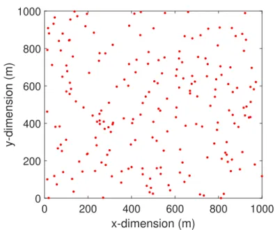
Figure 2.3:An example of user points following HPP withλs=200
various spatial characteristics. [67].
2.5
User Distribution
In this paper, aerial BSs are deployed to cover a maximum number of ground users. In order to capture a random pattern of ground users in the target area, we use a statistical model called spatial point process (SPP). We assume three types of SPPs, namely homogeneous Poisson process (HPP), inhomogeneous Poisson pro-cess (IPP) and Poisson cluster propro-cess (PCP) [68, 69]. A majority of user distribu-tions in real scenarios can be described accurately with the help of these three SPP models. LetDdenote a bounded set,X(D)denote a counting measure ofDwhich calculates the random number of points inD, and µ(D)is a mean measure of D, giving the expected number of points.
2.5.1
Homogeneous Poisson process (HPP)
When HPP is applied, all user points are uniformly and independently distributed within the target areaW. We denote the point density which describes the average number of user points in a unit area asλs. Therefore, we have constantλs in HPP
2.5. User Distribution 37 x-dimension (m) 0 200 400 600 800 1000 y-dimension (m) 0 200 400 600 800 1000
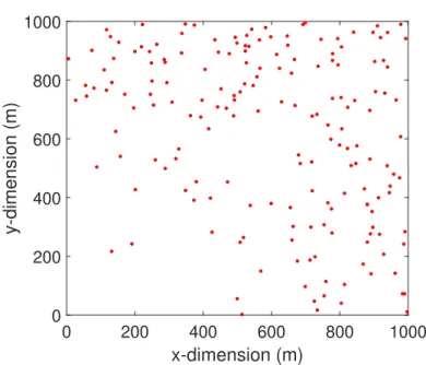
Figure 2.4:An example of user points following IPP withλ(x,y) =300(x2+y2)
and any user(xi,yi)generated with HPP follows
P((xi,yi)∈S) =
S
W (2.9)
for any subarea S of the target areaW. Note that the number of generated user points follows Poisson distribution, which isX(D)∼Poisson(λs·W). The expected number of points is given byµ(D) =λs·W. An example of user points distributed following HPP is shown in Fig. 2.3.
2.5.2
Inhomogeneous Poisson process (IPP)
In some cases, grounds users are distributed unevenly, with users in some areas lo-cated more densely than other areas. Correspondingly, we need a more general SPP model which introduces inhomogeneity. When IPP is applied, the constant point densityλs is replaced by an intensity functionλ(x,y), which varies with locations in the target area. Correspondingly, we have
µ(D) =E{X(D)}=
Z
D
2.5. User Distribution 38 x-dimension (m) 0 200 400 600 800 1000 y-dimension (m) 0 200 400 600 800 1000
Figure 2.5:An example of user points following PCP withλp=10
where E{.} is the expectation operator. The corresponding number of generated user points is thusX(D)∼Poisson(µ(D)), withµ(D)obtained from (2.10). Note that various intensity function leads to various patterns of ground users. Fig. 2.4 shows an example of ground users generated with
λ(x,y) =300(x2+y2) (2.11)
It can be seen that, with such a density function, less users are located in the left bottom corner.
2.5.3
Poisson cluster process (PCP)
In practice, ground users often gather around points of interest such as concert and stadium, in which case their distributions involves clustering. In order to describe this kind of user distribution, PCP is utilized [69]. For applying PCP, a set ofparent
pointsSpis first generated following HPP with constant point densityλp. Then for eachc∈Sp, childrenpoints which are also known as offspringpoints are indepen-dently generated following Poisson process with intensity functionλc(x,y). In this case, childrenpoints are distributed in circles around corresponding parent points to form clusters. Fig. 2.5 shows an example of generated user points withλp=10
2.5. User Distribution 39 users/km2and thechildrenpoints generated with
λc(x,y) = α 2π σ2e − 1 2σ2(x 2+y2) (2.12)
where α =0.9 and σ =0.02. Note that for all the SPPs, Simplicity property is satisfied, which means the generated points never coincide [69].
40
Chapter 3
UAVs Serving as Static Aerial BSs
3.1
Introduction
As mentioned in Chapter 1, the priority of static aerial BSs is finding the opti-mal locations of UAVs so that the aerial BSs can cover a maximum number of ground users. This is relevant in emergency scenarios such as search-and-rescue after natural disasters and rural area scenarios where there is no ground infrastruc-tures. Meanwhile, since UAVs usually use built-in batteries for supplying power, limited on-board energy is another key factor that limits the lifetime of aerial BSs [11, 56–58].
In this chapter, we study the efficient deployment of multiple UAVs so the maximum user coverage probability is achieved while avoiding the effect of ICI. Following [48, 49], we assume that the UAVs have the knowledge of ULI with the help of high-accuracy GPS systems and each aerial BS has enough capacity to supply all the users within its coverage area. We further assume that the ground users have low mobility. We consider a practical scenario where multiple aerial BSs are deployed in a target area without the service of ground BSs. Note that this is relevant in rural area coverage in cases where terrestrial BSs are absent, and in nat-ural disaster scenarios where terrestrial infrastructures are damaged. Rotary-wing UAVs are chosen as the carrier for static aerial BSs since they have the ability to hold still in the air as well as move in arbitrary directions [11]. The UAV place-ment problem is modelled as a circle placeplace-ment problem and the ICI is avoided
3.2. System Model 41
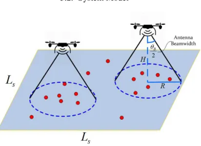
Figure 3.1:System model
by allowing no coverage overlap. Three different deployment methods are pro-posed successively, and our simulation results demonstrate that the propro-posed circle placement methods achieve better user coverage performance than the benchmark technique. Furthermore, when the simultaneous deployment methods are applied, the increased coverage probability is achieved with significantly reduced transmit power in certain scenarios. We finally consider the existence of inaccurate ULI and propose a robust technique to compensate the performance loss.
3.2
System Model
We consider a square geographical target area with side lengthLs containing a set of low-mobility users denoted byM as shown in Fig. 3.1. We assume a total ofK
aerial BSs are deployed within the region in order to provide wireless coverage to as many ground users as possible. Note that, due to the mobility of UAVs, such de-ployment of aerial BSs can be done regularly in order to accommodate any changes in the user positions. Since static aerial BSs are considered, we will only focus on each snapshot of users within the area instead of studying the trajectory of UAVs. We assume that each aerial BS is equipped with a single directional antenna, and the half-power beamwidth of the antenna is denoted asθB. Following the work [29,48],
3.2. System Model 42 the antenna gain can be approximated by
G= G0,−θ2B≤φ≤ θB 2, g(φ),otherwise, (3.1) where G0 ≈ 29000
θB2 is the main lobe gain of the directional antenna. For sim-plicity, we assume the power gain outside of the main lobe is negligible, that is
g(φ) ≈0. We denote the location of user i in the set M as (xi,yi), the hori-zontal location and the altitude of the k-th UAV as (xck,yck)and hk, k=1,2, ...K
respectively. Therefore, the ground distance between the i-th user and the k-th UAV is lik=
q
(xi−xck)2+ (yi−yck)2. In addition, the coverage area of thek-th aerial BS can be approximated as a circle region centered at(xck,yck), with radius
Rk=hktanθB 2
, and thei-th user is covered by thek-th aerial BS whenlik≤Rk. For ease of exposition, and following [24, 49, 53], we assume that the AtG communication channels are dominated by LoS links. In fact, recent field exper-iments carried out by Qualcomm have verified that the AtG channels are indeed dominated by the LoS links [70] and the high probability of LoS links is one of the main reasons that motivates us to deploy aerial BSs. Under the LoS models, we have negligible small-scale fadings, and the channel quality depends only on the distance between UAVs and users, which follows FSPL model given by
PLik=20 log 4πfcdik c (3.2)
wherecdenotes the light speed and fc denotes the carrier frequency of the system. Additionally,dikrepresents the Euclidean distance between useriand thek-th aerial BS, which is given by
dik=
q
lik2+hk2 (3.3)
As mentioned in the previous chapter, the service threshold of a BS is defined in terms of the received power. We denote the received power of useri asPri. If the transmit power of thek-th aerial BS is denoted byPtk,Priin dB is given by
3.3. Proposed Deployment Methods 43 It can be seen from (3.4) that the users located on the border of the circle coverage area will suffer more severe path loss than other covered users. More importantly, the received power of any user who is covered by the aerial BS should be larger than or equal to the threshold valuePmin. Therefore, aerial BSs which are deployed at a higher altitude require an increased transmit power. Note that when multiple aerial BSs are deployed, the effect of ICI needs to be addressed. With the use of directional antennas and following the LoS channel model, it can be found that the interference effect can be intrinsically avoided when there is no overlap between coverage areas of aerial BSs.
3.3
Proposed Deployment Methods
In this section, we introduce the proposed deployment methods for achieving the best coverage performance based on the system model introduced above. The first proposed technique deploys the UAVs in a successive way while the other two tech-niques simultaneously deploy all the aerial BSs with the help ofK-means clustering. Note that, the third technique can be regarded as a advanced method of the second technique, which further improves the coverage probability while increasing the endurance of aerial BSs.
3.3.1
Successive Deployment Method with Geometrical
Relax-ation (SD-GR)
We first propose a method based on successive circle placement to find the optimal locations of aerial BSs such that a maximum number of ground users can be cov-ered. Following [48], and as shown in Fig. 3.1, we assume that all UAVs have the same antenna beamwidthθB and are flying at a fixed altitudeH. Correspondingly, all the aerial BSs have the same coverage radiusR, that is
hk=H,k=1,2, ...,K (3.5)
Rk=R,k=1,2, ...,K R=Htan(θB
3.3. Proposed Deployment Methods 44 Therefore, deploying multiple aerial BSs is equivalent to placing multiple circles in the horizontal plane such that the number of enclosed user points is maximized. UAVs are placed in a successive method, where at each step the placement of the aerial BS aims to cover the maximum number of remaining users in the target area while ensuring that there is no overlap in coverage areas with all previously de-ployed BSs. The first aerial BS can be placed with the method proposed in [47]. We denote the coverage area of the first UAV asC1 and define an integer variable
ui∈ {0,1}, i∈M denoting the coverage status of user i. To be specific, the i-th user is enclosed byC1whenui=1 and is out of the coverage area of the first UAV whenui=0. Then the circle placement problem is formulated as
maximize xc1,yc1,ui
∑
i∈M ui (3.6) subject to (xi−xc1)2+ (yi−yc1)2≤R2+M(1−ui),∀i∈M ui∈ {0,1},∀i∈Mwhere (xc1,yc1) is the horizontal location of the first UAV, i.e. the center of the
coverage region, andMis a constant that can be any value larger than the square of the largest distance between any two points in the target area. It can be observed that the first constraint of (3.6) reduces to
(xi−xc1)2+ (yi−yc1)2≤R2,∀i∈M (3.7)
whenui=1 which is equivalent to saying that the i-th user is covered by the first UAV, and the objective function of (3.6) is increased by 1 correspondingly. In ad-dition, whenui=0, the very large constantM ensures that any choice of(xc1,yc1)
within the target area will satisfy the first constraint of (3.6) [47]. This time we have
ui=0, and thei-th user is not covered by the aerial BS and the value of the objective function keeps the same.
3.3. Proposed Deployment Methods 45
(a) non-convex region (b) four convex regions
Figure 3.2:Converting the non-convex region into convex regions with geometrical relax-ation
ensuring no overlap between coverage areas, and thus no ICI. To satisfy this con-straint, the distance between the two UAVs in the horizontal dimension should be no smaller than 2R. Therefore, the placement of the second UAV is formulated as
maximize xc2,yc2,ui
∑
i∈M ui (3.8) subject to (xi−xc2)2+ (yi−yc2)2≤R2+M(1−ui),∀i∈M (xc2−xc1)2+ (yc2−yc1)2≥4R2 ui∈ {0,1},∀i∈Mwhere (xc2,yc2) is the horizontal location of the second UAV. Unfortunately, the additional constraint is non-convex which makes (3.8) extremely difficult to solve. Although the boolean variables can be tackled with advanced mixed integer pro-gramming techniques, using solvers such as MOSEK and Gurobi [47], the opti-mization problem (3.8) which is a MINLP with non-convex constraint is hardly to be straightforwardly solved. Even if we apply semidefinite relaxation (SDR) tech-niques to convert the quadratic programs into the form of semidefinite matrix which makes the non-convex constraint of (3.8) convex, a problem with both integer vari-ables and positive semidefinite matrix is still unsolvable with existing tools [71].
In Fig. 3.2(a), the coverage area of the first aerial BS is represented by the circle in white with radius R, and the green circle with radius 2R represents the area where there cannot be any placement of additional UAVs without inflicting
3.3. Proposed Deployment Methods 46 ICI. Accordingly, the whole region outside the green circle is the geometrical rep-resentation of the second constraint in (3.8). One main observation is that such a non-convex region which specifies all the feasible locations of the second UAV in the horizontal dimension can be divided into four linear regions which are convex. This is done by approximating the green circular area by a square area as illustrated in Fig. 3.2(b). With this approximation, the effective area for placing the second UAV is slightly decreased by(16−4π)R2. Therefore, instead of solving (3.8), we can solve four MINLP problems with different linear constraints. Each of the four problems has the following form
maximize xc2,yc2,ui
∑
i∈M ui (3.9) subject to (xi−xc2)2+ (yi−yc2)2≤R2+M(1−ui),∀i∈M yc2≥yc1+2R,if(xc2,yc2)∈A1 xc2≤xc1−2R,if(xc2,yc2)∈A2 yc2≤yc1−2R,if(xc2,yc2)∈A3 xc2≥xc1+2R,if(xc2,yc2)∈A4 ui∈ {0,1},∀i∈MwhereA1, A2, A3 and A4 are the four convex regions shown in Fig. 3.2(b). The
maximum number of covered users as well as the location of the second UAV is then found among the results of four MINLP problems. Note that the overlap between the four convex regions will not affect the final result and is thus allowed. If the optimal location of the second UAV is inside the overlapping area, it is expected that two of the four optimization problems will give the same solution which contains a maximum number of covered users.
3.3. Proposed Deployment Methods 47
Figure 3.3:An example of feasible region definition, with two deployed aerial BSs, for the positioning of the third BS
be formulated as maximize xck,yck,ui i∈
∑
M ui (3.10) subject to (xi−xck)2+ (yi−yck)2≤R2+M(1−ui),∀i∈M (xck−xc j)2+ (yck−yc j)2≥4R2,j=1,2, ...,k−1 ui∈ {0,1},∀i∈Mwhere (xck,yck) and (xc j,yc j) denote the horizontal location of the k-th UAV and the j-th UAV respectively. For each of the k−1 non-convex constraints, we use geometrical relaxation to convert it into four linear constraints as illustrated above. Note that the four convex regions with regard to the j-th aerial BS only specify the areas avoiding ICI between thek-th and j-th aerial BSs. In order to find the feasible regions which guarantee no ICI between thek-th aerial BS and all the previously de-ployed aerial BSs, we need to find all possible intersections of(k−1)convex areas. To be specific, for each of the previously deployedk−1 UAVs, one of the four gen-erated feasible regions is selected and we apply logic function to find the
intersec-3.3. Proposed Deployment Methods 48 tion of thesek−1 selected regions to make sure the coverage area of the next aerial BS does not interfere with any previously deployed aerial BSs. A total of 4k−1 inter-sections should be generated and we denote each intersection asCz,z=1,2, ...,4k−1. The total number of feasible convex regions depends on specific deployment but can be found through an elimination method. Specifically, after obtaining all the 4k−1 intersections, we eliminate all sets which are null sets, i.e.Cz= /0 or sets which turn out to be subsets of other generated sets, i.e. Cz ⊆Cq,q=1,2, ...,4k−1,q6=z, and the remaining intersections are the feasible regions we should search for. An exam-ple of obtaining feasible regions for placing the third aerial BS is shown in Fig. 3.3, where the horizontal center of the third UAV is denoted by(xc3,yc3). The regionC1
is formed by taking the intersection of{xc3,yc3|xc1+2R≤xc3≤Ls,0≤yc3≤Ls} which is one of the convex regions with regard to the first aerial BS, and {xc3,yc3|0≤xc3≤Ls,yc2+2R≤yc3≤Ls}which is one of the convex regions as-sociated with the second UAV. Therefore, regionC1 is one of the feasible regions we should search for. Another region C2, however, turns out to be a subset of another generated region{xc3,yc3|0≤xc3≤Ls,0≤yc3≤yc2−2R}, and is thereby eliminated. We denote the total number of feasible regions for deploying thek-th UAV asNMk. Therefore, solving problem (3.10) is equivalent to solve NMk MINLP problems, each has the following form
maximize xmck,ymck,ui i∈
∑
M ui (3.11) subject to (xi−xmck)2+ (yi−ymck)2≤R2+M(1−ui),∀i∈M (xmck,ymck)∈Ckm ui∈ {0,1},∀i∈MwhereCkm denotes the m-th feasible region of the k-th aerial BS and (xmck,ymck) is the optimal location of the k-th UAV in regionCkm, m=1,2, ...,NMk. If we denote the number of covered users by solving them-th optimization problem asNm, and denote the maximumNmfor all masNmax, we have(xck,yck) = (xmck,ymck)|Nm=Nmax.
3.3. Proposed Deployment Methods 49 Algorithm 1Algorithm for placing thek-th UAV with geometrical relaxation Inputs: user locations, (xi,yi)∈M; radius of coverage area, R; locations of all
deployed UAVs(xc j,yc j),j=1,2, ...,k−1
Output: number of users covered by the k-th UAV, Uk; the location of the k-th UAV,(xck,yck)
Initialization: j=1;z=1;m=0.
1: while j<kdo
2: converting the constraint (xck−xc j)2+ (yck−yc j)2 ≥4R2 into four linear constraints which are xck ≥ xc j+2R, xck ≤ xc j−2R, yck ≥ yc j+2R, and
yck≤yc j−2Rrespectively.
3: j= j+1.
4: end while
5: For each of the k−1 UAVs, one of the four linear constraints is selected to form the intersection of these k−1 regions. A total of 4k−1 intersections are generated and denoted asCz,z=1,2, ...,4k−1.
6: whilez<4k−1do 7: ifCz= /0then 8: eliminateCz 9: else ifCz⊆Cq,q=1,2, ...,4k−1,q6=zthen 10: eliminateCz 11: else 12: m=m+1,Ckm=Cz.
13: obtain(xmck,ymck), andNmby solving (3.11)
14: end if
15: z=z+1.
16: end while
17: Nmax=max(Nm),Uk=Nmax,m=1,2,...,NMk. 18: (xck,yck) = (xmck,ymck)|Nm=Nmax.
In addition,Uk=Nmax, whereUk denotes the number of covered users by thek-th aerial BS. For clarity, the proposed geometrical relaxation method is summarized in Algorithm 1.
3.3.2
Simultaneous Deployment Method with K-means
Cluster-ing (SD-KM)
The drawback of the SD-GR technique is that it introduces exponentially increasing computational complexity which requires to solve 4k−1 logic combination opera-tions for the optimal deployment of thek-th UAV. When it is required to deploy a large number of aerial BSs, the use of SD-GR becomes prohibitively complex. As a
3.3. Proposed Deployment Methods 50 result, there is a strong motivation for seeking a method which significantly reduces the computational complexity. In this section, we propose a method which deploys multiple aerial BSs at the same time with the help of clustering technique.
K-means clustering might be the most famous partitional clustering method and has been widely used in a variety of disciplines [72]. In our particular scenario, we observe that the whole target area can be divided into K subareas with bound-aries forming the Voronoi diagram, by applyingK-means clustering. The intelligent division of the target area brings great benefit to the deployment of multiple aerial BSs in several senses. First, each subarea which is bounded by few line segments or straight lines is a polygon region and hence a convex region. Within each convex re-gion, we can efficiently solve an optimization problem similarly to (3.6) to find the best location of a UAV so a maximum number of ground users within that subarea is covered. In addition, the boundary lines ensure that the circle coverage areas placed in each subarea will not overlap with each other, so the ICI is intrinsically avoided. Furthermore, the optimal location of thekaerial BSs can be simultaneously found within their corresponding subareas, so the latency and dependence on previously deployed aerial BSs with SD-GR method is solved. Last but not the least, applying
K-means clustering is able to find potential clustering properties among user points. The clustering properties give us a hint about how many aerial BSs we should de-ploy in the target area, so we can cover a maximum number of ground users without deploying inadequate or excessive UAVs. The details of the proposed SD-KM tech-nique are introduced in the following two subsections.
3.3.2.1
Applying
K
-means clustering and partitioning the target
area
We assume the user setM contains a total ofUtotusers and we denote arrays storing the location of user points bywi, wherewi= [xi,yi], i=1,2, ...,Utot. By applying K-means clustering,Utotuser points are assigned intoKclustersCk,k∈[1,K], with thek-th cluster,k=1,2, ...,K, containingNkuser points, out of whichUk≤Nkusers are covered by the corresponding aerial BS. The partition of user points is based on