Procedia CIRP 25 ( 2014 ) 431 – 438
2212-8271 © 2014 Published by Elsevier B.V. This is an open access article under the CC BY-NC-ND license (http://creativecommons.org/licenses/by-nc-nd/3.0/).
Peer-review under responsibility of The International Scientific Committee of the 8th International Conference on Digital Enterprise Technology - DET 2014 – “Disruptive Innovation in Manufacturing Engineering towards the 4th Industrial Revolution”
doi: 10.1016/j.procir.2014.10.060
ScienceDirect
8th International Conference on Digital Enterprise Technology - DET 2014 – “Disruptive Innovation in
Manufacturing Engineering towards the 4th Industrial Revolution
Rapid Machine Tool Verification
J E Muelaner
a*, B R Yang
a, C Davy
a, M R Verma
ab, P G Maropoulos
aaLIMA, Department of Mechanical Engineering, The University of Bath, Bath, UK bRolls-Royce plc, UK
* Corresponding author. Tel.: +44 7743 845124; E-mail address: [email protected]
Abstract
This paper describes work carried out to develop methods of verifying that machine tools are capable of machining parts to within specification, immediately before carrying out critical material removal operations, and with negligible impact on process times. A review of machine tool calibration and verification technologies identified that current techniques were not suitable due to requirements for significant
time and skilled human intervention. A ‘solution toolkit’ is presented consisting of a selection circular tests and artefact probing which are able to rapidly verify the kinematic errors and in some cases also dynamic errors for different types of machine tool, as well as supplementary methods for tool and spindle error detection. A novel artefact probing process is introduced which simplifies data processing so that the process can be readily automated using only the native machine tool controller. Laboratory testing and industrial case studies are described which demonstrate the effectiveness of this approach.
© 2014 The Authors. Published by Elsevier B.V.
Peer-review under responsibility of the Scientific Committee of the “8th International Conference on Digital Enterprise Technology - DET 2014.
Keywords: Machine Tool Verification; On-Machine Probing; Machine Tool Calibration
1.Introduction
Ensuring that machine tool accuracy is maintained during production is fundamental to achieving product quality as well as reducing rework and scrap. For high volume production statistical process control (SPC) methods such as post-machining measurement of samples and the use of control charts provide a an economical means of maintaining quality. For the low volume production of high value components SPC alone cannot eliminate rework and scrap. For these processes regular machine tool calibration and verification are required to ensure that parts conform to specifications. Also, the trend towards in-process probing to reduce production bottlenecks should be supported by regular machine tool verification checks in order to maintain product quality in-cycle probing [1].
Verification of machine tools has historically been an involved process of either careful alignment using physical gauges [2] or machining test pieces which can then be measured. In both cases the process would have taken hours
or days. Modern innovations such as the telescopic ball bar have enabled machine verification time to be reduced to several minutes although in this case a skilled operator must manually set up the equipment meaning that rapid automated checks cannot be made before critical machining operations are carried out. Reducing the verification time to approximately 1 minute and facilitating automated or semi-automated tests, which use equipment permanently mounted on the machine tool, would allow a verification test to be carried out before each major machining operation.
2.Machine Tool Errors
Machine tool errors are the difference between the actual tool path and the desired path. A physical object has 6 degrees of freedom with regard to its motion; 3 translations and 3 rotations. It follows from this that deviation from motion along a straight line also has six components:-
x One positional deviation, in the direction of motion
© 2014 Published by Elsevier B.V. This is an open access article under the CC BY-NC-ND license (http://creativecommons.org/licenses/by-nc-nd/3.0/).
Peer-review under responsibility of The International Scientifi c Committee of the 8th International Conference on Digital Enterprise Technology - DET 2014 – “Disruptive Innovation in Manufacturing Engineering towards the 4th Industrial Revolution”
x Two linear deviations (straightness) orthogonal to the direction of motion
x Three angular deviations (pitch, roll and yaw)
Fig. 1: Deviations from straight line motion [3]
Each linear machine axis therefore has 6 errors at any given position. The ISO 230 standard [3] separates component errors which are a function of position from location errors which have a constant value. This is normal practice so for example when talking about the pitch and roll in a particular axis the component errors are typically referred to as pitch and roll which vary with location along the axis while the location error which has a constant value for the whole machine is referred to as squareness of the axis. Although each axis has two alignment angles associated with the other axes, the first axis defines the first two angles of the machines coordinate system and the second axis then defines the remaining rotation about the first axis. There are therefore 3 location angles for a 3 axis machine giving a total of 21 errors although since the component errors are dependent on position a full error map will typically have over 200 individual values. The 21 errors are:-
x Linear position (component error) in each axis = 3 axes (x approximately 10 data points)
x Horizontal and vertical straightness (component errors) in each axis = 6 axes (x approximately 10 data points)
x Pitch, yaw and roll (component errors) in each axis = 9 (x approximately 10 data points)
x Squareness (location error) = 3 values, typically between axis X-Y, X-Z and Y-Z
The 6 degrees of freedom which apply to an object travelling along a linear path also apply to an object rotating around an axis; rotary axes therefore also have kinematic errors associated with them. Four distinct types of error can be identified:-
x Radial error: 2 degrees of freedom, translational errors perpendicular to axis of rotation
x Axial error: single degree of freedom, translation along axis of rotation, also referred to as swash
x Tilt: 2 degrees of freedom, rotational errors in alignment between actual and theoretical axis of rotation.
x Angular positioning, rotational error corresponding to difference between encoder reading of angular position and actual angular position
It should be noted that each of these errors will have a constant component representing alignment with the parent axis and position dependent component which varies as the axis moves through its range of motion.
Z
Axis Y Axis
X Axis
(a) Radial Error
Z Axis Y Axis X Axis (b) Axial Error Z Axis Y Axis X Axis (c) Tilt Z Axis Y Axis X Axis (d) Angular Positioning Fig. 2: Types of Geometric Error
A spindle is effectively an additional rotary axes with the important difference that rotational positioning about the spindle axis does not need to be accurately controlled. The spindle is also referred to as the rotary drive axis. Errors associated with this axis are sometimes referred to as runout so that radial errors are referred to as radial runout and axial errors as axial runout. Angular positioning is generally not a consideration since the tool is rotating within the axis rather than being rotated accurately.
Although kinematically identical to any other rotary axis in practice error sources and detection are very different due to the far greater speed of rotation.
Sources of error include kinematic errors, thermo-mechanical errors, loads, dynamic forces and motion control and software errors [4] as described below. When determining the values of each of the 21 error parameters described above it will generally not be possible to determine exactly the source of these errors. Separating into the geometrical components of error will however be sufficient to calibrate and apply offsets within the machine’s controller.
Kinematic errors are those built into the machine due to manufacturing inaccuracies and clearances in its geometry-defining components such as linear slide ways and rotary bearings. They are always present regardless of any external factors such as temperature and forces.
Play in drives, slideways and rotary bearings will result in hysteresis effects where positions differ depending on the direction of travel. Such effects include backlash and lateral play.
Thermal expansion of machine tool components due to changes in operating temperature will result in distortion of the machine geometry. Temperature changes over time and at different positions on the machine will worsen this distortion. Temperature gradients are typically found in indoor environments where warmer air rises to the top of a room and components closer to heat sources such as motors and slide ways will also increase in temperature.
The weight of moving parts of the machine and of the work piece will cause a repeatable displacement of the machine structure.
Dynamic errors are those which are only present when the machine is in motion. Such errors include controller errors such as reversal spikes and servo mismatch and vibration. Forces due to acceleration of the machine and workpiece mass, and due to machining (reaction forces) can significantly
increase machine errors. The finishing cut where high accuracy is required should therefore be carried out at low feed rate, with low acceleration and low cutting forces. There is however a compromise between process time and accuracy. Dynamic forces are not as easy to compensate for as static loads.
Motion control errors include reversal spikes and other non-linear effects due to, for example, dragging of cable looms, control interpolation errors etc.
Additional errors are associated with the repeatability of the tool change operation (index errors) and tool wear which affects tool length, tool diameter and tool geometry.
Verification requires that a ‘Go’/’No-Go’ machine
capability criteria is determined with no requirement to separate errors, diagnose faults or compensate errors. Where there is added value to be gained by providing such additional information it should not be disregarded but the primary aim of a rapid verification is to ensure that there is sufficient sensitivity to all possible machine tool errors to ensure that the machine is capable of producing parts to within specification.
3.State of the Art in Machine Tool Verification
A very wide range of different processes have been developed to determine the positional errors of machine tools. This can be divided into those which involve a physical error separation, tests for combined error effects and simultaneous error parameter estimation. Physical error separation generally involves separate tests for each kinematic error of each axis, for example aligning a laser along an axis with optics set-up to measure position along the axis. Tests for combined error effects may have sensitivity to all kinematic errors but they do not allow these to be separated into the individual error components as would be required for compensation. Simultaneous error parameter estimation involves making a relatively large number of, typically coordinate, measurements of machine position, without physically separating the movement of axes; the solution of simultaneous equations for each measurement then allows the calculation of error parameters.
Physical error separation processes [3] include the use of straightedges, squares, levels, autocollimators and laser interferometer systems. These techniques are very time consuming and require highly skilled manual operations making them unsuitable for rapid verification. They are best suited to calibrations carried out for the purpose of machine compensation, to determine accuracy and repeatability [5] and measurement uncertainty [6].
Some advances have been made in laser interferometer systems to reduce calibration time by combining multiple interferometers in single laser and optics system, for example the API XD Laser [7]. This allows simultaneous measurement of the six degrees of freedom errors along a single axis. Such systems could in theory be automated by permanently mounting the laser within the machine volume and loading optics into the machine spindle with a tool change system but this would be very costly and difficult to make sufficiently robust.
Commercial implementations of simultaneous error parameter estimation involve taking coordinate measurements using a laser tracker and then solving multiple equations for the kinematic model of the machine for each error parameter. Such an approach has been implemented by both Etalon [8] and API. The advantages and limitations of this approach are similar to those for the multiple interferometer systems discussed above; although calibration time can be significantly reduced automating such an approach would be very costly and difficult to make sufficiently robust. Obtaining measurements of machine tool positional errors for error parameter estimation has also been demonstrated using a touch trigger probe to measure a calibrated artefact [9] an approach which is of more interest to rapid verification.
Tests for combined error effects are of most interest for rapid verification and may be divided into; circular tests; artefact probing; and cutting tests. They may have sensitivity to all kinematic errors but do not allow these to be separated into the individual error components as would be required for a full compensation. It may however be possible to extract some error parameters such as backlash for a partial compensation.
In some cases it may be possible to take data from processes which are conventionally thought of as combined error effects tests and apply simultaneous error parameter estimation algorithms to determine individual error parameters.
3.1.Circular Tests
Circular tests [10] are commonly carried out in industry using a telescopic ballbar for rapid machine health checks and to compensate some parameters such as backlash. Conventional tests involve planar circular movements to identify kinematic and dynamic errors and, by combining data from arcs in perpendicular planes, volumetric information relating to 3-axis machines. Ballbar tests do not conventionally yield performance information for rotary axes, though a double ballbar method to test rotary axes has been described and verified by practical tests [11], and an unrelated patent application describes another method of measuring radial errors for a machine tool rotary axis [12].
Ballbar tests typically take around 20 minutes to be setup and run by a skilled person which is not appropriate to the type of rapid verification considered here. A method of automating ballbar tests has been descripted which involves storing the ballbar spindle mounted socket head as a selectable tool and locating the ballbar and base socket as
permanent artefacts on the periphery of the machine’s table
[13].
Alternative methods of carrying out circular tests, which are more suited to automation, include the use of grid plates or some form of scanning probe mounted in the machine tool spindle.
A grid plate is a form of two-dimensional optical scale in which a fine grid of lines is etched on a glass plate and optical sensors are used to count the passing lines as the sensors are moved over the plate. These have been used both for calibration tests and to measure performance under actual
cutting conditions [14, 15]. Although it is possible to load the optical sensors into the machine tool spindle using a tool changer the location of the glass plate on the machine bed is more difficult as these encoders are highly sensitive to mechanical damage and contamination.
Scanning probes can be used for circular tests in two different ways. The simplest is to use a conventional scanning probe to scan around the surface of a sphere or ring gauge to produce measurement data which is directly equivalent to that from a ballbar.
A more sophisticated test can also be carried out on a 5-axis machine in which the linear axes interpolate a circular path which is centered on a rotary axis while at the same time this rotary axis carries out a synchronized rotation. The effect of this is that the probe maintains a nominally constant position relative to the machine bed and any positional errors can be detected as translation of the probe relative to the bed. The relative angular orientation of the probe with respect to the bed will change throughout this motion and therefore a location of the probe is required which allows free rotation while transmitting translations for measurement by the probe, typically some form of cup and ball is used to achieve this. This approach was first demonstrated in 2002 and was then used to derive a full error map for a 5-axis machine tool [16-18]. Self-centring probes which are able to measure the coordinates of a ball were initially developed for measuring ball artefacts [19-21] but are also well suited to synchronised circular tests on 5-axis machines [22]. Rapid verification using scanning probes has not been implemented in industry as until recently wireless scanning probes were not available which could be automatically loaded with a tool changing system, as of 2013 these are now available [23].
3.2.Artefact Probing Tests
Touch-trigger and scanning probes have a wide variety of potentially useful applications in CNC machining operations, including location of fixtures and parts, setup verification, tool setting, tool breakage detection, measurement of rouging and/or finishing cuts, and adjustment of offsets to eliminate or minimise errors [24]. Many machines are therefore already fitted with a probing system and in any case the additional uses of the probe can offset the cost. This makes verification solutions using probing considerably more cost effective.
A probe mounted in the spindle can be used to probe a calibrated artefact to verify and/or compensate a machine tool prior to cutting operations. Cubic artefacts have been used for full simultaneous error parameter estimation [9]. Alternatively, the artefact may have similar geometry to the batch product [25], a method which has successfully been used to improve the manufacturing process. The use of in-cycle probes can also overcome challenges of transient thermal errors [26].
Finally, another Patent describes a potentially-interesting
‘go, no-go’ use of probing for machine tool verification
whereby the probe is driven around paths based on the maximum and minimum tolerances of an object, such that a change in probe state indicates an out-of-tolerance condition
[27] such an approach could theoretically also be applied to circular tests.
Conventional artefact probing processes rely on an independent calibration of the reference artefact prior to installation on the machine tool. This mean that either the calibration data must be transferred to the machine tool controller or measurement data generated during machine tool verification must be output to some external computer system where the calibration data is stored. Such data transfer is in practice problematic within production systems and should be minimized.
A simpler approach, suggested here, is to carry out an initial probing cycle immediately after the machine tool has been fully calibrated and compensated as part of normal machine maintenance. These baseline measurements are stored on the machine tool as variables.
3.3.Machining of Test Pieces
Machining a test piece [28] and then measuring it on an independent and traceable instrument such as a coordinate measurement machine (CMM) is a very reliable way of determining the accuracy of a machine tool. Since the test involves the machine tool actually cutting metal then provided all cutting parameters are representative such as tool selection, feed rate, depth of cut etc. then it is highly likely that the result accurately reflects performance when machining actual products. These tests are however very time consuming since a work piece must first be machined and then moved to a CMM for measurement.
An alternative approach suggested here is to first verify the 3-axis static positioning accuracy of the machine tool using artefact probing. This ensures that subsequent on-machine probing is traceable to the reference artefact. Roughing or pre-finishing cuts on an actual work piece can then be measured using the on-machine probing system to detect any errors in the work piece due to dynamic effects, rotary axis errors, tool errors or spindle errors.
3.4.Thermal Effects
Thermal effects can have a significant impact on machine tool accuracy. The selection of artefact material is dependent on the required durability and thermal expansion properties. Suitable materials can be down selected based on thermal expansion properties using equation 1.
T L L E ' ' 2 max (1)
where Emax is the maximum thermal expansion coefficient,
∂L is the component or verification tolerance in microns, L is the length over which verification is to be made in metres and
∂T is half the range in temperature variation (the +/- value) in degrees Celsius. The constant value 2 is a factor of safety and could be replaced with another suitable value at the discretion of the process planner.
Once the maximum thermal expansion co-efficient has been calculated materials can be down selected using Table 1.
Table 1 : Material Selection based on Thermal Expansion Materials Select material if Emax is greater than:
Aluminium 23 Tooling Steel 11
Invar 1.2
If Emax is less than 1.2 then there would be a requirement
for further temperature monitoring and possibly also compensation. In practical terms however this is extremely unlikely. For example a 1 meter component with positional tolerances of 12 microns operating in an environment with +/- 5° C would give an Emax value of 1.2.
3.5.Detection of Spindle and Tool Errors
The modern method of spindle error measurement was first developed using a cylindrical precision artefact held in the machine tool spindle and rotated within range of two capacitive proximity sensors mounted at 90 degrees to each other [29]. This method has been improved using a cylindrical artefact and more recently a commercial system based on eddy current sensors has been developed which enables automated in-process spindle checking to be carried out [30].
Tool setting and tool breakage detection can be achieved using a tool setting system; either a contact tool setting probe [31] or non-contact laser tool setting system [32].
4.Solution Toolkit
A range of solutions are potentially able to achieve aspects of rapid in-process machine tool verification, these are:-
x Automated Ball Bar
x Scanning a Sphere or ring gauge with a probe
x Scanning probe tracking synchronized 5-axis motions
x Ball Scanning probe tracking synchronized 5-axis motions
x Touch Trigger Artefact Probing
x Ball Scanning Artefact Probing
x Spindle Inspection
x Laser Tool Setting
x Probing a Pre-finishing Cut
For most machine tools and low volume processes it remains difficult to automate these methods due to the requirement for data processing and integration with the machine tool controller. For example a ball bar system requires a separate computer to process data. The development of a number of systems is described in the following section which simplifies the data processing and machine tool integration to enable rapid verification to be implemented on standard industrial machine tools.
4.1.Artefact Probing
The novel method of artefact probing presented here involves an uncalibrated artefact with a baseline measurement providing traceability back to the calibrated condition of the machine tool. This allows simple data processing on the machine tool controller.
The aim of the process is to verify that a machine is capable of cutting metal to within dimensional tolerances rapidly and immediately before metal cutting takes place. The verification process involves two essential probing routines and a third optional routine.
x A Baseline probing routine, run once after machine
calibration, probes an artefact and sets machine variables for each point measured.
x A Verify probing routine, run every time the machine
needs to be verified, probes the same points on the artefact and compares the results with the baseline. If errors are detected the machine is stopped and messages are displayed on the machine controller indicating likely sources of error. Additional logic may be included to make the process more robust by including clean cycles and re-probing before stopping the machine.
x An optional Verify Cut probing cycle probes the rough cut or pre-finishing cut surfaces of the workpiece during machining and compares with the expected stock allowance to detect additional errors. This depends on the previous verify cycle being carried out to ensure that there are no significant kinematic errors in the machine, if this was not done then any kinematic errors which would distort the machined component would also distort the probe position and therefore would not be detected. This program would be bespoke to each component.
The Baseline Routine is run once, immediately after a machine tool has been calibrated; an artefact is loaded into a
repeatable location within the machine’s working volume and
a spindle-mounted probe is used to measure a number of points on the artefact. The method of repeatable location may involve permanent fixturing to a rotary trunnion, an automatic pallet loading system or manual fixturing using a kinematic mount. The design of the artefact and combination of probing locations and directions are such that the probing routine is sensitive to all of the kinematic errors in the machine tool. For a machine with additional rotary axes additional points are probed after rotating these axes. In order to separate, and potentially compensate for, backlash errors additional points can also be probed on an inclined surface. Full details of the point combinations which give sensitivity to each kinematic error are given later.
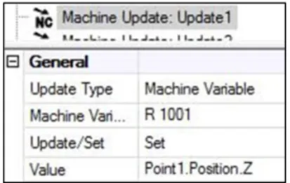
Once all the points on the artefact have been probed the
routine then stores a single value for each point as an ‘R’
variable on the machine controller; for points approached in the x-direction the x-coordinate is stored in the machine coordinate system; similarly the y-coordinate is stored for points approached in the y-direction; and the z-coordinate is stored for points approached in the z-direction. This can be implemented in Renishaw Productivity+ software by using the Machine Update command to set a variable, Figure 3 shows the Z-coordinate of Point 1 being written to the machine
variable R1001. ‘R’ variables are used on Siemens
controllers, other controllers use different naming conventions for variables.
Fig. 3: Machine Update writing the Z-coordinate of Point 1 to the machine variable R1001
For each variable two further variables are then calculated
and stored as ‘R’ variables by adding or subtracting a
tolerance value respectively; a maximum permissible value and a minimum permissible value. The Figure 4 below shows this implemented in G-Code as a G-Code Block in the Renishaw Productivity+ software. The tolerance is first defined as R1300, this is then subtracted from the measured values of Points 1 to 5 (R1001 to R1005) to give the minimum permissible values for these points (R1101 to R1105). Similarly the tolerance is added to the measured values to give the maximum permissible values (R1201 to R1205).
Fig. 4: G-Code used to create
Min/Max values Fig. 5: Baseline Routine
At this stage the Baseline routine, Figure 5, is complete. The as-calibrated state of the machine tool has been captured as a number of coordinate values for measurements of the artefact and these have been stored on the machine controller.
The Verify Routine is run immediately before any critical operation is carried out. The artefact is first loaded into the same position as it was for the Baseline routine using some form of repeatable fixturing as described above. The points on the artefact which were probed during the Baseline routine are then probed in exactly the same way. The values measured during the Verify routine are then compared with the minimum and maximum permissible values created by the Baseline routine and if any values are out of tolerance then a fault is flagged. This may be used to immediately stop the process and alert the attention of maintenance personnel or it may first initiate additional automated diagnostics, for example running a clean cycle on the artefact before re-running the Verify routine.
The comparison of the measurements made during the Verify routine with the stored minimum and maximum permissible values can be implemented in Renishaw
Productivity+ software using conditional logic (If-Then-Else statements) as shown in the flow chart below. It would also be possible to implement this process using G-code and macro programming.
5.Process Trials
Initial development of the baseline and verification cycles involved proving the concept of artefact probing for machine tool verification and optimizing cycles in order to minimize the verification process time. The baseline routine cycle time is relatively unimportant since this is only run once; after calibration. Calculation of minimum and maximum tolerance values was therefore moved into this program resulting in a larger number of variables required but reducing process time significantly. Although the simple arithmetic would not be expected to add any significant time it was found that it could add up to a minute to the cycle. It is thought that this may be due to different computer systems being used within the control of the machine tool and therefore the requirement to open and close communication ports when variables are being written and calculated within a probing cycle.
Initial tests involved a more complex artefact used for 3-axis probing. It was found that the number of features on this artefact was unnecessary and resulted in inspection times of a few minutes. Repeatability tests were performed over a number of weeks to demonstrate the stability of the process on the XYZ 1020 Vertical Milling Centre.
Fig..6: Initial Artefact used for 3-Axis Probing
A novel Poka-Yoke kinematic mount was constructed to allow long term repeatability tests to be carried out with the artefact removed and the machine used for other operations between tests. This was found to have a repeatability of approximately 1 micron. A cover plate with integral T-Slots was also produced so that the kinematic mount could be protected and machining carried out within the verified volume. This was particularly relevant when used for 5-axis machining on the rotary table.
Currently a full 5-axis artefact verification probing cycle including rotations using rotary table takes about 2 minutes and 50 seconds which shows sensitivity to 12 um on the XYZ machine. The design of the artefact was also optimized, in order to reduce the model complexity and introduce new features which allow faster probing cycle and backlash detection.
Testing of the artefact probing process was carried out at the National Composite Centre (NCC) on a 3-axis Haas VF-4 machine tool. As this machine has a Haas controller rather than a Siemens controller as used in the previous tests the variable naming convention was changed from numbers starting with ‘R’ to numbers starting with ‘#’. The variable
range available was also more restricted so that the number allocation was compressed as detailed in Table 2.
Table 1 – Variable Names
Tolerance #800
Measured Baseline Coordinates #801-#825 Minimum Coordinate Values #826-#850 Maximum Coordinate Values #851-#875
Error Flags #876-#878
The verification tolerance was reduced progressively from 20 microns down to 4 microns showing sensitivity of the process to this level. Testing of the artefact probing process was carried out at the Rolls-Royce Learning and Development Centre in Derby on a 5-axis Hermle C20U machine tool with a Siemens 840D controller, over a 3 day period. On the first day a post processor was created and initial tests were carried out using our Baseline routine and parameters within the post processor were optimized in order to allow the post processed probing routine to run on this machine tool.
Fig. 7: Artefact Probing on Hass Machine Tool at the NCC
Other practical issues of running the process on a new machine were identified as ensuring clearance when the artefact is rotated on the A and B axes, meaning that it had to be mounted in a vice and not directly on the bed, and simply getting the machine to update work offsets and copy in part programs. It was also found that clearance moves were missing from the verify cycle, presumably due to syntax differences in the G-Code implementation.
The baseline routine ran without any issues. The verify routine showed errors in the z-axis and stopped the machine. The tolerance for failure was increased to 25 microns but the machine continued to fail. This was surprising as it was a new machine which was expected to have a repeatability of around 1 micron.
Further investigations and debugging were carried out to identify the source of the verification failure. Initially a check cycle was created, this calculated the difference between each probed point and the baseline measured value, and then wrote
all of these values to R-variables. This showed that the repeatability of probing coordinates was within 7 microns for the x and y directions but there were occasional very large errors of up to 6 mm in the z-direction. After reloading and rerunning the errors went away but then came back and were seen on different points but always in z-direction.
Discussions with Rolls-Royce staff identified reliability issues with the particular probe and it was therefore assumed that the large errors causing the machine to fail the verification test were due to probe faults. The verification test therefore successfully identified that there was an issue with this machine.
6.Conclusions
The solution toolkit described provides options to deal with large and small machines, different levels of error detection and thermal effects. The artefact probing process is shown to have sensitivity to each kinematic error with examples given for large and small machines using modular and monolithic artefacts respectively. Guidance is also given on the diagnostic procedures to be carried out should a machine fail the verification test.
Testing is described of the verification methods which have been successfully demonstrated within the LIMA machine tool laboratory at the University of Bath, at the National composite centre and at the Rolls-Royce Learning and Development Centre in Derby.
Acknowledgements
This work was funded by a Technology Strategy Board UK (TSB) SAMULET I 6.3.1 project via Rolls-Royce plc. The work is also supported by the EPSRC funded Industrial Doctorate Centre in Systems (Grant EP/G037353/1) and the LIMA group at the University of Bath.
Thanks are given to Renishaw plc., IBS Precision Engineering BV and the National Composites Centre (UK) for their support in developing and demonstrating aspects of the machine tool verification system. Particular thanks are given to Mr. Nicholas Orchard for all his contribution, without which this work would not have been possible.
References
[1] Kwon, Y., Y.M. Ertekin, and B. Tseng, In-process and post-process quantification of machining accuracy in circular CNC milling. Machining Science and Technology, 2005. 9(Compendex): p. 27-38.
[2] Schlesinger, G., F. Koenigsberger, and M. Burdekin, Testing Machine Tools. 1978, London: Machinery Publishing Co.
[3] ISO, Test code for machine tools — Part 1: Geometric accuracy of machines operating under no-load or finishing conditions, in ISO 230-1. 1996.
[4] Schwenke, H., W. Knapp, H. Haitjema, A. Weckenmann, R. Schmitt, and F. Delbressine, Geometric measurement and compensation of machine – An update. CIRP Annals - Manufacturing Technology, 2008. 57: p. 660-675.
[5] ISO, Test code for machine tools — Part 2: Determination of accuracy and repeatability of positioning numerically controlled axes, in ISO 230-2. 2006.
[6] ISO, Test code for machine tools - Part 9: Estimation of measurement uncertainty for machine tool tests, in ISO 230-9. 2005.
[7] Automated Precision Inc. XD Laser. 2013 [cited; Available from: http://www.apisensor.com/xd-laser.
[8] Etalon. Applied Traceability. 2008 [cited 2008 10th November]; Home Page]. Available from: http://www.etalon-ag.com/.
[9] Choi, J.P., B.K. Min, and S.J. Lee, Reduction of machining errors of a three-axis machine tool by on-machine measurement and error compensation system. Journal of Materials Processing Technology, 2004. 155-156(Compendex): p. 2056-2064.
[10] ISO, Test code for machine tools - Part 4: Circular tests for numerically controlled machine tools, in ISO 230-4. 2005.
[11] Lei, W.T., M.P. Sung, W.L. Liu, and Y.C. Chuang, Double ballbar test for the rotary axes of five-axis CNC machine tools. International Journal of Machine Tools and Manufacture, 2007. 47(Compendex): p. 273-285. [12] Akinori, S., Measuring method of geometric error of turning shaft, 2004,
patent number: JP2004219132
[13] Kam, L., On-machine ballbar system and method for using the same, 1997, patent number: WO9718436
[14] Chen, C.-K., W.-Y. Jywe, and C.-H. Liu. Several newly developed contouring systems for testing the dynamic performance and geometric errors of CNC machine tools. in Proceedings of the second International Symposium on Instrumentation Science and Technology, August 18, 2002 - August 22, 2002. 2002. Jinan, China: Harbin Institute of Technology.
[15] Jywe, W.-Y. and C.-H. Liu. A study of geometric error measurement of cnc machine tools using the improved planar encoder system. in 2003 ASME Design Engineering Technical Conferences and Computers and Information in Engineering Conference, September 2, 2003 - September 6, 2003. 2003. Chicago, IL, United states: American Society of Mechanical Engineers.
[16] Lei, W.T. and Y.Y. Hsu, Accuracy test of five-axis CNC machine tool with 3D probe-ball. Part I: Design and modeling. International Journal of Machine Tools and Manufacture, 2002. 42(Compendex): p. 1153-1162. [17] Lei, W.T. and Y.Y. Hsu, Accuracy test of five-axis CNC machine tool
with 3D probe-ball. Part II: Errors estimation. International Journal of Machine Tools and Manufacture, 2002. 42(Compendex): p. 1163-1170. [18] Lei, W.T. and Y.Y. Hsu, Error measurement of five-axis CNC machines
with 3D probe-ball. Journal of Materials Processing Technology, 2003. 139(Compendex): p. 127-133.
[19] Trapet, E., J.-J. Aguilar Martin, J.-A. Yague, H. Spaan, and V. Zeleny, Self-centering probes with parallel kinematics to verify machine-tools. Precision Engineering, 2006. 30: p. 165-179.
[20] Yague, J.A., J. Velazquez, J.A. Albajez, J.J. Aguilar, M.A. Lope, and J. Santolaria, Development and calibration of self-centring probes for assessing geometrical errors of machines. Measurement Science and Technology, 2009. 20(Compendex).
[21] Yague, J.-A., J.-J. Aguilar, J.-A. Albajez, and J. Santolaria, Characterisation of 1D opto-electronic sensors and their application to angular self-centring probes for machine-tool verification. Measurement: Journal of the International Measurement Confederation, 2008. 41(Compendex): p. 1113-1123.
[22] Florussen, G.H.J. and H.A.M. Spaan. Dynamic R-test for rotary tables on 5-axes machine tools. 2012. Zurich, Switzerland: Elsevier.
[23] IBS Precision Engineering. IBS - Rotary axis inspector. 2013 [cited 10th April 2013]; Available from:
http://www.ibspe.com/category/machine-tool-inspection-and-analyzer-solutions/rotary-axis-inspector.htm.
[24] Bozich, D., In-line probing for process improvement. Quality, 2006. 45(Compendex): p. 52-56.
[25] Abdul, W.K., C. Wuyi, and W. Lili. Machine tools error characterization compensation by on-line measurement of artifact. in International Conference on Optical Instruments and Technology - Optoelectronic Measurement Technology and Systems. 2009. Shanghai, China: SPIE. [26] Bozich, D., Artifact probing unlocks higher machining accuracies.
Manufacturing Engineering, 2004. 133(Compendex).
[27] Hellier, Method for Measuring an Object, 2009, patent number: US2009235547
[28] ISO, Test conditions for machining centres - Part 7: Accuracy of a finished test piece, in 10791-7. 1998.
[29] Tlustry, J., System and methods for testing machine tools Microtechnic 1959. 13(162).
[30] IBS Precision Engineering. IBS - Spindle Inspector. 2013 [cited 2013 16th April]; Available from: http://www.ibspe.com/category/machine-tool-inspection-and-analyzer-solutions/spindle-inspector.htm.
[31] Gordon, L., Probing for productivity. American Machinist, 2005. 149: p. 36-41.
[32] Lee, E.S., C.H. Lee, and S.C. Kim, Machining accuracy improvement by automatic tool setting and on machine verification. Key Engineering Materials, 2008. 381-382: p. 199-202.
![Fig. 1: Deviations from straight line motion [3]](https://thumb-us.123doks.com/thumbv2/123dok_us/1993025.2796095/2.892.131.394.131.365/fig-deviations-straight-line-motion.webp)