This item was submitted to Loughborough's Research Repository by the author.
Items in Figshare are protected by copyright, with all rights reserved, unless otherwise indicated.
Reducing ground reaction forces in gymnastics’ landings may increase
Reducing ground reaction forces in gymnastics’ landings may increase
internal loading
internal loading
PLEASE CITE THE PUBLISHED VERSION PUBLISHER © Elsevier VERSION AM (Accepted Manuscript) LICENCE CC BY-NC-ND 4.0 REPOSITORY RECORD
Mills, Chris, Matthew T.G. Pain, and Maurice R. Yeadon. 2019. “Reducing Ground Reaction Forces in Gymnastics’ Landings May Increase Internal Loading”. figshare. https://hdl.handle.net/2134/4931.
This item was submitted to Loughborough’s Institutional Repository (https://dspace.lboro.ac.uk/) by the author and is made available under the
following Creative Commons Licence conditions.
For the full text of this licence, please go to:
Journal of Biomechanics, 2009, 42 (6), 671-678
Reducing ground reaction forces in gymnastics’ landings may increase internal loading
Chris Mills1, Matthew T.G. Pain2 and Maurice R. Yeadon2
1
School of Sport and Health Sciences, University of Exeter, St. Luke’s Campus, EX1 2LU.
2
School of Sport and Exercise Sciences, Loughborough University, Ashby Road, Loughborough, LE11 3TU.
Abstract
The aim of this study was to use a subject-specific seven link wobbling mass model of a gymnast, and a multi-layer model of a landing mat, to determine landing strategies that minimise ground reaction forces (GRF) and internal forces. Subject-specific strength parameters were determined that defined the maximum voluntary torque/angle/angular velocity relationship at each joint. These relationships were used to produce subject-specific ‘lumped’ linear muscle models for each joint. Muscle activation histories were optimised using a Simplex algorithm to minimise GRF or bone bending moments for forward and backward rotating vault landings. Optimising the landing strategy to minimise each of the GRF reduced the peak vertical and horizontal GRF by 9% for the backward rotating vault and by 8% and 48% for the forward rotating vault, compared to a matching simulation. However, most internal loading measures (bone bending moments, joint reaction forces and muscle forces) increased compared to the matching simulation. Optimising the landing strategy to minimise the peak bone bending moments resulted in reduced internal loading measures, and in most cases reduced GRF. Bone bending moments were reduced by 27% during the forward rotating vault and by 2% during the backward rotating vault landings when compared to the matching simulations. It is possible for a gymnast to modify their landing strategy in order to minimise internal forces and lower GRF. However, using a reduction in GRF, due to a change in landing strategy, as a basis for a reduction in injury potential in vaulting movements may not be appropriate since internal loading can increase.
Keywords: forces, impact, simulation, muscle driven, activation
Introduction
In Men’s Artistic Gymnastics a successful landing from a dismount can make the difference between winning and losing (Takei, 1998). Judging criteria for landings in gymnastics stipulate that gymnasts must land with a single placement of the feet (no additional steps) with the centre of mass over the base of support. Any steps or unsteadiness, excessive arm swinging or loss of balance can result in a score deduction between 0.1 and 0.5 (Federation Internationale de Gymnastique, F.I.G., 2001).
Landing imposes forces on the body that must be absorbed primarily by the musculo-skeletal components of the lower extremities. If the forces become too great for the body to accommodate, an injury may occur (Dufek and Bates, 1990). It has been reported that between 57% and 82% of injuries in gymnastics are acute, ranging from strains and sprains to fractures and dislocations, and the lower extremity is the most injured, comprising 54% to 70% of all injuries (Andrish, 1985; Jensen, 1998; McAuley et al., 1987; Meeusen and Borms, 1992; Snook, 1979). Thirty one percent of acute injuries are fractures to the femur and tibia/fibula (Pettrone & Ricciardelli, 1987).
Any landing in gymnastics poses a problem for gymnasts as they must trade off increased technical difficulty against the possibility of a less than perfect performance. Increased technical difficulty will potentially give the high score required to win but this is coupled with an increased probability of a faulty landing and an increased risk of injury. The landing errors observed by McNitt-Gray (2000) indicate that gymnasts have difficulty when attempting to satisfy both safety and performance objectives.
An increase in skill complexity can be associated with an increase in the height required to complete the skill (Takei, 1988; King et al., 1999). Ground impact forces generally increase with greater drop height (Dufek and Bates, 1990; McNitt-Gray et al., 1993) and greater impact forces suggest a greater injury risk to the lower extremity. The landing strategies of the gymnast and the landing mat characteristics have been identified as key factors in the dissipation of forces during landing (Dufek and Bates, 1990; McNitt-Gray et al., 1993). A gymnast can voluntarily modulate the external loading experienced during impact, therefore it may be possible for the gymnast to minimise the internal forces by altering the muscle recruitment/activation patterns (McNitt-Gray et al., 1990).
To investigate different landing strategies experimentally would risk injury to the gymnast. An alternative is to use a forward dynamics computer simulation model of a gymnast and competition-landing mat to investigate how modifications to landing strategies affect the ground reaction forces (GRF) and internal forces (joint reaction forces (JRF), musculo-tendinous forces and bone bending moments) experienced by the gymnast. In a forward dynamics simulation model the JRF is calculated as the sum of the force vectors at the joint that arise from the mechanical systems (e.g.: rigid bodies, springs and linear actuators) that are present in the simulation. In the gymnast model JRF are similar to bone on bone forces (although in this study forces generated by passive structures such as ligaments will be ignored). The aim of this study is to use a subject-specific seven link wobbling mass muscle driven model of a gymnast and a multi-layer model of the landing mat, to determine landing strategies that minimise GRF and internal forces. The level at which injury will occur will be not be specified as, apart from rare individual estimates (e.g. Zenicke et al., 1977), there are no known in vivo values for subject-specific injuries. Hence, only the generic risk of injury from increased loading can be assessed rather than the probability of injury.
Methods
A planar forward dynamics seven link wobbling mass model representing the gymnast was constructed in visualNastran 4D (VN4D) to simulate the first 100 ms of landing on a competition gymnastics mat (Mills et al., 2008). The gymnast model comprised head + trunk, arm + hand, thigh, shank segments and a two-segment foot with pin joints connecting adjacent links at their ends on the longitudinal axis of each segment (Figure 1a). The arm segment incorporated a fixed joint at the elbow to define the orientation of the upper and lower arm which differed between vault type but remained relatively constant throughout a trial. Wobbling masses were connected via non-linear spring dampers to the rigid links of the trunk, thigh and shank to represent soft tissue movement. The fixed links of the shank and thigh were each made of two parts connected by a rigid joint so that moments could be calculated in the middle of these links. Using the two part link to calculate bending moments is a simple method to determine the magnitude of the loading on the skeletal structure and can be related to the fracture failure of bones from in-vitro tests. However, live bone is normally stronger than in-vitro bone specimens and also has the advantage that muscle and other soft tissue surround it. These tissues can reduce the loading on the bone but were not accounted for in the simulations. Joint reaction forces and bone bending moments were calculated throughout the simulations.
The landing mat model parameters were determined through material tests (Pain et al., 2005) and the model was implemented in VN4D. The landing mat model comprised three layers each separated by a spring damper system (Mills et al., 2006). The landing mat model was separate from the gymnast model (Figure 1a).
(a)
(b)
Figure 1. (a) Seven-segment model of a gymnast and landing mat; (b) Mechanical structure of the knee extensor lumped muscle model (linear actuator) and the series elastic component (SEC).
Personalised segmental inertia parameters for the gymnast were calculated using the inertia model of Yeadon (1990); these were then divided into the fixed and wobbling mass inertial parameters based upon Pain and Challis (2006). A ‘lumped’ muscle model in the form of a linear actuator represented all the muscles responsible for a particular joint’s flexion and a similar muscle model was used for extension (Figure 1b) (Mills et al., 2008). This allowed the linear actuator to act with a moment arm scaled to the subject from the middle of the ranges found in Duda et al. (1996) and Jacobs et al. (1996).
Subject-specific strength parameters for the gymnast’s lumped muscles were calculated using a nine-parameter mathematical function determined from isokinetic dynamometer
testing of the subject (Yeadon et al., 2006; King et al., 2006; Mills et al., 2008). A series of maximal effort isometric and eccentric – concentric cycles on a dynamometer helped to determine muscle model parameters. The nine-parameter mathematical function represented the maximum voluntary torque/angle/angular velocity relationship for each joint. This function was multiplied by the muscle’s activation profile to give the torque produced at the joint at any moment in time (Mills et al., 2008). The muscle models were implemented in MatLab, and Simulink was used to integrate the VN4D link model, the muscle models and the optimisation routines.
The gymnast-mat model has been evaluated using results from experimental forward and backward rotating somersault vaults (Mills et al., 2008). In this process matching simulations of the real vaults were produced by minimising the kinematic and kinetic differences between the recorded performances and the model performance as detailed in Mills et al. (2008). The gymnast model was based on an international competitive gymnast (height 1.77 m, weight 75 kg) performing a forward and backward rotating somersault vault in a simulated competition environment (Mills et al., 2008). The gymnast-mat model produced matching simulations of the landings with overall kinematic and kinetic errors of 10 – 15% (Mills et al., 2008). Initial conditions comprising limb and whole body positions, velocities and orientations for the model during optimisations were kept the same as the matching simulations.
The muscle activation timings determined via matching simulations (Mills et al., 2008) were used as a starting point for the optimisations. The gymnast-mat model was used to investigate whether it was possible to reduce the GRF, JRF, bone bending moments and muscle forces during landing through adjustments in muscle activation. The Simplex optimisation algorithm was used to determine the 12 extensor muscle activation parameters (three at the hip, knee, ankle and shoulder) required to minimise the GRF or bone bending moments experienced by the gymnast during landing. The flexor activation patterns remained the same as the matching simulations. The magnitude of the bone bending moments within the lower extremities was used as a means of assessing the risk of injury during the landings. The gymnast-mat model was not designed to specify what injuries may occur but instead used to determine whether internal forces increase or decrease. If internal measures in the model do increase this may suggest a greater injury risk to the gymnast in general.
Objective function one (S1) was used to minimise the GRF during landing.
S1 = (Fz + Fy) + penalties (1)
Fz = peak vertical ground reaction force
Fy = peak horizontal ground reaction force
Objective function two (S2) was used to minimise the internal bone moments experienced
by the gymnast during landing.
S2 = (Ms + Mt) + penalties (2)
Ms = absolute peak shank bone moment
Mt = absolute peak thigh bone moment
Constraints were placed upon the simulation during the optimisations to ensure a result that was within the limits of the human body and the F.I.G. guidelines. A penalty was added to the score if a constraint was violated. The penalties were weighted so that 100 N of GRF was equivalent to 1° in joint angle and 0.1 m/s in centre of mass velocity. The equivalence of penalties was determined from the matching trials of the model from Mills et al. (2008). It was found that similar qualitative changes in overall kinematic landing performance were
obtained for each of 100 N of GRF, 1° change in joint angle and 0.1 m/s in centre of mass velocity. The vertical GRF at the end of the simulation (after 100 ms) was limited to be between 500 N and 2000 N. This range was chosen to encompass the GRF measured during the experimental gymnast landings (Mills et al., 2008). The minimum ankle joint angle was set at 60° as this was at the limit of manually forced dorsiflexion of the subject (Mills et al., 2008). The minimum knee angle during the simulation was set at 80° as a knee angle below this was deemed by an international judge to be excessive and to be liable to a landing deduction. The minimum hip angle was set at 80° for the same reasons.
The limit for the horizontal and vertical velocities of the mass centre at the end of the simulation was based upon the gymnast being able to complete the landing by standing up. Successfully standing up without a step was only achieved by the subject, from over 30 trials, when his vertical mass centre velocity was ±1 m/s vertically and ±2 m/s horizontally at the time equivalent to the end of the matching simulation run time.
Results
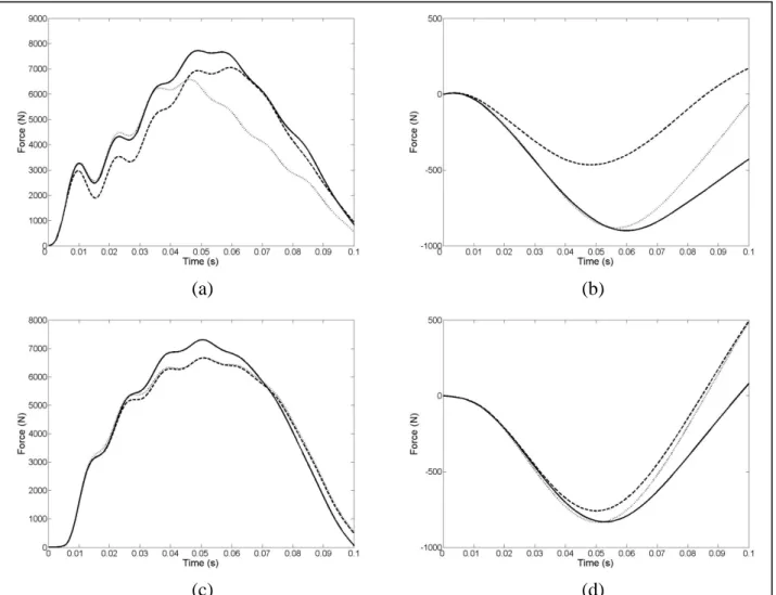
The optimisation of the landing strategy for the forward and backward rotating vaults, using S1 and S2, reduced both the peak vertical and horizontal GRF (Figure 2) when
compared with the matching simulation (Mills et al., 2008). Optimising the landing strategy to minimise the GRF (S1) reduced the peak vertical and horizontal GRF by 8% and 48% for
the forward rotating vault and by 9% and 9% for the backward rotating vault (Tables 1 and 2). Optimising the landing strategy using S2 (to minimise the internal forces) reduced the
peak vertical and horizontal GRF by 15% and 2% for the forward rotating vault and by 9% and 0% for the backward rotating vault (Tables 1 and 2).
Table 1.Comparison of peak ground and joint reaction forces, peak bone bending moments and peak muscle forces for the matching simulation and optimisations (S1 and S2) for the forward rotating vault.
Parameter (peaks) Matching Simulation Opt. (S1) Opt. (S2) VGRF 7725 N 7075 N 6582 N HGRF 900 N 465 N 882 N Ankle JRF 13543 N 12499 N 11294 N Knee JRF 10870 N 11519 N 8051 N Hip JRF 7990 N 6900 N 6117 N Ankle ext. muscle 6294 N 6406 N 5188 N Knee ext. muscle 5442 N 8022 N 4011 N Hip ext. muscle 3848 N 5936 N 2875 N Shank mom. 377 Nm 442 Nm 291 Nm Thigh mom. 266 Nm 379 Nm 182 Nm
VGRF = vertical ground reaction force HGRF = horizontal ground reaction force JRF = joint reaction force.
ext. muscle = extensor muscle force mom = bone bending moment
Table 2. Comparison of peak ground and joint reaction forces, peak bone bending moments and peak muscle forces for the matching simulation and optimisations (S1 and S2) for the backward rotating vault.
Parameter (peaks) Matching Simulation Opt. (S1) Opt. (S2) VGRF 7304 N 6667 N 6667 N HGRF 831 N 759 N 831 N Ankle JRF 13172 N 11740 N 11648 N Knee JRF 8548 N 9099 N 8726 N Hip JRF 9460 N 9138 N 8293 N Ankle ext. muscle 6882 N 6070 N 5954 N Knee ext. muscle 3580 N 4756 N 4332 N Hip ext. muscle 8388 N 8050 N 7203 N Shank mom. 306 Nm 326 Nm 305 Nm Thigh mom. 302 Nm 347 Nm 290 Nm
VGRF = vertical ground reaction force HGRF = horizontal ground reaction force JRF = joint reaction force.
ext. muscle = extensor muscle force mom = bone bending moment
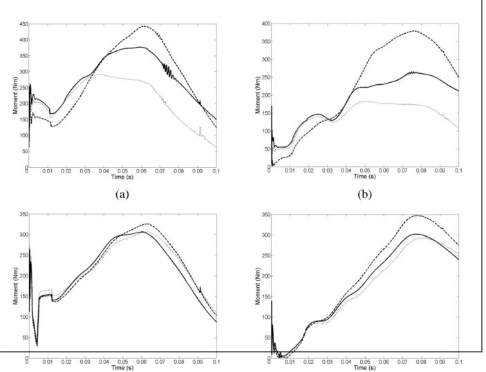
Optimising the muscle activation patterns using S1 caused peak shank bone bending
moments to increase by an average of 12% and peak thigh bone bending moments to increase by 29% over the two vaults (Figure 3) compared with the matching simulation. However, using S2 showed an average decrease of 12% in the shank bone and 18% in the thigh bone
(Figure 3). These results show that minimising the external forces alone can increase the bone bending moments within the gymnast (Tables 1 and 2).
Peak loading rates for GRF were very similar for the matching simulation, S1 and S2,
with the exception of the HGRF for the front somersault which was considerably lower for S1
(Figure 2). The average loading rates were between 10% and 25% lower in the optimised simulations compared with the matching simulation (Figure 2). Peak bone bending loading rates occurred at low loading early in the simulation and was similar for all simulations (Figure 3). The average bone bending loading rate varied from -8% to 20% across all optimisations. Although S1 tended to have slightly higher values on average no optimisation
consistently gave the highest loading rate.
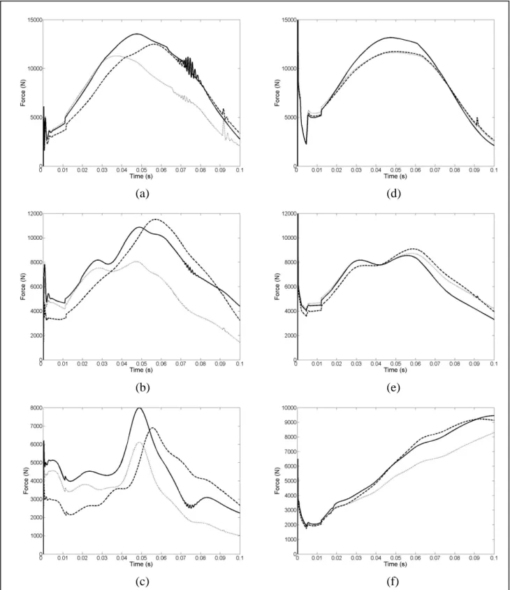
The peak JRF in the optimised landings using S1 for both vaults were about 10% lower at
the ankle and the hip but were slightly increased at the knee (Tables 1 and 2). Peak JRF occurred 1 ms to 10 ms later than in the matching simulation (Figure 4). The peak JRF in the optimised landings using S2 were lower than the optimisations using S1 and the matching
simulations, except at the knee (Tables 1 and 2). Peak JRF occurred 1 ms to 11 ms earlier than in the matching simulation (Figure 4).
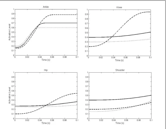
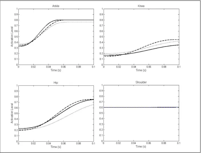
When optimising using S2 the muscle activation time histories were characterised by
higher initial activation levels than the S1 optimisations, whereas the S1 optimisations
reached higher final activations than the S2 optimisations (Figures 5 and 6). This tended to
give higher activation levels in the leg extensors for up to the first 20% - 50% of the simulation when optimising using S2 compared to S1.
(a) (b)
(c) (d)
Figure 2. Optimisation of landing strategies for forward and backward rotating vaults (a) Vertical Ground Reaction Force (VGRF) for the forward rotating vault, (b) Horizontal Ground Reaction Force (HGRF) for the forward rotating vault, (c) VGRF for the backward rotating vault, (d) HGRF for the backward rotating vault. (Solid line = matching simulation, dashed line = S1, dotted line = S2.)
(a) (b)
(c) (d)
Figure 3. Lower extremity bone bending moments during the forward rotating vault (a) shank, (b) thigh and backward rotating vault (c) shank, (d) thigh (Solid line = matching simulation, dashed line = S1, dotted line = S2.)
(a) (d)
(b) (e)
(c) (f)
Figure 4. Joint reaction forces during the optimised landing strategies for the forward and backward rotating vaults: (a) ankle – forward, (b) knee – forward, (c) hip – forward, (d) ankle – backward, (e) knee – backward, (f) hip – backward. (Solid line = matching simulation, dashed line = S1, dotted line = S2.)
Figure 5. Muscle activation histories during the optimised landing strategies for the forward rotating vault (Solid line = matching simulation, dashed line = S1, dotted line = S2).
Figure 6. Muscle activation histories during the optimised landing strategies for the backward rotating vault (Solid line = matching simulation, dashed line = S1, dotted line = S2).
Optimising using S1, peak muscle forces during the forward rotating vault increased at the
ankle (18%), knee (47%) and hip (54%) compared with the matching simulation. Peak muscle forces at ankle, knee and hip occurred at 56 ms, 68 ms and 100 ms during the optimisation (S1) compared with 48 ms, 59 ms, and 100 ms during the matching simulation.
However, all the peak muscle forces decreased: ankle (18%), knee (26%), hip (25%) when using S2 (Table 1). When optimising using S1 during the backward rotating vault peak
muscle forces decreased at the ankle (12%) and the hip (4%) but increased at the knee (33%) compared with the matching simulation. Peak muscle forces at ankle, knee and hip occurred at 52 ms, 74 ms, and 100 ms during the optimisation (S1) compared with 48 ms, 74 ms and
100 ms during the matching simulation. When optimising using S2 peak muscle forces also
decreased at the ankle (13%) and hip (14%) but increased at the knee (21%) compared to the matching simulation (Table 2).
It is important to highlight that during the forward rotating vault, the optimisation result using S2 achieved a lower GRF than using S1 (Table 1), indicating that a local minimum was
found for S1. The RMS difference between the two optimisations in terms of the GRF was
only 1%. Re-running the S1 optimisation using the results from S2 as the starting point did
Discussion
The most significant finding is that it is possible for a gymnast to modify his landing strategy in order to minimise internal forces and lower GRF. It was noted that reductions in loading were not achieved at the expense of increases in loading rate. However, the goal of minimising the GRF through changes in muscle activation, although successful, can actually increase the internal loading and hence the possibility of injury risk. This may seem counter-intuitive at first, but with peak forces for each muscle group being comparable with the peak GRF it is less surprising.
Optimising using S1 had lower initial activation levels and higher activations for the
second half of the simulation. This produced large muscle forces later in the simulation and these forces were major contributors to JRF. These large JRF occurred in a more flexed landing posture as it was later in the landing process. This resulted in the muscle forces pulling almost perpendicular to the long axis of the bone segments, leading to higher bone bending moments than in either the matching simulation or S2. When comparing Figures 2, 3
and 4 the peak bone bending moments can be seen to occur well after the peak JRF and GRF indicating that it is the geometry of the landing and the internal forces that are important. It would appear that higher levels of extensor activation at all muscles early in the landing and rapid rises in muscular activity at the ankle is the safer strategy to reduce bone bending moments, muscle forces and JRF.
For both vaults it is apparent that using S2 tends to result in a closer fit for GRF and bone
bending, especially for the first 40 ms to 50 ms of the 100 ms simulation. This may indicate that the landing goal of the gymnast may have been related to landing with minimal internal loading rather than minimising GRF. For the forward rotating vault, S1 was closest to the
vertical GRF of the matching simulation during the last 40 ms so the inference above is equivocal. A more complex feed forward activation profile that allows multiple steps may be needed even over this short timescale to investigate this area fully. It is also a limitation of this study that the flexor activation profiles were not simultaneously optimised with the extensors. This was primarily due to long simulation in run times. However, as well as these vaults, matching simulations from other types of forwards and backwards rotating vaults have been conducted. In all of these matching simulations the flexors at each joint followed the same pattern of activation. That is they decreased substantially from touchdown and with the profiles as presented in Mills et al. (2008).
The solutions found here are likely to be local minimum, near to the original matching simulation and this may be a shortcoming of the study in methodological terms; the global GRF minimum could also be associated with the lowest internal forces. However, it does not affect the major finding that not all landing techniques that reduce GRF will lead to lower internal forces and hence lower injury risk. Local solutions may also be more useful from an applied point of view as a true global solution may require very different activation patterns than the gymnast is currently using and this would necessitate major retraining with a coach to alter the landing technique. The local minimum solution suggests that through minor changes in the muscle activation patterns the gymnast would be able to reduce internal and external landing forces.
The model does not account for the three-dimensional components of multiple muscle insertions and geometry, which will change the loading patterns. It is likely that the evolutionary design of the human system predisposes itself to mitigate the loading compared to the model and therefore the bone bending moments determined here are likely to be high. The more complex structure of human legs, as described above, has a greater potential for reducing loading but it also introduces a larger set of variables and parameters. This is likely to give a greater chance of arriving at a local minimum for internal loading, as on average a greater number of local minima will exist.
The backward or forward rotation of the gymnast prior to landing may also affect the landing strategy selected. A ‘blind’ landing during forward rotating skills may mean that the gymnast chooses to increase the amount of muscle pre-activation during the flight phase and ‘over-engineer’ the landing to give more room for error (McNitt-Gray, 2000). A backward rotating skill allows the gymnast to view the landing prior to touchdown and use a more informed landing strategy. This is supported by the results of the optimisations. During the backward rotating vault there is little improvement over the matching simulation and both optimisations give very similar results, whereas the opposite is true for the forward rotating vault.
It is often inferred that improved performance by a computer simulation over the human performance being modelled is a sign that there is room for improvement in the human performance (Hiley & Yeadon, 2005; Domire & Challis, 2007; Bobbert, 2001). However, this may be incorrect if the task objectives being optimised are not the same as those that the human is optimising. In this study it was found that modifications to the landing strategy could reduce external and internal forces on the gymnast. However, the successful minimisation of GRF during landing led to higher internal loading than the matching simulation. Minimising internal bone bending moments gave low peak GRF with an initial time history that looked more similar to the matching performance and may indicate the gymnast was trying to minimise internal loading. If, in the future, quantitative assessment of landings using force measurement is employed it will be important to take into account that minimising the GRF may not be the safest landing strategy as is commonly assumed. Even without force measurements surrogate measures such as the noise or apparent abruptness of the landing may lead to coaches asking gymnast to perform landings with less force and the same considerations need to be kept in mind. In this case, where the gymnast appears to perform a landing that is close to optimal with regards to internal loading, altering their landing to reduce GRF to mitigate injury risk would have had the opposite effect.
References
Andrish, J. T., 1985. Knee injuries in gymnastics. Clinics in Sports Medicine 4, 111-121. Bobbert, M., 2001. Dependence of human squat jump performance on the series elastic
compliance of the triceps surae: a simulation study. Journal of Experimental Biology 204, 533-542.
Domire,Z., Challis, J., 2007. The influence of squat depth on maximal vertical jump performance. Journal of Sports Sciences 25, 193-200.
Duda, G., Brand, D., Freitag, S., Lierse, W., Schneider, E., 1996. Variability of femoral muscle attachments. Journal of Biomechanics 29, 1185-1190.
Dufek, J. T., Bates, B. T., 1990. The evaluation and prediction of impact forces during landings. Medicine and Science in Sports and Exercise 22, 370-377.
Federation Internationale de Gymnastique – F.I.G., 2001. Code of Points – men’s artistic gymnastics. F.I.G., Switzerland.
Hiley, M. J., Yeadon, M. R., 2005. Maximal dismounts from high bar. Journal of Biomechanics 38, 2221-2227.
Jacobs, R., Bobbert, M., van Ingen Schenau, G., 1996. Mechanical output from individual muscles during explosive leg extensions: the role of biarticular muscles. Journal of Biomechanics 29, 513-523.
Jensen, J. E., 1998. Stress fracture in a world-class athlete: a case study. Medicine and Science in Sports and Exercise 30, 783-787.
King, M. A., Yeadon, M. R., Kerwin, D. G., 1999. A two-segment simulation model of long horse vaulting. Journal of Sports Sciences 17, 313-324.
King, M. A., Wilson, C., Yeadon, M. R., 2006. Evaluation of a torque-driven model of jumping for height. Journal of Applied Biomechanics.
McAuley, E., Hudash, G., Shields, K., Albright, J., Garrick, J., Requa, R., Wallace, R., 1987. Injuries in women’s gymnastics. The American Journal of Sports Medicine 15, 558-566. McNitt-Gray, J. L., 2000. Musculoskeletal Loading During Landing. In: Zatsiorsky, V.
(Eds.), The Encyclopaedia of Sports Medicine: Biomechanics in Sport. IOC, Blackwell Science, pp. 523-549.
McNitt-Gray, J. L., Anderson, D., Barbieri, C & Cvengos, K., 1990. Adjustments in kinematics and kinetics during modified landings. In: Proceedings of XIVth ASB Meeting, 75-76.
McNitt-Gray, J. L., Yokoi, T., Millward, C., 1993. Landing strategy adjustments made by female gymnasts in response to drop height and mat composition. Journal of Applied Biomechanics 9, 173-190.
Meeusen, R., Borms, J., 1992. Gymnastic injuries. Sports Medicine 13, 337-356.
Mills, C., Pain, M. T. G., Yeadon, M. R., 2006. Modelling a viscoelastic gymnastics landing mat during impact. Journal of Applied Biomechanics 22, 103-111.
Mills, C., Pain, M. T. G., Yeadon, M. R., 2008. The influence of simulation model complexity on the estimation of internal loading in gymnastics. Journal of Biomechanics 41, 620-628.
Pain, M.T.G., Challis, J. H., 2006. The influence of soft tissue movement on ground reaction forces, joint torques and joint reaction forces in drop landings. Journal of Biomechanics 39, 119-124.
Pain, M. T. G., Mills, C., Yeadon, M.R., 2005. Video analysis of the deformation and effective mass of gymnastics landing mats. Medicine and Science in Sports and Exercise 37, 1754-1760.
Pettrone, F., Ricciardelli, E., 1987. Gymnastic injuries: the Virginia experience 1982-1983. The American Journal of Sports Medicine 15, 59-62.
Snook, G. A., 1979. Injuries in women’s gymnastics. The American Journal of Sports Medicine 7, 242-244.
Takei, Y., 1988. Techniques used in performing handspring and salto forward tucked in gymnastics vaulting. International Journal of Sports Biomechanics 4, 260-281.
Takei, Y., 1998. Three-dimensional analysis of handspring with full turn vault: deterministic model, coach’s beliefs and judges’ scores. Journal of Applied Biomechanics 14, 190-211. Yeadon, M. R., 1990. The simulation of aerial movement – II. A mathematical inertia model
of the human body. Journal of Biomechanics 23, 67-74.
Yeadon, M. R., King, M. A., Wilson, C., 2006. Modelling the maximum voluntary joint/angular velocity relationship in human movement. Journal of Biomechanics 39, 476-482.
Zernicke, R. F., Garhammer, J., Jobe, F. W., 1977. Human patellar-tendon rupture. Journal of Bone and Joint Surgery 59, 179-183.