INSTRUCTION SHEET
S4560
AUTOMATIC IGNITION CONTROL
APPLICATION
The S4560 provides automatic ignition and control for burners in accordance with EN 298.
SPECIFICATIONS
ModelS4560: 220 ... 240 V, 50 Hz.
Suffix A: For atmospheric burners. Non volatile lock out in accordance with EN 298.
Suffix B: As suffix A except a built in flame indication relay for modulating applications.
Suffix C: For fan assisted applications. Non volatile lock out in accordance with EN 298.
Suffix D: As suffix C except a built in flame indication relay for modulating applications.
Suffix E: As suffix A except lock--out after flame lost during normal operation.
Suffix P: As suffix A except volatile lock out, reset by interrupting heat demand.
Suffix Q: As suffix B except volatile lock out, reset by interrupting heat demand.
Suffix R: As suffix C except volatile lock out,reset by interrupting heat demand.
Suffix T: As suffix D except volatile lock out, reset by interrupting heat demand.
Dimensions See fig. 9.
Ambient temperature 0 ... 60_C
Relative humidity
90% max. at 40_C (non condensing)
Supply voltage
Line voltage, 220 V (--15%) ... 240 V (+10%), 50 Hz (¦2 Hz)
Power consumption 10 VA max. Electrical rating
Valve(s) output: 1 A max cos♥>0.6
Fan output (Suffix C, D, R and T): 1 A max cos♥>0.6 Alarm output: 1 A max cos♥>0.6
Flame indication relay: 1 A max cos♥>0.6 External ignition transformer: 1 A max cos♥>0.6 All outputs together: 3 A max.
Electrical connection
High tension spark: 2.8 x 0.5 mm spade terminal. Flame rod and ground: 6.3 x 0.8 or 4.8 x 0.8 mm spade
terminal (depending on O.S. number). Multiple connector: Molex 3001 series
Timing (depending on O.S. number)
Waiting time (Tw)/Prepurge time (Tp): 0 ... 24 s Safety time (Ts): 0 ... 250 s
Stabilization time (Tstab): 0 ... 15 s
Flame sensing
Flame sensing is based on the rectification principle. Minimum flame current: 0.7←A
Response time ”ON”: < 200 ms (at 2←A flame current) Response time ”OFF”: < 1 s
Maximum cable length: 1 m
Not protected against electrical shock. Ignition
Integral electronic spark generator Spark voltage: 12 kV at 40 pF load Repetition rate: 12 Hz
Maximum cable length: 1 m
Not protected against electrical shock.
Contents
English. . . . Page 1 ... 10 Deutsch . . . . Seite 11 ... 13 wi thout not ic e. Pr in te d in the Net her lands.Fusing
Automatic ignition control should be externally fused to prevent damage to automatic ignition control, wiring or periferals.
External fuse: 16 A slow max. Enclosure
IP 00
Recommended flame sensor
Q375 Spark igniter or flame sensing electrode Q354 Flame sensor
Accessories (to be ordered separately)
Multiple connectors including 1 m leads, order number: 3 pole (suffix B, C, Q and R): . . . 45.900.419--002 5 pole(suffix A, B, C, D and E ): . . . 45.900.419--003 6 pole (suffix D and T): . . . 45.900.419--004 High voltage cable (500 mm): . . . 45.900.411--001
SYSTEM OPERATION
IMPORTANT
The automatic ignition controlsS4560P, Q, R, and Tdo not have an independant manual reset function. The application of these types is therefore restricted to only those applications where resetting by switching off the heat demand is allowed.
Automatic ignition control for atmospheric appliances See fig. 3. and 4. for suffix A, B, P and Q and fig 7. for suffix E When there is a call for heat, a waiting period (Tw) elapses
before built--in or external igniter and gas valve is switched on.
Ignition spark ignites gas and resulting flame is detected by the flame rod.
Internal ignition is switched off immediately after flame is established and --if appropiate-- external ignition is switched off after elaps of stabilisation time.
If flame is not established within the safety time (Ts), the
automatic ignition control locks--out.
If flame is lost during normal run, the automatic ignition control repeats start sequence (except suffix E).
In case of ignition control with LPG valve connection, gas pressure switch and TTB switch, the ignition control waits for gas pressure before normal sequence is started.
If TTB switch becomes active all valves are de--energized. The TTB switch has to be reset before sequence will start again.
Automatic ignition control for fan assisted appliances See fig. 5. and 6. for suffix C, D, R and T
When there is a call for heat, fan is energized if air proven switch is in the ”NO AIR” position.
When sufficient air flow is proven by the air proving switch, a prepurge period (TP) elapses before built--in or external igniter
and gas valve is switched on.
Ignition spark ignites gas and resulting flame is detected by the flame rod.
Internal ignition is switched off immediately after flame is established and --if appropiate-- external is switched off after elaps of stabilisation time.
If flame is not established within the safety time (T), the
If air flow is not proven by air proving switch, automatic ignition control will remain in a waiting mode with fan energized.
If flame is lost during normal run, the automatic ignition control repeats start sequence.
WARNING
If fan/air proving switch response time is1 s, an orifice in the air flow switch tube must be mounted in order to avoid cycling.
lock- out reset
The auto ignition control will be reset by either depressing the internal or the external reset button in the external wiring (suffix A, B, C, D and E) or by interrupting the power supply (suffix P, Q, R and T).
If a first reset is not succesful wait at least 15 seconds before making another reset.
INSTALLATION AND CHECKOUT
IMPORTANT
Installer must be a trained experienced service man. Disconnect power supply to prevent electrical shock and/or equipment damage.
Before installing or replacing any control check that type number is correct for the application. Never use a type with a larger safety time for which the appliance is approved.
The appliance manufacturer’s instructions should always be followed when provided. If such instruc-tions are not provided see fig. 11. ... 19. for typical systems.
Ensure combustion chamber is free of gas before start up.
Conduct a thorough check out when installation is completed.
At the first start the automatic ignition control can be in lock--out; reset to free the control.
WARNING
After moving S4560 automatic ignition control from outdoor to indoor conditions, condensation may occur. Do not connect condensated automatic ignition control to mains.
Mounting
The automatic ignition control should be mounted on a flat surface by means of 4 mounting holes (see fig. 9.). Mounting position
The automatic ignition control functions position independently.
To ensure reliable long term operation mount automatic ignition control at a position in the appliance with a low ambient temperature and low radiation.
Wiring
CAUTION
Wiring must be in accordance with local regulations. Never combine high tension wiring with other wiring.
Use untinned receptacles for easier connection.
Use leadwire which can withstand 105_C ambient.
Use leadwire which is proven against moisture.
Wiring between automatic ignition control and spark sensing electrode should have good quality insulation, suitable for the temperatures encountered.
Length of wiring for external components: 1 m max. Wiring to automatic ignition controls (see fig. 1.)
1. Ground wire has large self inductance due to long length. 2. High tension wire has large capacitive coupling to other
wire
Results of 1. and 2. :
Sparks and flash over on PCB Damage of PCB other Fl Gnd HT other Fl Gnd HT < 20 cm Shield metal Metallisch Umgebung Metalen ommanteling > 10 cm
Fig. 1. Wiring to automatic ignition control Bild 1. Verdrahtung des Gasfeuerungsautomats Fig. 1. Bedrading van de branderautomaat
Supply voltage polarity
WARNING
If automatic ignition control seems to operate normally but does not detect ignition flame, check for right polarity of power supply (line, neutral).
Spark gap
Refer to the appliance manufacturer’s instructions for recommended ignition electrode position.
Maximum allowable spark gap: 3.5 mm. Checking flame current
The minimum value should be 0.7←A.
To check flame current connect a DC micro--Ampèremeter between flame sensing wire and flame sensor rod.
If flame current is insufficient check that flame sensing rod is fully enveloped by the flame and that burner is reliable grounded to automatic ignition control.
Checkout
After installation, set burner system in operation and observe through a complete cycle to ensure that burner system components function correctly.
GENERAL CONSIDERATIONS
The automatic ignition control should be externally fused. The automatic ignition control contains no serviceable parts. Any attempt of replacement of parts will affect the safety of this device and is therefore not allowed.
High temperatures will affect product life.
When the automatic ignition control is built in an appliance, the total protection must be IP 40 at least.
To ensure reliable long term operation, mount automatic ignition control at a position in the appliance with a low ambient temperature and a low radiation.
For safety a high limit thermostat must be connected in series with the comfort controls to de--energize the automatic ignition control in case of over temperature.
To suppress Radio Frequency Interference (RFI) the spark electrode cabling should be mounted in a sufficient shielded environment.
NOTE: Electrical rating of connected controls and air proving switch should be appropriate for the load that is switched by the automatic ignition control. NOTE: The emission level in accordance with EN 55014
generated by the electronic ignition is in some applications higher than allowed and need to be checked.
¯
P¯
TTB GPSGB
D
NL
Thermostat Temperaturregler Regelthermostaat
Gas valve Gasventil Gasklep
Ignition Zündung Ontsteking
Fan Gebläse Ventilator
Flame rod Ionisationselektrode Ionisatie--elektrode
Limiter Begrenzer Maximaal beveiliging
Reset switch Entriegelung Ontgrendeling
Flame indication relay Flammenmelderelais Vlamindicatierelais
Air proving switch Luftdruckschalter Luchttransportschakelaar
Gas pressure switch Gasdruckwächter Gasdrukschakelaar
External ignition transformer Externe Zündeinheit Externe ontsteektransformator
Alarm Alarm Alarm
Down draught supervision Rauchgasüberwachung Thermische terugslag beveiliging
Fig. 2. Legend Bild 2. Legende Fig. 2. Legenda
t1 t2 t3 t5 t6 Tw t7 Ts Tw t4 t0 Tstab
Fig. 3. Functional diagram S4560A, B, P, Q with potential free flame relay connection Bild 3. Programmablauf S4560A, B, P, Q mit
spannungsfreiem Flammenrelais Anschluss Fig. 3. Functie diagram S4560A, B, P, Q met
spanningsvrije vlamrelais aansluiting
V1& V2 t1 t2 t3 t5 t6 Tw t7 Ts Tw t4 t0 Tstab
Fig. 4. Functional diagram S4560A, B, P, Q Bild 4. Programmablauf S4560A, B, P, Q Fig. 4. Functie diagram S4560A, B, P, Q
V1 V2 t0 t1 t3 t5 Tp t7 P t2 t4 t6 Ts Tp Tstab
Fig. 5. Functional diagram S4560C, D, R, T with potential free flame relay connection Bild 5. Programmablauf S4560C, D, R, T mit
spannungsfreiem Flammenrelais Anschluss Fig. 5. Functie diagram S4560C, D, R, T met
spanningsvrij vlamrelais aansluiting
V1& V2 t0 t1 t3 t5 Tp t7 P t2 t4 t6 Ts Tp Tstab
Fig. 6. Functional diagram S4560C, D, R, T Bild 6. Programmablauf S4560C, D, R, T Fig. 6. Functie diagram S4560C, D, R, T
V1
t1 t2 t3 t5
Tw
t4
t0
Tstab
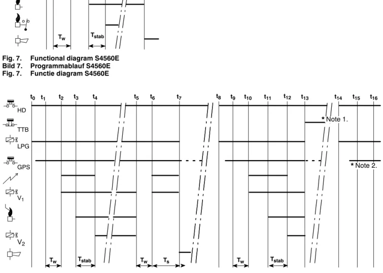
Fig. 7. Functional diagram S4560E Bild 7. Programmablauf S4560E Fig. 7. Functie diagram S4560E
V1& V2
*Note 1. : S4560B, Q is waiting for manual reset on TTB switch
S4560B, Q wartet auf Entriegelung des Rauchgasüberwachungsschalters S4560B, Q wacht op ontgrendeling van de TTB schakelaar
*Note 2. : S4560B, Q is waiting for gas pressure S4560B, Q wartet auf Gasdruck S4560B, Q wacht op gasdruk
t0 t1 t2 t3 t4 t5 t7
Ts
Fig. 8. Functional diagram S4560B,Q with LPG valve, GPS and TTB switch
Bild 8. Programmanlauf S4560B,Q mit LPG Ventil, Gasdruckwächter und Rauchgasüberwachungsschalter Fig. 8. Functie diagram S4560B,Q met LPG gasklep, gasdruk-- en TTB schakelaar
V1 V2 GPS TTB LPG t8 t10 t11 t12 t13 t16 HD t6 *Note 1. *Note 2. t14 Tw Tstab t9 t15 Tw Tstab Tw
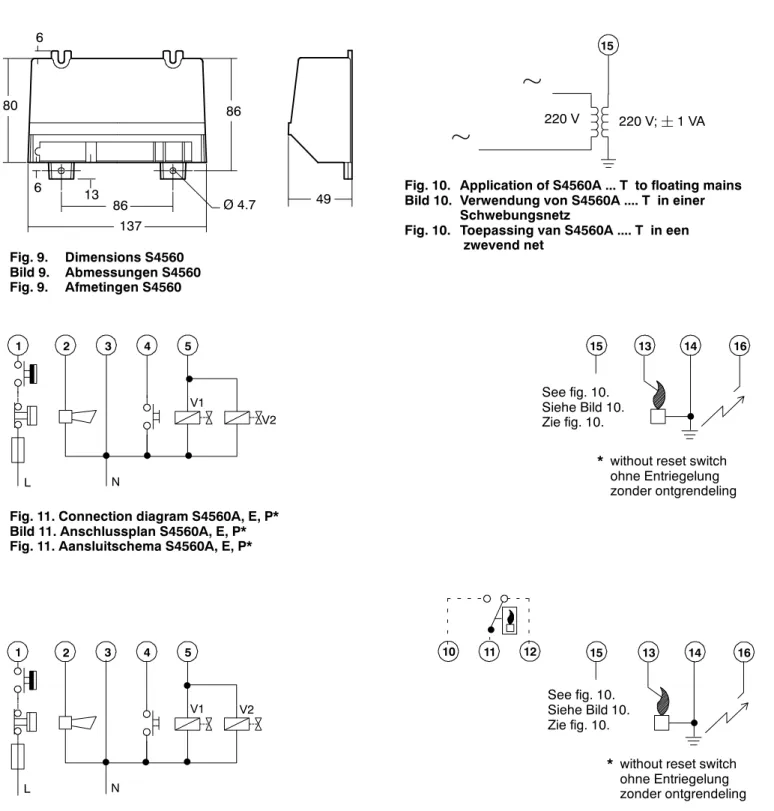
Ø 4.7 49 86 80 6 86 137 13 6 Fig. 9. Dimensions S4560 Bild 9. Abmessungen S4560 Fig. 9. Afmetingen S4560
µ
15Fig. 10. Application of S4560A ... T to floating mains Bild 10. Verwendung von S4560A .... T in einer
Schwebungsnetz
Fig. 10. Toepassing van S4560A .... T in een zwevend net 220 V
µ
220 V;¦1 VA¯
¯
¯
¯
V1 V2 1 2 3 4 5 13 14 16 L N* without reset switch ohne Entriegelung zonder ontgrendeling 15 See fig. 10. Siehe Bild 10. Zie fig. 10.
¯
Fig. 11. Connection diagram S4560A, E, P* Bild 11. Anschlussplan S4560A, E, P* Fig. 11. Aansluitschema S4560A, E, P*
¯
¯
¯
¯
V1 V2 1 2 3 4 5 13 14 16 L N 10 11 12¯
* without reset switch ohne Entriegelung zonder ontgrendeling 15 See fig. 10. Siehe Bild 10. Zie fig. 10.
¯
Fig. 12. Connection diagram S4560B, Q* with potential free flame relay connection Bild 12. Anschlussplan S4560B, Q* mit spannungsfreiem Flammenrelais Anschluss Fig. 12. Aansluitschema S4560B, Q* met spanningsvrij vlamrelais aansluiting
¯
¯
¯
¯
¯
V1 V2 1 2 3 4 5 13 14 16 L NO 10 11 12* without reset switch ohne Entriegelung zonder ontgrendeling 15 See fig. 10. Siehe Bild 10. Zie fig. 10. C NC L N
Fig. 13. Connection diagram S4560B, Q* Bild 13. Anschlussplan S4560B, Q* Fig. 13. Aansluitschema S4560B, Q*
¯
¯
¯
¯
¯
V1 V2 1 2 3 4 5 13 14 L NO 10 11 12* without reset switch ohne Entriegelung zonder ontgrendeling 15 See fig. 10. Siehe Bild 10. Zie fig. 10. C NC L N
Fig. 14. Connection diagram S4560B, Q* with external ignition transformer Bild 14. Anschlussplan S4560B, Q* mit externer Zündeinheit
Fig. 14. Aansluitschema S4560B, Q* met externe ontsteektransformator
¯
Fig. 15. Connection diagram S4560B with LPG valve, GPS, TTB switch and external ignition transformer Bild 15. Anschlussplan S4560B mit LPG Ventil, Gasdruckwächter, Rauchgasüberwachungsschalter und
externer Zündeinheit
Fig. 15. Aansluitschema S4560B met LPG gasklep, gasdruk schakelaar, TTB schakelaar en externe
¯
¯
¯
¯
V1 1 2 3 4 5 7 9 13 14 L N 10 12¯
LPG¯
V2 TTB GPS¯
** TTB switch must be a non volatile type and must be reset by manual operation.
* Der Rauchgasüberwachungsschalter muss der Type “non volatile” sein und soll nur Rückstellbar sein durch Betätigung der Rückstelltaste.
¯
¯
¯
¯
¯
¯
¯
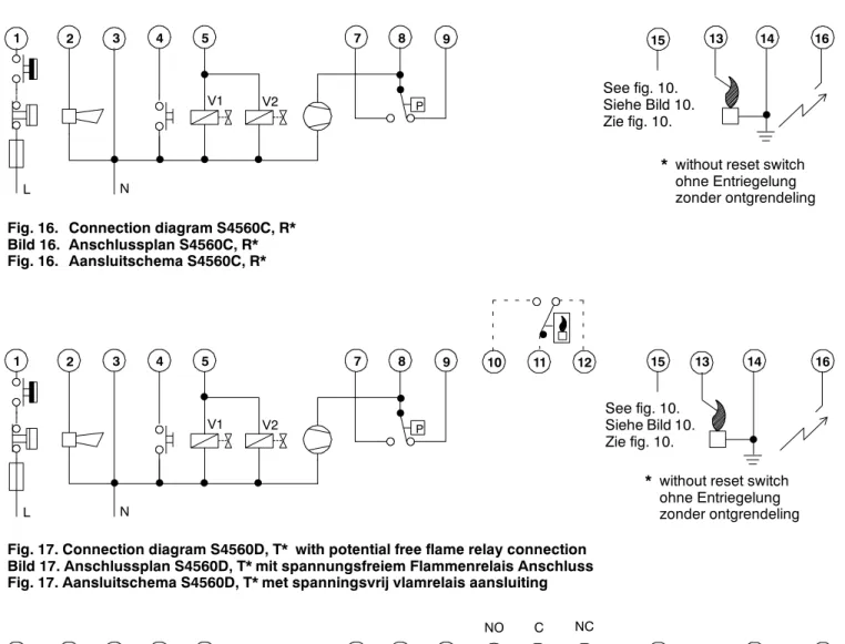
V1 V2 1 2 3 4 5 7 8 9 13 14 16 P L N* without reset switch ohne Entriegelung zonder ontgrendeling 15 See fig. 10. Siehe Bild 10. Zie fig. 10.
¯
Fig. 16. Connection diagram S4560C, R* Bild 16. Anschlussplan S4560C, R* Fig. 16. Aansluitschema S4560C, R*
Fig. 17. Connection diagram S4560D, T* with potential free flame relay connection Bild 17. Anschlussplan S4560D, T* mit spannungsfreiem Flammenrelais Anschluss Fig. 17. Aansluitschema S4560D, T* met spanningsvrij vlamrelais aansluiting
¯
¯
¯
¯
¯
¯
¯
V1 V2 1 2 3 4 5 7 8 9 13 14 16 P L N 10 11 12¯
* without reset switch ohne Entriegelung zonder ontgrendeling 15 See fig. 10. Siehe Bild 10. Zie fig. 10.
¯
Fig. 18. Connection diagram S4560D, T* Bild 18. Anschlussplan S4560D, T* Fig. 18. Aansluitschema S4560D, T*
¯
¯
¯
¯
¯
¯
¯
V1 V2 1 2 3 4 5 7 8 9 13 14 16 P L N 10 12* without reset switch ohne Entriegelung zonder ontgrendeling 15 See fig. 10. Siehe Bild 10. Zie fig. 10.
¯
NO C NC 11Fig. 19. Connection diagram S4560D, T* with external ignition transformer Bild 19. Anschlussplan S4560D, T* mit externer Zündeinheit
Fig. 19. Aansluitschema S4560D, T* met externe ontsteektransformer
¯
¯
¯
¯
¯
¯
¯
V1 V2 1 2 3 4 5 7 8 9 13 14 P L N 10 12* without reset switch ohne Entriegelung zonder ontgrendeling