Development of wear resistant metal matrix composite coatings based on laser surfacing engineering technique / Moinuddin Mohammed Quazi
194
0
0
Full text
(2) a. DEVELOPMENT OF WEAR RESISTANT METAL MATRIX COMPOSITE COATINGS BASED ON LASER SURFACING ENGINEERING TECHNIQUE. M. al. ay. MOINUDDIN MOHAMMED QUAZI. rs. ity. of. THESIS SUBMITTED IN FULFILMENT OF THE REQUIREMENTS FOR THE DEGREE OF DOCTOR OF PHILOSOPHY. U ni. ve. FACULTY OF ENGINEERING UNIVERSITY OF MALAYA KUALA LUMPUR. 2017.
(3) UNIVERSITY OF MALAYA ORIGINAL LITERARY WORK DECLARATION Name of Candidate: MOINUDDIN MOHAMMED QUAZI. Registration/Matric No: KHA140059 Name of Degree: DOCTOR OF PHILOSOPHY. a. Title of Thesis: DEVELOPMENT OF WEAR RESISTANT METAL MATRIX. ay. COMPOSITE COATINGS BASED ON LASER SURFACING ENGINEERING. al. TECHNIQUE. M. Field of Study: ADVANCE MATERIALS / NANO MATERIALS I do solemnly and sincerely declare that:. U. ni. ve r. si. ty. of. (1) I am the sole author/writer of this Work; (2) This Work is original; (3) Any use of any work in which copyright exists was done by way of fair dealing and for permitted purposes and any excerpt or extract from, or reference to or reproduction of any copyright work has been disclosed expressly and sufficiently and the title of the Work and its authorship have been acknowledged in this Work; (4) I do not have any actual knowledge nor do I ought reasonably to know that the making of this work constitutes an infringement of any copyright work; (5) I hereby assign all and every rights in the copyright to this Work to the University of Malaya (“UM”), who henceforth shall be owner of the copyright in this Work and that any reproduction or use in any form or by any means whatsoever is prohibited without the written consent of UM having been first had and obtained; (6) I am fully aware that if in the course of making this Work I have infringed any copyright whether intentionally or otherwise, I may be subject to legal action or any other action as may be determined by UM. Candidate’s Signature. Date:. Subscribed and solemnly declared before, Witness’s Signature. Date:. Name: Designation:. ii.
(4) ABSTRACT. Laser based additive manufacturing technology (LAM) comprising of Laser composite surfacing (LCS) technique has emerged as an alternative photon driven manufacturing technology for the fabrication of hybrid metal matrix composite coatings to enhance the mechanical and tribological properties of critical machinery components. To meet the. a. application needs, instead of bulk material processing, surface coatings are rendered far. ay. more suitable and are often utilized in form of Hybrid metal matric composite coatings (HMMC). These coatings have great potential in the fabrication and regeneration of. al. automotive, aerospace, defense and manufacturing components as protective hard. M. facing self-lubricating wear resistant composite coating. Under the category of lightweight metals, self-lubricating coatings have eluded aluminium alloys and. of. researchers have not realized the potential of optimization techniques for the laser. ty. processing parameters. This may dramatically increase the friction coefficient and wear. si. rates of critical sliding components and the full potential of improvement in mechanical and surface properties are not realized. The present work explores the possibility to. ve r. utilize several wear resistant metal matrixes composite (MMC) and hybrid (HMMC) coatings with the assimilation of various solid lubricants in these coatings blends to. ni. investigate their tribo-mechanical performance. In the first phase fabrication,. U. characterization and optimization of Ni-WC based wear resistant MMC coatings was deposited on aluminium alloy AA5083. To achieve laser composite surfacing, an analysis on optimization of laser processing parameters was made, in order to improve the tribo-mechanical properties of aluminium alloy. To carry out the investigation, Taguchi optimization method using standard orthogonal array of L16 (34) was employed. Thereafter, the results were analyzed using signal to noise (S/N) ratio response analysis and Pareto analysis of variance (ANOVA). Finally, confirmation tests with the best. iii.
(5) parameter combinations obtained in the optimization process were made to demonstrate the progress made. Results showed that the surface hardness (953 H v) and roughness (0.81m) of coated AA5083 samples were enhanced by 9.27%, and 13.14% respectively. Tribological behavior of LCS samples was investigated using ball-on-plate tribometer against a counter-body of hardened and tempered 440c bearing steel. It was revealed that the wear of the Ni-WC coated samples improved to around 2.5 times. For. a. lower applied loads, coating exhibited abrasive wear mode and a reduction in plastic. ay. deformation. In the second phase, solid lubricant coating comprising of lamellar graphite and TiO2 was employed to fabricate Ni-WC based HMMC coatings on Al-Si. al. hypereutectic piston alloy. The concentrations of both solid lubricants were varied in. M. concentration of 5, 10, and 15 wt. % to identify their optimum concentration. Results indicated that the addition of graphite and TiO2 to fabricate HMMC was beneficial in. of. reducing friction and wear of Ni-WC MMC coating. Furthermore, the hardness of both. ty. coatings was improved. The wear mechanism of MMC coating was transformed into. U. ni. ve r. si. mild abrasive and adhesive after the addition of both solid lubricants.. iv.
(6) ABSTRAK. Berasaskan teknologi pembuatan bahan tambahan Laser (LAM) yang terdiri daripada Laser permukaan komposit teknik (LCS) telah muncul sebagai foton didorong teknologi pembuatan alternatif untuk fabrikasi logam hibrid lapisan matriks komposit untuk meningkatkan sifat-sifat mekanikal dan tribological komponen jentera kritikal. Bagi memenuhi keperluan permohonan, daripada pemprosesan bahan pukal, lapisan. a. permukaan diberikan jauh lebih sesuai dan sering digunakan dalam bentuk logam. ay. salutan komposit matrik Hibrid (HMMC). lapisan ini mempunyai potensi yang besar. al. dalam pembuatan dan pertumbuhan semula automotif, aeroangkasa, pertahanan dan. M. pembuatan komponen yang melindungi sukar dihadapi salutan komposit tahan Haus diri pelincir. Di bawah kategori logam ringan, lapisan diri pelincir tidak terurai aloi. of. aluminium dan penyelidik tidak menyedari potensi teknik pengoptimuman untuk parameter pemprosesan laser. Ini secara mendadak boleh meningkatkan pekali geseran. ty. dan memakai kadar komponen gelongsor kritikal dan sepenuhnya potensi peningkatan. si. dalam sifat-sifat mekanik dan permukaan tidak direalisasikan. Kajian yang meneroka. ve r. kemungkinan untuk menggunakan beberapa memakai matriks logam tahan komposit (MMC) dan hibrid (HMMC) lapisan dengan asimilasi pelbagai pelincir pepejal dalam. ni. lapisan ini menggabungkan untuk menyiasat prestasi tribo-mekanikal mereka. Dalam. U. fasa pertama fabrikasi, pencirian dan pengoptimuman Ni-WC memakai berdasarkan lapisan MMC tahan didepositkan pada aloi aluminium AA5083. Untuk mencapai laser komposit permukaan, analisis pengoptimuman parameter pemprosesan laser telah dibuat, untuk meningkatkan sifat-sifat tribo-mekanikal aloi aluminium. Menjalankan siasatan, kaedah pengoptimuman Taguchi menggunakan pelbagai ortogon taraf L16 (34) telah digunakan. Selepas itu, keputusan telah dianalisis dengan menggunakan isyarat-hingar analisis sambutan (S/N) nisbah dan analisis Pareto varians (ANOVA). Akhirnya, ujian pengesahan dengan kombinasi parameter yang terbaik diperolehi dalam. v.
(7) proses pengoptimuman telah dibuat untuk menunjukkan kemajuan yang dibuat. Hasil kajian menunjukkan bahawa kekerasan permukaan (953 Hv) dan kekasaran (0.81μm) sampel AA5083 bersalut telah dipertingkatkan masing-masing sebanyak 9.27%, dan 13.14%. tingkah laku Tribological sampel LCS disiasat menggunakan tribometer bolaon-plat terhadap balas badan keras dan marah 440C galas keluli. Ia telah mendedahkan bahawa memakai sampel Ni-WC bersalut meningkat kepada kira-kira 2.5 kali. Untuk. a. beban yang lebih rendah gunaan, salutan dipamerkan mod memakai kasar dan. ay. pengurangan dalam ubah bentuk plastik. Dalam fasa kedua, pelincir pepejal yang terdiri daripada grafit lamela dan TiO2 telah bekerja untuk mereka-reka Ni-WC lapisan. al. HMMC berdasarkan Al-Si aloi omboh hipereutektik. Kepekatan kedua-dua pelincir. M. pepejal telah diubah dalam kepekatan 5, 10, dan 15 wt. % Untuk mengenalpasti kepekatan optimum. Keputusan inducated bahawa penambahan grafit dan TiO2 untuk. of. mereka-reka HMMC adalah benifical dalam mengurangkan geseran dan haus lapisan. ty. MMC Ni-WC. Tambahan pula, kekerasan kedua-dua lapisan telah bertambah baik.. si. Mekanisme memakai lapisan MMC telah berubah menjadi sederhana kasar dan pelekat. U. ni. ve r. selepas penambahan kedua-dua pelincir pepejal.. vi.
(8) ACKNOWLEDGEMENTS. My father Syed Munawar Uddin Quazi is a lovely person and it is because of him that I have inherited such abilities in completing my PhD. My mother Shahina Tabassum is a woman whom I owe my life to. My son, Faseeh Uddin Mohammed Quazi who remained a source of inspiration to me, throughout the PhD tenure. I would like to express my gratitude to Dr. Mohammad Abul Fazal, Professor Dr. A.S.M.A Haseeb and. a. Dr. Farazila Binti Yusof who have been my supervisor as well as the mentor of the. ay. thesis. My earnest thanks are given to my former mentor Dr. Erfan and Dr. A. D Sarhan.. al. I wish to extend my warmest thanks to all my colleagues in the Department of. M. Mechanical Engineering and the laboratories that have made this work successful. Special mentions of Puan Hartini from surface engineering laboratory who helped me. of. immensely. Moreover, I am thankful to Faculty of Dentistry and Faculty of Science for. ty. providing with characterization resources.. si. Last but not least all my teachers of Faculty of Engineering who have supported me in a. ve r. way such that I was able to produce this research. Additionally, I am grateful to my friends Mr. Arslan Ahmad, Dr. Tipu sultan, Dr. Faisal Siddiqui and Mr. Ghulam. ni. Mujtaba Shaikh for their moral support. I would like to acknowledge the financial. U. support provided by the Research Grant of University Malay’s, Grant No CG061-2013 and PRO13A-13AET. My lovely father Syed Munawar Uddin Quazi also gave financial support to me. At last, I shall highly acknowledge the role of friends and family for their continuous commitment and rigorous help which are my only source of strength and vitality.. Moinuddin Mohammed Quazi May 2016. vii.
(9) TABLE OF CONTENTS. ABSTRACT ....................................................................................................................iii ABSTRAK ....................................................................................................................... v ACKNOWLEDGEMENTS .......................................................................................... vii TABLE OF CONTENTS .............................................................................................viii LIST OF FIGURES .....................................................................................................xiii. a. LIST OF TABLES .....................................................................................................xviii. ay. LIST OF ABBREVIATIONS ..................................................................................... xix CHAPTER 1: INTRODUCTION .................................................................................. 1 Background .............................................................................................................. 1. 1.2. Problem Statement ................................................................................................... 5. 1.3. Research Objectives ................................................................................................. 6. 1.4. Framework of Thesis................................................................................................ 6. of. M. al. 1.1. Introduction to Lasers .............................................................................................. 8. si. 2.1. ty. CHAPTER 2: LITERATURE REVIEW ...................................................................... 8. Construction of Lasers ................................................................................... 10. 2.1.2. Classification of lasers ................................................................................... 12. ve r. 2.1.1. Lasers in Coatings Technology .............................................................................. 13. ni. 2.2. Laser Surface Modification of Aluminium Alloys ................................................ 15. U. 2.3. 2.3.1. High Power Lasers suitable for surface modification .................................... 18. 2.3.2. Laser Surface Melting (LSM) ........................................................................ 20. 2.3.3. Laser Surface Alloying (LSA) ....................................................................... 22. 2.3.3.1. LSA with addition of Nickel (Ni) and Ni based Alloys .................... 23. 2.3.3.2. Addition of Chromium (Cr) and Cr based Surface Alloys ............... 25. 2.3.3.3. Addition of Copper (Cu) and Cu based Surface Alloys .................... 25. 2.3.3.4. Addition of Molybdenum (Mo) and Mo based Surface Alloy.......... 25. 2.3.3.5. Addition of Other Surface Alloying Systems ................................... 26. 2.3.4. Laser Surface Cladding (LSC) ....................................................................... 27. viii.
(10) 2.3.4.1. Cladding of Metallic/Alloy Layer ..................................................... 28. 2.3.4.2. Cladding of Ceramic and Composite Layer ...................................... 29. 2.3.5. 2.4. Laser Composite Surfacing (LCS) ................................................................. 34. 2.3.5.1. Addition of Micron Sized Particles ................................................... 35. 2.3.5.2. Addition of Nanometer sized particles .............................................. 37. Laser coatings incorporating solid-lubricants ........................................................ 38 Friction Reduction Mechanism ...................................................................... 39. 2.4.2. Classification of Solid-Lubricants.................................................................. 39. 2.4.3. Lamellar based solids ..................................................................................... 40. a. 2.4.1. Addition of Graphite ......................................................................... 47. 2.4.3.2. Addition of Molybdenum di sulphide (MoS2) .................................. 49. 2.4.3.3. Addition of Tungsten di sulphide (WS2)........................................... 51. 2.4.3.4. Addition of hexagonal boron nitride (hBN) ...................................... 52. al. Halides and metal oxides based materials ...................................................... 53. M. 2.4.4. ay. 2.4.3.1. Addition of calcium di fluoride (CaF2) ............................................. 59. 2.4.4.2. Addition of Titanium di oxide (TiO2) ............................................... 59. of. 2.4.4.1. Applications of laser based self-lubricating composite coatings ........................... 60. 2.6. Statistical experimental design techniques............................................................. 61. ty. 2.5. Taguchi Design of Experiment ...................................................................... 62. 2.6.2. Analysis of variance Pareto (ANOVA) technique ......................................... 64. ve r. si. 2.6.1. 2.7. Summary and conclusion ....................................................................................... 65. ni. CHAPTER 3: MATERIALS AND EXPERIMENTAL METHODS ....................... 67 Substrate Materials ................................................................................................. 67. U. 3.1. 3.1.1. AA5083-O Aluminium Wrought Alloy ......................................................... 67. 3.1.2. Al-17Si Hypereutectic Cast alloy................................................................... 67. 3.2. Coating Materials ................................................................................................... 68. 3.2.1. MMC coating powders ................................................................................... 68. 3.2.1.1. Nickel as Matrix phase ...................................................................... 68. 3.2.1.2. WC as Particulate phase .................................................................... 69. 3.2.2. HMMC coating powders ................................................................................ 69. 3.2.2.1. Graphite as solid lubricant phase ...................................................... 70. ix.
(11) 3.2.2.2 3.3. TiO2 as solid lubricant phase ............................................................ 70. Experimental Methods ........................................................................................... 71. 3.3.1. Substrate pre-processing ................................................................................ 72. 3.3.2. Powder Pre-placement ................................................................................... 72. 3.3.2.1. MMC coating composition ............................................................... 73. 3.3.2.2. HMMC coating composition ............................................................ 73. 3.3.3. Laser processing parameters for MMC coating ................................ 74. 3.3.3.2. Laser processing parameters for HMMC coatings............................ 75. a. 3.3.3.1. 3.4.1. ay. Characterization and microstructural analysis ....................................................... 75 Scanning Electron Microscopy (SEM) .......................................................... 76 Beam-Specimen Interactions ............................................................ 76. 3.4.1.2. Equipment Details ............................................................................. 76. 3.4.2. al. 3.4.1.1. M. 3.4. Laser Surface Processing ............................................................................... 74. Atomic Force Microscopy (AFM) ................................................................. 77. 3.4.2.1. Fundamentals ................................................................................... 78. 3.4.3.2. Equipment Details ............................................................................. 79. ty. 3.4.3.1. Surface analysis ...................................................................................................... 79 Vickers Micro-hardness ................................................................................. 79. ve r. 3.5.1. si. 3.5. Xray-Diffraction (XRD)................................................................................. 78. of. 3.4.3. Equipment Details ............................................................................. 77. 3.5.2. Tribological Testing ............................................................................................... 80. ni. 3.6. 3D surface scan, surface profilometry and roughness Testing....................... 80. Tribological testing parameters for AA5083 and MMC coating ................... 82. 3.6.2. Tribological testing parameters for Al-17Si and HMMC coating ................. 82. U. 3.6.1. 3.7. Comparative evaluations between MMC and HMMC coatings ............................ 82. CHAPTER 4: RESULTS AND DISCUSSION .......................................................... 84 4.1. Optimization of Ni-WC MMC coating .................................................................. 84. 4.1.1. Design of experiment ..................................................................................... 84. 4.1.2. Taguchi method: analysis of the signal-to-noise ratio ................................... 85. 4.1.3. Influence of processing parameters on hardness and roughness .................... 89. 4.1.4. Pareto-ANOVA Analysis ............................................................................... 90. x.
(12) 4.2. Microstructure and Phase identification................................................................. 94. 4.2.1. Microstructure and Phase identification of Ni-WC coating ........................... 94. 4.2.2. Microstructure of substrate Al-17Si hypereutectic alloy ............................. 100. 4.2.3. HMMC coating deposited on Al-17Si ......................................................... 101. 4.2.4. Phase identification of Ni-WC-Graphite coating ......................................... 103. 4.2.5. Phase identification of Ni-WC-TiO2 coating ............................................... 104. Hardness of MMC and HMMC coatings ............................................................. 106. 4.4. Tribological properties of MMC coating ............................................................. 107. a. 4.3. Wear and friction coefficient of AA5083 and Ni-WC coating .................... 108. 4.4.2. Characterization of worn surface and debris ................................................ 112. 4.4.3. Atomic force microscopy of worn scars ...................................................... 117. al. Tribological properties of HMMC coatings ......................................................... 118. M. 4.5. ay. 4.4.1. Wear and friction coefficient of Al-17Si substrate, Ni-WC-Graphite and NiWC-TiO2 coating ..................................................................................... 118. 4.5.2. Wear characteristics of substrate Al-17Si alloy ........................................... 122. of. 4.5.1. Characterization of worn surfaces ................................................... 123. 4.5.2.2. Counter-body wear and debris analysis .......................................... 124. Wear characteristics of Ni-WC-Graphite coating ........................................ 126. 4.5.3.1. Counter-body wear and debris analysis .......................................... 129. ve r. 4.5.3.2. Characterization of worn surface .................................................... 126. si. 4.5.3. ty. 4.5.2.1. 4.5.4. Wear characteristics of Ni-WC-TiO2 coating .............................................. 134 Characterization of worn surface .................................................... 134. 4.5.4.2. Counter-body wear and debris analysis .......................................... 137. ni. 4.5.4.1. Comparative Evaluations ..................................................................................... 140. U. 4.6. 4.6.1. 3D Surface scans and roughness profilometry of worn scars for AA5083, Al-17Si, MMC and HMMC coatings ...................................................... 140. 4.6.2. Comparative evaluation of wear mechanism for AA5083, Al-17Si, MMC and HMMC coatings ................................................................................ 145. CHAPTER 5: CONCLUSION AND FUTURE WORK ......................................... 149 5.1. Conclusion ........................................................................................................... 149. 5.2. Future Work ......................................................................................................... 149. REFERENCES ............................................................................................................ 152. xi.
(13) LIST OF PUBLICATIONS........................................................................................ 170. U. ni. ve r. si. ty. of. M. al. ay. a. AWARDS ..................................................................................................................... 173. xii.
(14) LIST OF FIGURES. Figure 2.1: The power density range for various laser-material processing and joining (Majumdar & Manna, 2003) ............................................................................................. 9 Figure 2.2: Application of laser in various manufacturing processes (Majumdar & Manna, 2003) .................................................................................................................. 10 Figure 2.3: The structure of typical laser equipment (Majumdar & Manna, 2003) ........ 10. a. Figure 2.4: (a) Schematics of the LSC process (b) an Ishikawa diagram of LSC (Mondal et al., 2011)...................................................................................................................... 15. ay. Figure 2.5: Energy absorption of the laser beam for pure aluminum, AA5456 and AA6063 (%). ................................................................................................................... 17. M. al. Figure 2.6: Spectral reflectance of aluminum and various other metals. (Reprinted with permission from Elsevier, License no: 3575990476470) (L. Li, 2000) .......................... 19. of. Figure 2.7: Schematics of LSM I – in the area of the laser scanned filet and II – the area between laser-scanned filets. (Reprinted with permission from Elsevier, License no: 3575150149465) (Pariona et al., 2013) ........................................................................... 21. ty. Figure 2.8: Vickers hardness of various Al alloys after LSM treatment. ....................... 21. ve r. si. Figure 2.9: Schematics of LSA: (a) direct injection of powder and (b) preplaced powder technique. (Reprinted with minor modification taking permission from Springer, License no: 3575790741638) (Singh & Harimkar, 2012) .............................................. 22 Figure 2.10: Vickers hardness of various Al alloys after LSA treatment. ...................... 23. U. ni. Figure 2.11: Effect of powder flow rate on: (a) surface hardness and (b) mass loss of Ni and Ni-Ti-C alloying as obtained by pin-on-disk wear testing. (Reprinted with permission from Elsevier, License no: 3575180604467) (D’Amato et al., 2014a) ........ 24 Figure 2.12: Evolution of microstructure of Al–Mo surface alloy remelted (a-d) under increased traverse speed. (Reprinted with permission from Elsevier, License no: 3575180909391) (Amélia Almeida et al., 2006) ............................................................ 26 Figure 2.13: Vickers hardness of different laser claddings on aluminum alloys ............ 28 Figure 2.14: LSC application in a) valve seat repair and b) piston ring groove repair. (Reprinted with permission from Springer, License no: 3575181179845) (Arnold & Volz, 1999)...................................................................................................................... 29. xiii.
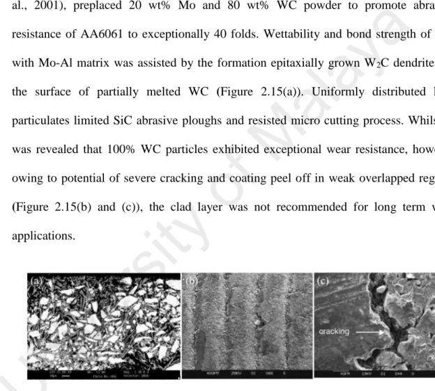
(15) Figure 2.15: SEM image of a) cross sectional microstructure 20 wt% Mo and 80 wt% WC laser clad, (b) 100 wt% WC cladded wear track and (c) magnified view of cracks on wear track. (Reprinted with permission from Elsevier, License no: 3575820558488) (Chong et al., 2001) ......................................................................................................... 33 Figure 2.16: (a) Axicon and Plano-convex lens configuration to produce ring beam profile and (b) energy intensity distribution of ring beams in comparison to conventional Gaussian beam (Reprinted with permission from Elsevier, License no: 3575190366744) (Blum & Molian, 2014) .................................................................................................. 37. ay. a. Figure 2.17: Schematics of adhesive contact between two surfaces and adhesion leading to the generation of transfer film which is detached from the softer solid and adhered to the harder solid. ............................................................................................................... 39. al. Figure 2.18: The Vickers hardness of various claddings with and without lamellar based solids lubricant ................................................................................................................ 41. M. Figure 2.19: Friction coefficient enhancement due to addition of lamellar based solids lubricant........................................................................................................................... 41. of. Figure 2.20: Micro hardness of various samples cladded with additions of solid lubricant........................................................................................................................... 54. ty. Figure 2.21: Reduction in friction coefficient of various samples cladded with additions of solid lubricant ............................................................................................................. 54. ve r. si. Figure 3.1: Schematics of (a) sandblasting of substrate; (b) Powder pre-placement; (c) laser processing 3D- view; (d) cross-sectional view ....................................................... 71 Figure 3.2: Schematic diagram of the ball on plate tribometer ...................................... 81. ni. Figure 3.3: Block diagram depicting the key steps involved in the fabrication and characterization of the MMC and HMMC coatings ....................................................... 83. U. Figure 4.1: The signal to noise (S/N) response graph for (a) surface hardness, (b) surface roughness ........................................................................................................................ 88 Figure 4.2: The XRD pattern of laser composite surfaced AA5083 with Ni-WC coating ......................................................................................................................................... 94 Figure 4.3: Cross-sectional optical micrograph of single scanned track ........................ 95 Figure 4.4: SEM overview of overlay of Ni-WC coating .............................................. 95 Figure 4.5: SEM cross sectional images along with EDS spot scanning for (a) top section of Ni-WC coating with a magnified view of Al3Ni dendritic structure, (b) middle section containing dendrites of Al3Ni2 and AlNi ............................................................ 97. xiv.
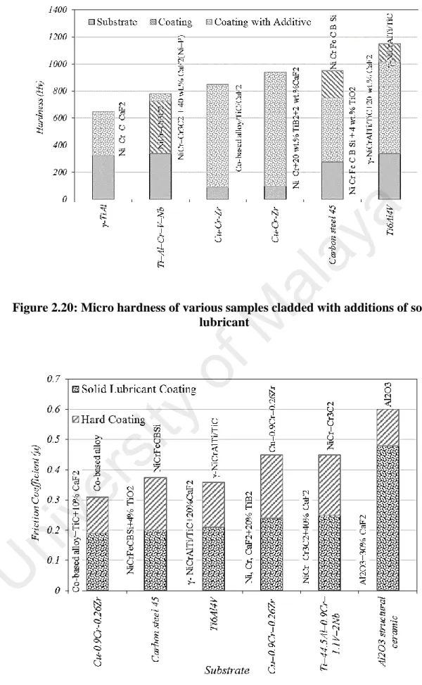
(16) Figure 4.6: EDS area scanning for (a) top section of Ni-WC coating with, (b) middle section ............................................................................................................................. 99 Figure 4.7: Optical micrograph of Al-17 wt. % hypereutectic piston alloy at 20X magnification................................................................................................................. 100 Figure 4.8: SEM and EDS area mapping of Al-Si hypereutectic alloy ........................ 100 Figure 4.9: SEM cross-sectional view of laser composite surfacing of Ni-WC-graphite based composite coating deposited on Al-17Si Substrate ............................................ 101. a. Figure 4.10: SEM cross-sectional view of substrate/coating interface of Ni-WC-graphite based composite coating deposited on Al-1Si Substrate .............................................. 102. ay. Figure 4.11: SEM overview of overlay of Ni-WC-graphite coating overlays .............. 102. al. Figure 4.12: The X-ray diffraction spectrum for Ni-WC coating with graphite content (a) 5 wt. % (b) 10 wt. % and (c) 15 wt. % .................................................................... 103. M. Figure 4.13: The X-ray diffraction spectrum for Ni-WC coating with TiO2 content (a) 5 wt. % (b) 10 wt. % and (c) 15 wt. % ............................................................................. 105. of. Figure 4.14: The surface hardness profiles for Ni-WC coating with graphite and TiO2 content ........................................................................................................................... 107. si. ty. Figure 4.15: The friction coefficient of (a) AA5083 and (b) Ni-WC coating as a function of cumulative time for 10, 20, 30 and 40 N load .......................................................... 109. ve r. Figure 4.16: (a) Steady state friction coefficient of AA5083 and Ni-WC coating under various applied loads, (b) Wear response of AA5083 and laser treated Ni-WC coating. ....................................................................................................................................... 111. U. ni. Figure 4.17: Scanning electron micrograph of worn surfaces for (a) AA5083 and (b) NiWC coating along with their EDS spectra of (c) area E and (d) area F ........................ 114 Figure 4.18: SEM images of debris for (a) AA5083 and (b) Ni-WC coating along with optical micrograph of 440c steel counter-body for (c) AA5083 and (d) Ni-WC coating ....................................................................................................................................... 115 Figure 4.19: Atomic force microscopy (AFM) images of worn scar morphology of (a) AA5083; (b) Ni-WC coating......................................................................................... 118 Figure 4.20: The friction coefficient of Al-17%Si and coatings with graphite and TiO2 additives ........................................................................................................................ 119. xv.
(17) Figure 4.21: (a) Wear response of Al-17Si and laser treated Ni-WC coating with additives (b) Steady state friction coefficient of Al-17Si and laser treated Ni-WC coating with additives ................................................................................................... 121 Figure 4.22: Scanning electron micrograph of worn surfaces for Al-Si alloy (a) Debrisscar interface, (b) and (c) at 0.5K and 1.0K magnification along with corresponding (d) EDX elemental mapping of O, Al, Si, Ni and Fe elements .......................................... 124. a. Figure 4.23: (a) EDX mapping of images for debris of Al-17%Si debris elemental mapping, (b) and (c) SEM image of debris at 0.5k and 2.0k magnification, (d) EDX elemental mapping of Al, O, Si and Fe and Fe element debris, (e) and (f) optical micrograph of counter body scar at distinctive magnifications .................................... 125. al. ay. Figure 4.24: SEM image of coating wear with their magnified views for (a), (b) 5 wt. % graphite (d), (e) 10 wt. % graphite, (g), (h) 15 wt. % graphite, along with their corresponding EDX carbon element mapping in (c), (f) and (i). .................................. 127. M. Figure 4.25: EDS spot scanning spectrums on worn scars of (a) Ni-WC-5 wt. % Graphite, (b) Ni-WC-10 wt. % Graphite and (c) Ni-WC-15 wt. % Graphite ............... 129. of. Figure 4.26: Optical micrographic images of counter-body worn tracks at lower and higher magnification for (a), (b) 5 wt. % graphite (c), (d) 10 wt. % graphite, (e), (f) 15 wt. % graphite ............................................................................................................... 130. si. ty. Figure 4.27: SEM images of counter-body worn debris at lower and higher magnification for (a), (b) 5 wt. % graphite (c), (d) 10 wt. % graphite, (e), (f) 15 wt. % graphite.......................................................................................................................... 133. ve r. Figure 4.28: SEM image of coating with their magnified view for (a), (b) 5 wt. % TiO 2 (d), (e) 10 wt. % TiO2, (g), (h) 15 wt. % TiO2, along with their corresponding EDX titanium element mapping in (c), (f) and (i). ................................................................. 135. U. ni. Figure 4.29: EDS spot scanning spectrums on worn scars of (a) Ni-WC-5 wt. % TiO2, (b) Ni-WC-10 wt. % TiO2 and (c) Ni-WC-15 wt. % TiO2 ............................................ 137 Figure 4.30: Optical micrographic images of counter-body worn tracks at lower and higher magnification views for (a), (b) 5 wt. % TiO2 (d), (e) 10 wt. % TiO2, (g), (h) 15 wt. % TiO2..................................................................................................................... 138 Figure 4.31: SEM images of counter-body worn debris at lower and higher magnification for (a), (b) 5 wt. % TiO2 (c), (d) 10 wt. % TiO2, (e), (f) 15 wt. % TiO2 140 Figure 4.32: 3D surface scans for (a) AA5083, (b) Al-17Si (c) Ni-WC, (d) Ni-WC-15 wt. % Graphite (e) Ni-WC-15 wt. % TiO2 .................................................................... 141 Figure 4.33: Surface roughness (Ra) of worn scars in nano-meters for substrates and coatings. ........................................................................................................................ 142 xvi.
(18) U. ni. ve r. si. ty. of. M. al. ay. a. Figure 4.34: Surface profilometry scans for (a) AA5083, (b) Al-17Si (c) Ni-WC, (d) NiWC-15 wt. % Graphite (e) Ni-WC-15 wt. % TiO2. ...................................................... 144. xvii.
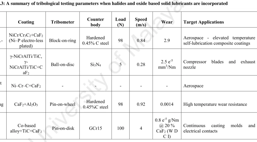
(19) LIST OF TABLES. Table 2.1: List of various Al substrate laser surface cladding with different processing parameters. ...................................................................................................................... 31 Table 2.2: A summary of tribological testing parameters when lamellar based solid lubricants are incorporated .............................................................................................. 44 Table 2.3: A summary of tribological testing parameters when halides and oxide based solid lubricants are incorporated ..................................................................................... 55. ay. a. Table 2.4: A summary of LSC and tribological testing parameters with the addition of combination of solid lubricants and soft metals .............................................................. 57 Table 3.1: A summary of all material properties of all materials utilized ...................... 70. M. al. Table 3.2: Laser processing parameters and their levels employed for the fabrication of MMC Ni-WC coating ..................................................................................................... 75 Table 4.1: Laser processing parameters and their levels employed in this experiment .. 84. of. Table 4.2: The measure values of surface hardness and roughness with their corresponding calculated S/N ratios................................................................................ 86. si. ty. Table 4.3: The (S/N) response values of laser processed AA5083 for surface hardness and for surface roughness................................................................................................ 87. ve r. Table 4.4: Pareto-ANOVA analysis for surface hardness .............................................. 92 Table 4.5: Pareto-ANOVA analysis for surface roughness ............................................ 93. ni. Table 4.6: The EDS chemical composition (at. %) by spot scan along with corresponding XRD phases detected. ............................................................................. 97. U. Table 4.7: A summary of Tribo-mecahnical properties of substrates and coatings ...... 145 Table 4.8: Comparative analyses of wear mechanisms for substrates, MMC and HMMC coatings based on worn scar, debris and counter-body morphology ............................ 147. xviii.
(20) LIST OF ABBREVIATIONS. Arabic Symbols. Frequency. HZ. P. Normal load. N. Fk. Kinetic Frictional Force. N. H. Hardness. MPa. Hv. Vicker's hardness. Ra. Arithmetic average of roughness. m. Rmax. Maximum surface roughness. m. s. Sliding distance. v. Sliding velocity. V. Volume. t. Sliding time. ρ. ay. al. M. m/s mm3 min. ty. of. m. Kinetic Friction. -. Density. Kg.m-3. ve r. µk. MPa. si. Greek Symbols. a. f. ni. Abbreviations. Light amplification by spontaneous emission of radiation. Ni. Nickel. WC. Tungsten Carbide. LSA. Laser Surface Alloying. LSM. Laser surface Melting. LSC. Laser surface cladding. LCS. Laser composite Surfacing. U. LASER. xix.
(21) Abbreviations. Aluminum Association. COF. Coefficient of Friction. CTE. Coefficient of Thermal Expansion. SEM. Scanning Electron Microscopy. FESEM. Field emission scanning electron microscopy. EDX. Energy dispersive X-Ray spectroscopy. OM. Optical Microscopy. AFM. Atomic Force Microscopy. XRD. X-Ray diffraction. AISI. American Iron and Steel Institute. ASM. American Society of Materials. MMC. Metal Matrix Composite. HMMC. Hybrid Metal Matrix Composite. ay. al. M. of. ty si. Aluminum matrix composite. U. ni. ve r. AMC. a. AA. xx.
(22) CHAPTER 1: INTRODUCTION 1.1. Background. Aluminum (Al) is the first most abundant metal and the third most abundant element (after oxygen and silicon) making about 8-wt% of earth crust. Al having a low density of 2.7 g/cm3 is currently replacing dense ferrous materials due to relentless pressure in. a. the second half of the 20th century to curb fossil fuels consumption. Aluminum metal. ay. has excellent properties such as good machinability, ductility, workability, weld-ability and ease of recyclability (Dursun & Soutis, 2014). Introducing alloying elements in Al. al. matrix such as, chromium, copper, lithium, magnesium, molybdenum, nickel, silicon. M. and zinc intensifies strength, cast-ability and heat resistance. However, Al alloys under specific conditions remains unsuitable for various structural and machinery applications. of. owing to their insufficient resistance to erosion, fatigue and tribochemical wear (Kalita,. ty. 2011; Richman & McNaughton, 1990). These properties are associated with near. si. surface regions. Thus without degrading the critical properties of the bulk phase, the. ve r. modification of composition and microstructure through localized processing or surface engineering serves as a viable solution for widening the application of aluminum alloys.. ni. Surface technology processes such as ion implantation especially with nitrogen (Figueroa et al., 2012; Oñate et al., 1998), cyro-milling (Tang et al., 2008), plasma. U. nitriding (F. Y. Zhang & Yan, 2014) and plasma sintering (Bathula et al., 2012) have been carried out to enhance mechanical properties of Al alloys. In addition, numerous other surface engineering techniques such as anodizing (Sarhan et al., 2013), physical vapor deposition (PVD) Ezazi et al. (2014a), chemical vapor deposition (CVD) (Uhlmann et al., 2014), thermal spraying (Picas et al., 2005) and sol gel coatings (Sepeur & Frenzer, 2014) have been employed to produce tens of micro and nanometer coatings. Nevertheless, owing to the difference in film-to-substrate elastic modulus, the. 1.
(23) thin hardened layer is prone to cracking on softer Al substrates, thereby resulting in higher specific wear. Furthermore, poor film-to substrate adhesion leads to adhesion, cohesion and delamination failure in a tribological contact. The aforementioned arguments convincingly demonstrate that a thicker, harder layer will entail far superior tribological characteristics. Laser surface engineering (LSE) is a non-contact material processing technique and has. a. manifested possibilities for novel material research. Although LSE techniques have. ay. been around for the last 35 years (Zhong & Liu, 2010), but the research interest has. al. increased since the past decade (Dubourg & Archambeault, 2008). LSE introduces laser. M. controlled melting in the presence of particulate embedding and composition modifying film to furnish a precise balance of prerequisite properties. With lasers, novel. of. microstructures can be developed due to rapid solidification and incorporation of higher concentration of key elements (Singh & Harimkar, 2012). The coatings developed by. ty. conventional means are incapable of generating such microstructures since extended. si. solid solutions or metastable phases are mainly characterized by rapid solidification. ve r. rates. This localized processing technique allows the fabrication of materials made from a combination of transition metal nitrides, oxides, carbides and borides and incorporates. ni. higher metallurgical bond strength owing to laser’s high coherence, directionality and. U. high energy density (Pawlowski, 1999). The higher bond strength eradicates the possibilities of film-to-substrate delamination failure and reduction in tribological performance due to the presence of interfacial defects (Biswas, 2006). Since, wear, friction, and lubrication of material systems are one the most vital characteristics arousing the attention of almost all mechanical engineers in the field of surface engineering. These properties are of utmost importance when determining the tribological characteristics of critical sliding components. With the development of. 2.
(24) modern mechanical systems in aerospace, manufacturing and food industries, various components are now operating under severe conditions. Their working conditions may encompass excessive temperature (at 1000°C or above), high stress, fluid contamination, vacuum and corrosive or leakage prone environment. In such situations, the use of conventional or even advanced synthetic lubricants is compromised. Moreover, they cannot be used because of the difficulty in sealing, applying,. a. transporting and other factors. For instance, there are various components employed in. ay. the nuclear energy and aviation industries that operate under high-temperature. al. tribological load such as steam and gas power plant turbines, compressor blades (high. M. pressure and temperature), cylinder liners, sidewall seals, exhaust valves and exhaust components, nuclear valves, piping, adiabatic engine bearings etc. (Kathuria, 2000;. of. Miyoshi, 2007; Sexton et al., 2002). Also, there are numerous applications where the presence of lubricants is undesirable, impractical or is forbidden owing to the risk of. ty. contamination (food industries). Hence, under the given circumstances, liquid lubricant. ve r. friction.. si. ceases to perform its function and an alternate solution is required in reducing wear and. ni. The use of solid lubricant in composite coatings becomes a prerequisite in providing a low friction transfer film and protecting the opposing surface (Renevier et al., 2001). As. U. wear is dependent on surface properties, modifying the near surface regions only can enhance it. It is known that for tribological and solid lubricant coatings, the adhesion strength between the composite coating and substrates is the critical property. Thermal spraying and thin film techniques have a distinct interface between substrate and coating. The separated film-to-substrate interface inevitably leads to adhesion and delamination failure under wear (Leyland & Matthews, 2000). In LSC, there is a strong bond not only between the coating and substrate, but also between the matrix and. 3.
(25) reinforced phase. In particular, the underlying limitations of plasma-based composite coatings are problems of high porosity, poor inter-particle bonding, and extensive chemical inhomogeneity (Milella et al., 2001). It is worth mentioning that laser remelting can significantly enhance the quality of plasma spray coatings (K. L. Wang et al., 2000).. a. Laser composite surfacing (LCS) gives the advantage of fabricating in-situ composites. ay. by assisting the reactions between added pure elements or compounds (X.-B. Liu, Meng, et al., 2014). In this way, the interface is cleaner and the reinforcements are more. al. compatible with the matrix. LSC easily produces those distinctive phases, which are. M. sometimes difficult to obtain (Singh & Harimkar, 2012). In electro deposition, the. of. volume content of the self-lubricating particulate phase is difficult to control and particles can frequently agglomerate causing deterioration of composite properties. ty. (Praveen & Venkatesha, 2008). PTA surfacing technique limits the size of particulates. si. that can be added in the composite coating. LSC allows all types of particle size to be. ve r. added effectively in the coating. Furthermore, with the careful selection of processing parameters, it also eliminates particle agglomeration, offers sound fusion bonding with. ni. the surface, high deposition rates, fine quench microstructures comprising of near isotropic mechanical properties (Farahmand & Kovacevic, 2014; Weng et al., 2014).. U. Only a small percentage (<5%) of all surface engineering techniques are currently using laser based surface modifications (Singh & Harimkar, 2012). Limitations such as poor coupling of Al with laser, surface defects and poor uniformity are common in LSE of Al alloys. A defect free coating with higher hardness, wear and corrosion resistance is a general requirement regardless of modification technique utilized. Researchers have mainly focused on the optimization of the process parameters and design of cladding materials for achieving the desired properties.. 4.
(26) The tribological behavior of coating materials has been difficult to be comprehended just by taking into account the surface hardness only. As hard coatings do not sufficiently reduce friction coefficient and may not provide protection from the adjacent surface asperities (Holmberg, 1992). Whereas, in wear, rougher and hard particles from the sliding surface could be easily peeled off and thereby causing aggressive abrasive wear (Kato, 2000). Hence, it is thus quite important to adopt solid lubricant coatings. a. technology or additives that may reduce friction, wear, protect opposing surface and. ay. improve mechanical properties of coatings. Under the tribological load, the risk of. al. damage due to inaccessibility of the lubricant can be drastically reduced (Aouadi et al.,. M. 2014; Arslan et al., 2015) or eliminated by introducing solid lubricants (Bao et al.,. 1.2. Problem Statement. of. 2006) in the material system.. ty. Aluminium and its alloys are extremely difficult to be laser engineered owing to their. si. high reflectivity and poor energy absorption. Albeit being in the category of light. ve r. metals, these alloys gave great potential in replacing steel based heavy components, which are operating under tribological load. Hence, improving the mechanical and. ni. tribological properties of near-surface regions of Al-alloys will certainly boost their. U. usage in production and manufacturing of lighter components. Researchers have introduced the laser surface engineering technique but have failed to register lower friction coefficient on hard metal matrix based coatings. Hence, to produce harder and wear resistant coatings in addition to lower friction coefficient is the primary goal that is achievable through the addition of solid lubricants that have never been investigated on Al-alloys.. 5.
(27) 1.3. Research Objectives. The aim of the present work is to produce in a hybrid metal matrix composite coating (HMMC) layer in the order of micrometres to improve the surface hardness, wear resistance and friction coefficient of aluminium alloys. The composite layer will be expected to exhibit higher hardness and superior wear resistance when compared with Moreover, the effects of laser processing parameters and additives. a. the substrate.. ay. (graphite and TiO2) content on tribo-mechanical properties of Ni-WC MMC coating. al. will be examined.. M. The objectives of the present study are:. of. 1. To systematically optimize the coating deposition parameters such as laser power, scanning speed and defocus distance by Taguchi optimization and Pareto. ty. ANOVA method for the deposition of metal matrix composite (MMC) coatings.. si. 2. To investigate and characterize the effect of solid lubricant additives graphite. ve r. and TiO2 on friction and wear resistance of hybrid metal matrix composite (HMMC) coatings.. ni. 3. To identify and compare the change in wear mechanism of solid lubricant doped. U. HMMC and un-doped MMC coatings along with the substrates.. 1.4. Framework of Thesis. With the introduction of Chapter 1 wherein, the basis of the this thesis has been defined, it has been succeeded by Chapter 2. This chapter provides the theory and literature review to provide an overview of the recent developments in the field of Laser based surface modifications of Aluminium alloys. Further to this, as to how the application of additives such as solid-lubricants affect the tribo-mechanical performance. 6.
(28) of laser based metal matrix composite coatings is further discussed. A brief overview of the design of experiment through Taguchi technique has been summarized. Henceforth, a complete summary of the way forward that we obtain from the conducted literature review have been concisely pointed out.. Chapter 3, introduces the coating materials that have been utilized for the fabrication of. a. composite coatings. Their general mechanical properties have been summarized. This. ay. chapter further outlines the experimental fabrication techniques and the mechanical and tribological characterization procedures, utilized in the present research work. The. al. working principle of instruments that were used for the characterization of materials. M. have been briefly outlined.. of. Chapter 4, reports on the fabrication and characterization of MMC based composite coatings. This chapter presents a systematic study of the optimized combinatorial. ty. scheme to achieve surface hardness and roughness. Furthermore, the tribological. si. performance of MMC based on pin-on-plate tribometer has been investigated and. ve r. compared. Later on, in the end, a comparision between wear mechanisms of MMC and. ni. HMMC coatings are given.. Finally, the research work reported in this dissertation is summarized in Chapter 5. An. U. outlook on future research directions and the current gaps available in this field are also suggested in this section of the chapter.. 7.
(29) CHAPTER 2: LITERATURE REVIEW. This chapter details the literature review and theory related to the Laser surface modification of various aluminium alloys. Modern types of the MMC and HMMC coating used in the various aerospace, automotive and petroleum sectors have been presented along with a brief review of the physics underlying the operating mechanism. A brief overview of the laser processing parameters of the composite coatings and. a. modes/principles of laser operation have also been explained, with special focus on. ay. laser material interaction. The important aspects which are required to be considered. al. while selecting appropriate MMC coating materials and HMMC solid lubricants, have. Introduction to Lasers. of. 2.1. M. also been discussed.. Laser (Light Amplification by Stimulated Emission of Radiation) is the most influential. ty. invention of the 20th century (Zhong & Liu, 2010). The physics behind laser that is. si. based on quantum mechanics those are relatively complex and have been furnished in. ve r. Ref (Toyserkani et al., 2004). Laser is an electromagnetic radiation including a very broad range of wavelengths ranging from infrared up to ultraviolet, which is. ni. monochromatic and is thus able to propagate photons in a straight direction with. U. extremely high coherency and hence, it has been always the hub of attention due to its unexampled applicability in diverse applications. Lasers are capable of delivering very high (110 kW) to extremely low (some milliwatt) focused output power with a precise temporal (spatial) distribution in addition to very accurate spot dimension on almost any material or any kind of medium.. 8.
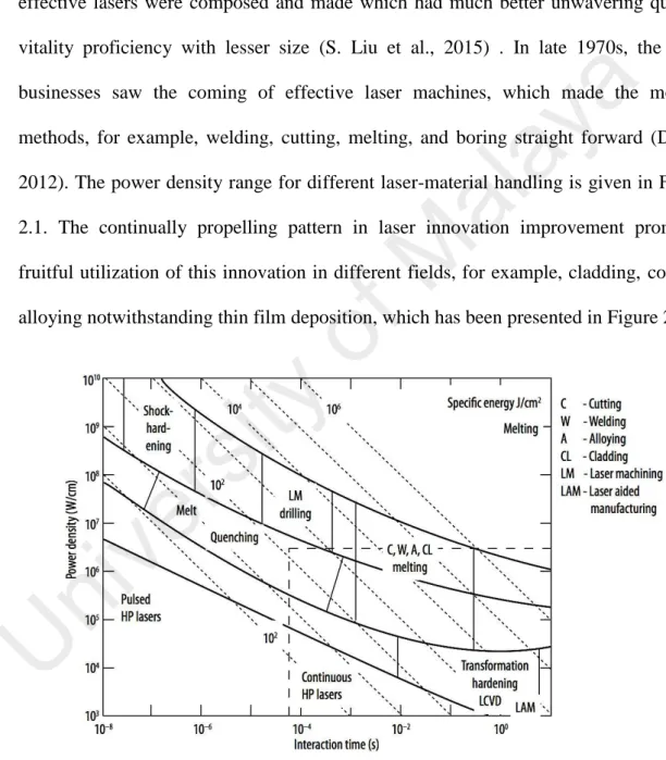
(30) Albert Einstein at initially developed the premise of laser hypothesis, which was along these lines affirmed by trial works of Ladenburg and Kopfermann (Milonni, 2015). Maiman was the creator of the principal laser gear with Ruby medium (Maiman, 2002). Later, an assortment of more current era laser are comprising of: CO2 gas laser, semiconductor, Nd:YAG, dye laser not withstanding numerous different sorts of more effective lasers were composed and made which had much better unwavering quality,. a. vitality proficiency with lesser size (S. Liu et al., 2015) . In late 1970s, the mass. ay. businesses saw the coming of effective laser machines, which made the modern methods, for example, welding, cutting, melting, and boring straight forward (Duley,. al. 2012). The power density range for different laser-material handling is given in Figure. M. 2.1. The continually propelling pattern in laser innovation improvement prompted fruitful utilization of this innovation in different fields, for example, cladding, coating,. U. ni. ve r. si. ty. of. alloying notwithstanding thin film deposition, which has been presented in Figure 2.2.. Figure 2.1: The power density range for various laser-material processing and joining (Majumdar & Manna, 2003). 9.
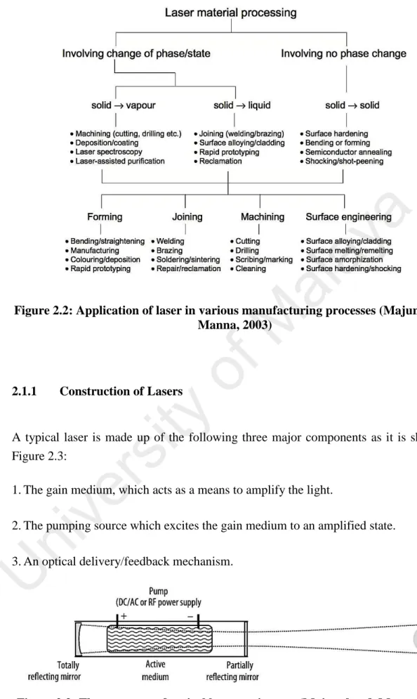
(31) a ay al. Construction of Lasers. ty. 2.1.1. of. M. Figure 2.2: Application of laser in various manufacturing processes (Majumdar & Manna, 2003). ve r. si. A typical laser is made up of the following three major components as it is shown in Figure 2.3: 1. The gain medium, which acts as a means to amplify the light.. ni. 2. The pumping source which excites the gain medium to an amplified state.. U. 3. An optical delivery/feedback mechanism.. Figure 2.3: The structure of typical laser equipment (Majumdar & Manna, 2003). 10.
(32) The further components in charge of cooling the mirrors, manipulating the targets in addition to guiding the laser beam are indispensable as well in order to assist the materials processing. The quantum mechanics principles state that when an external energy (stimulus) is supplied to the atom, the irradiated atom obtains an excited state (Silfvast, 2004). This excited atom can return spontaneously to the ground level (E1) from the higher energy level (E2) by emitting this difference in energy states as a. ay. 𝑣 = (𝐸2 − 𝐸1 )/ℎ. a. photon with a frequency equal to (ν):. (2.1). al. where "h" is the Planck’s constant. This phenomenon is known as spontaneous. M. emission. The photon emitted by spontaneous emission may in turn excite the secondary atom and stimulate it to emit a photon by de-exciting it to a lower energy. of. state. This phenomenon is called stimulated emission of radiation. The latter leads to. ty. generation of radiation, which is coherent and has the identical wavelength, phase and. si. polarization leading to generation of laser beam. Moreover, the optical resonator causes. ve r. the generated light parallel to its axis, to be reflected forth and back through the medium (Steen & Mazumder, 2010). If the light is in fact amplified due to the aforementioned process, and if the gain is equivalent to the round trip loss within the resonator, then. ni. both the resonator and amplifier are at the threshold for laser beam production. The. U. produced light in the excited resonator travelling parallel to its axis is amplified multiple times. A small portion of this light is merely released in each pass through a partially transparent mirror. The mirror system positioned in the resonator is a cavity consisted of a partially transmitting mirror at one side in addition to a completely reflective mirror on the other side. In laser equipment, this cavity is occupied by a pumping source and a medium. Despite the main responsibility of the optical resonator, it can also convert the laser radiation into a monochromatic and unidirectional beam.. 11.
(33) 2.1.2. Classification of lasers. Laser (Light Amplification by Stimulated Emission of Radiation) is the most influential invention of the 20th century. Based on the laser type and required wavelength, the medium of laser can be either in a gaseous, liquid or solid status. Various kinds of laser equipment are typically named according to the state or physical characteristics of their medium, upon which they can be classified into 4 major categories namely: solid state,. a. liquid, gas, in addition to semiconductor (glass) lasers. In the literature, mainly four. ay. kinds of high power lasers with optical wavelengths ranging from 248 nm to 10.6 µm are employed. These are CO2 lasers, neodymium-YAG (Nd: YAG) laser, high power. al. diode laser (HPDL) and fiber laser. The principal difference among these types of lasers. M. is the medium utilized in generating stimulated emissions. In CO2 lasers, light amplification is achieved by gas discharge which acts as the laser gain medium. Surface. of. processing by these lasers results in larger heat affected zones (HAZ). In Nd: YAG. ty. lasers, light amplification is achieved by using ionized neodymium (Nd) and crystal of. si. yttrium-aluminum-garnet (YAG). Nd is the light source and YAG is the host. In HPDL, diodes are used to amplify the light but they have poor beam qualities (L. Li, 2000). The. ve r. most common diode lasers are GaAs and AlxGa1-x. Lastly, in fiber lasers, the active gain medium is doped in optical fiber. Some of dopant materials are erbium (Er), dysprosium. ni. (Dy), neodymium (Nd), praseodymium (Pr), thulium (Tm) and ytterbium (Yb). As. U. compared to other laser types, fiber lasers produce excellent beam quality (beam parameter product) owing to use of smaller diameter fibers.. 12.
(34) 2.2. Lasers in Coatings Technology. Laser (Light Amplification by Stimulated Emission of Radiation) is the most influential invention of the 20th century (Zhong & Liu, 2010). LSC has been around for more than 35 years and has numerous advantages in the field of coatings technology (Dubourg & Archambeault, 2008). It offers the formation of unique microstructures and controlled localized heating which leads to smaller heat affected zone (HAZ) and induces lesser. a. thermal stresses (Watkins et al., 1997). In addition, the flexible cladding process, it. ay. offers sound fusion bonding with the surface, high deposition rates, and fine quench. al. microstructures with near isotropic mechanical properties (Weng et al., 2014). LSC process is often employed in repairing components and presents tremendous potential. M. for producing protective surfaces (Clare et al., 2012; Nowotny et al., 2015).. of. In laser surface cladding (LSC), an alloy or composite layer is fused onto the surface of. ty. a substrate with the assistance of a scanning laser beam Figure 2.4. The position of the. si. laser beam can be controlled with the help of scanning galvo mirror system, whereas a CNC based or a 3 stages motorized servo controller is utilized for controlling the axis of. ve r. the worktable. LSC process can be performed out in two ways. In one process, clad material is preplaced onto the substrate as a powder bed and the laser beam scans the. ni. powder bed with some degree of overlapping between each bead to form a surface.. U. Alternatively, the powders can be plasma sprayed or electroplated, or fed by wire followed by laser melting (Hung & Lin, 2004; Mendez et al., 2014). The material can also be added by a feeding wire system or else the powder mixture can be blown directly into the melt pool. Though the coating remains chemically different from the substrate, however in order to obtain higher metallurgical bond strength, some degree of reactions and mixing in the interfacial region becomes vital (Sexton et al., 2002). Owing to the application of a Gaussian laser beam energy mode, the thickness of the laser clad. 13.
(35) is higher at the centre than towards both sides of the track (Lei et al., 2015). Clad morphology can be segregated in three regions; the clad zone (CZ), the heat affected zone (HAZ) and the unaffected zone or substrate (Buchbinder et al., 2015). The microstructure as well as the composition of the coatings strongly depends on the degree of mixing, which is governed by convection, diffusion, and cooling rates during liquid-to-solid and solid-to-liquid phase transformation (Bergmann & Mordike, 1986;. a. Mondal et al., 2014). LSC requires irradiation of high energy density laser beam (102 –. ay. 104 W/mm2) on material surface within a very short interaction time (10-3 – 1 s). During LSC process, due to the application of extremely high power density, the melt pool. al. temperature can soar as high as 2000 °C (Elhadj et al., 2014). The sudden temperature. M. increase followed by abrupt cooling produces very high thermal gradients (Farahmand & Kovacevic, 2015). These higher cooling rates, up to 1011 K/s results in the formation. of. of hard phases, induces microstructural refinement and leads to solid solution. ty. strengthening (Draper & Poate, 1985a). Hence, the parameters controlling these. si. mechanisms are of paramount importance to the laser surface cladding process. Figure 2.4(b), the probable process control parameters on clad quality has been studied. ve r. (Mondal et al., 2011) and presented in the form of a cause–effect (Ishikawa) diagram. Clearly, the quality of LSC process greatly relies upon a variety of factors such as the. ni. laser power, traversing speed, powder feed and spot size etc. It is the combination of. U. some of these parameters that controls the solidification rate and subsequently results in grain refinement and formation of non-equilibrium phases in the cladding. Therefore, optimization of cladding process parameters is important aspect in-terms of coating quality.. 14.
(36) a ay al M of ty si ve r. ni. Figure 2.4: (a) Schematics of the LSC process (b) an Ishikawa diagram of LSC (Mondal et al., 2011). Laser Surface Modification of Aluminium Alloys. U. 2.3. Based on the interaction of materials with high speed photons, laser surface modifications can be classified into five major categories, which comprises of i) laser surface melting, ii) laser surface alloying, iii) laser composite surfacing, iv) laser surface cladding and v) laser shock peening. Laser based surface modifications either involves melting of the substrate with or without filler material except for shock peening. These processes necessitate the use of shielding gas to prevent oxidation, use of filler (except in laser surface melting) and crack stabilizers (during rapid. 15.
(37) solidification). The aforementioned processes have some merits and demerits and a suitable process should be approached depending on the properties desired. Treating Al alloys with laser possesses major constraints of lower melting point of aluminum and the poor absorption of electromagnetic radiation (7%) due to high density of free electrons present, which strongly relate to surface conditions (Touloukian & DeWitt, 1970). Absorptivity relies on band structure, the incident beam. a. wavelength, resistivity of metal and is also a function of the size and nature of the. ay. plasma present above the melt pool, concentration and phase of volatile alloying. al. elements in the metal and surface geometry (Miotello & Ossi, 2010). By modifying the surface geometry through increasing surface roughness, higher energy absorption can. M. be attained by virtue of earlier development of keyhole, which further contributes to. of. multiple reflections of the laser beam occurring in the cavities (Ang et al., 1997). Hence, prior to laser processing, sand blasting and rough grinding are performed in. ty. order to step-up incidence beam absorption and remove oxide scale. Dispersion of oxide. si. film is essential as it may lead to the formation of a molten pool of Al enclosed in a skin. ve r. of oxide, thereby promoting additional porosity. Figure 2.5 presents energy absorption of aluminum after various surface treatments signifying considerable increase in energy. ni. absorption in case of anodized and sand blasted specimens. Another alternative method. U. to improve laser energy absorption is coating graphite and black paint layer. Apart from enhanced energy absorption, the black paint layer vaporizes and thermal effects are reduced when the work piece surface is exposed to laser beam irradiation (Peyre & Fabbro, 1995). When laser beam scans across an absorber coating such as graphite on a metallic substrate, the absorber may evaporate or burn-off (Kek & Grum, 2010). However, unused graphite from the sample is easier to remove through acetone (Carey et al., 2007). The application of the absorber layer for optimal energy absorbance requires optimization of graphite coating thickness. Depending on the processing. 16.
(38) parameters, when graphite is added in excessive amounts, they may survive the laser radiation and can be incorporated in the coating as black particles (D’Amato et al.,. M. al. ay. a. 2014b).. ty. of. Figure 2.5: Energy absorption of the laser beam for pure aluminum, AA5456 and AA6063 (%).. si. Since aluminum is highly sensitive to lasing environment, hence various processing. ve r. factors should be taken into consideration. For example, aluminum is highly susceptible to hydrogen porosity and reacts easily with active gases like oxygen, water vapors in the. ni. atmosphere, adsorbed or present as hydrated oxide films (Hatch & Aluminum, 1984).. U. Therefore, careful selection of shielding gas is essential as it may preclude the formation of oxides that may aggravate metallurgical properties. The resulting plume dynamics due to inert environment provided, standoff distance and gas flow rates affect the quality of processing (Sibillano et al., 2006). Another issue in laser material processing is hot and cold cracking as a consequence of rapid solidification. Several researchers have prevented crack formation by employing an additional heat source to decrease thermal shock, while some have defocussed the laser beam (Brückner et al., 2007). In addition, flux and rare earth elements (RE) powders are utilized, which on 17.
(39) application of plasma are activated within the molten pool to restrict surface tension gradients (M. Wang et al., 2011). Similarly, crack stabilizers such as TiO2 (Ouyang et al., 2001) , CeO2 (Tao et al., 2000) and La2O3 (K. L. Wang et al., 2001) are added to stabilize microstructural evolution and prevent cracking. The extent of issues highlighted above is not complete but is an indication that considerable research is required for achieving defect free optimal coatings. High Power Lasers suitable for surface modification. a. 2.3.1. ay. In the literature, mainly four kinds of high power lasers with optical wavelengths. al. ranging from 248 nm to 10.6 µm are employed. These are CO2 lasers, neodymiumYAG (Nd: YAG) laser, high power diode laser (HPDL) and fiber laser. The principal. M. difference among these types of lasers is the medium utilized in generating stimulated. of. emissions. In CO2 lasers, light amplification is achieved by gas discharge which acts as the laser gain medium. Surface processing by these lasers results in larger heat affected. ty. zones (HAZ). In Nd: YAG lasers, light amplification is achieved by using ionized. si. neodymium (Nd) and crystal of yttrium-aluminum-garnet (YAG). Nd is the light source. ve r. and YAG is the host. In HPDL, diodes are used to amplify the light but they have poor beam qualities (L. Li, 2000). The most common diode lasers are GaAs and AlxGa1-x.. ni. Lastly, in fiber lasers, the active gain medium is doped in optical fiber. Some of dopant. U. materials are erbium (Er), dysprosium (Dy), neodymium (Nd), praseodymium (Pr), thulium (Tm) and ytterbium (Yb). As compared to other laser types, fiber lasers produce excellent beam quality (beam parameter product) owing to use of smaller diameter fibers (Richardson et al., 2010). Figure 2.6 presents the reflectance of processed aluminum under various radiation wavelengths (L. Li, 2000). Aluminum alloys are very difficult to be laser engineered successfully for the reason that high reflectivity results in poor coupling with the laser beam. Therefore, normal incidence is not employed in order to avoid the risk of beam 18.
(40) reflection, which may cause damage to collimator, mirrors and laser cavity (Dubourg, Pelletier, et al., 2002). Al alloys absorbs the laser energy more readily at shorter laser wavelength. At shorter wavelengths, the more energetic photons can be absorbed by a greater number of bound electrons resulting in higher absorption (Quintino et al., 2007). Clearly, the selection of laser is thus vital. Nd: YAG, HPDL and fiber lasers deliver far better coupling with aluminum than the CO2 laser (λ = 10.6 µm) due to the delivery of. a. shorter wavelengths of radiation (L. Li, 2000). It is worth mentioning that, diode. ay. pumped fiber lasers often termed as “greener lasers”, offer multiple advantages, including small beam focus diameters providing high power densities, precise fiber. U. ni. ve r. si. ty. of. M. al. delivery system, compact design, and robust installation.. Figure 2.6: Spectral reflectance of aluminum and various other metals. (Reprinted with permission from Elsevier, License no: 3575990476470) (L. Li, 2000). 19.
(41) 2.3.2. Laser Surface Melting (LSM). LSM requires irradiation of high energy density (102 – 104 W/mm2) on material within a very short interaction time (10-3 – 1 s) to cause localized melting at the surface. The schematic of LSM process is illustrated in Figure 2.7. Laser is scanned with a certain percentage of overlap to cover a larger area of surface with microstructural changes confined to near surface regions (Fariaut et al., 2006). The aspect ratio (depth to width. a. ratio) of melt region and grain size (dendrite arms spacing) is a function of beam. ay. diameter (irradiation area), scanning speed and applied power. Properties of LSM zone. al. are dependent on the substrate’s material composition, microstructure, laser power applied and spatial distribution of energy. The nature and extent of laser material. M. interaction is dictated by thermo physical properties like thermal conductivity,. of. temperature gradients, melting point, absorptivity and surface tension (Elhadj et al., 2014). In addition the amount of material hardening is dictated by the cooling rates at. ty. the liquid/solid boundary, the extension of the solid solubility and concentrations of. si. alloying elements present (Bergmann & Mordike, 1986). The Nd: YAG, CO2 and. ve r. Excimer lasers are generally utilized with an overlap of greater than 25% to achieve a maximum melt depth of around 2 mm. Greater overlap is required in order to obtain a. ni. surface with uniform melt depth. The resulting microstructure and surface properties in. U. the coincided region remain different. Transforming the shape of the incident beam profile can alter the laser beam energy distribution to attain preferred shapes of the molten pools, sustain microstructural and compositional uniformity (Fariaut et al., 2006). A fine-grained homogenous material is expected to resist micro fracturing in tribo-chemical wear (Allen & Ball, 1996). So far, Al alloys containing Fe, Si, Cu and Mg are found to exhibit higher micro-hardness after LSM treatment as showed in Figure 2.8.. 20.
(42) a ay. U. ni. ve r. si. ty. of. M. al. Figure 2.7: Schematics of LSM I – in the area of the laser scanned filet and II – the area between laser-scanned filets. (Reprinted with permission from Elsevier, License no: 3575150149465) (Pariona et al., 2013). Figure 2.8: Vickers hardness of various Al alloys after LSM treatment.. 21.
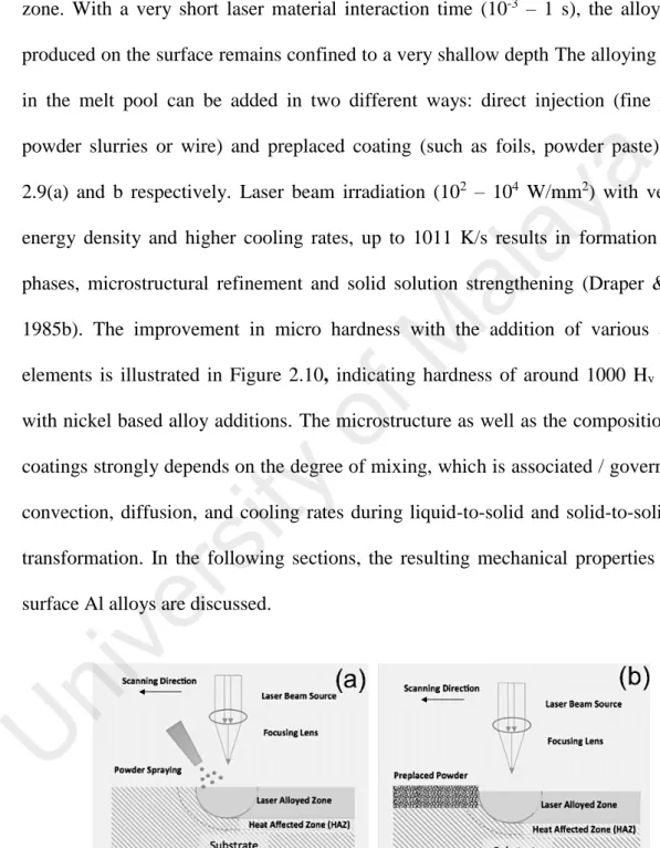
(43) 2.3.3. Laser Surface Alloying (LSA). LSA is a directed energy beam assisted surface alloying technique wherein various alloying elements can be inserted into the melt pool resulting in formation of alloyed zone. With a very short laser material interaction time (10-3 – 1 s), the alloyed zone produced on the surface remains confined to a very shallow depth The alloying element in the melt pool can be added in two different ways: direct injection (fine powder,. a. powder slurries or wire) and preplaced coating (such as foils, powder paste). Figure. ay. 2.9(a) and b respectively. Laser beam irradiation (102 – 104 W/mm2) with very high. al. energy density and higher cooling rates, up to 1011 K/s results in formation of hard phases, microstructural refinement and solid solution strengthening (Draper & Poate,. M. 1985b). The improvement in micro hardness with the addition of various alloying. of. elements is illustrated in Figure 2.10, indicating hardness of around 1000 Hv attained with nickel based alloy additions. The microstructure as well as the composition of the. ty. coatings strongly depends on the degree of mixing, which is associated / governed with. si. convection, diffusion, and cooling rates during liquid-to-solid and solid-to-solid phase. ve r. transformation. In the following sections, the resulting mechanical properties of laser. U. ni. surface Al alloys are discussed.. Figure 2.9: Schematics of LSA: (a) direct injection of powder and (b) preplaced powder technique. (Reprinted with minor modification taking permission from Springer, License no: 3575790741638) (Singh & Harimkar, 2012). 22.
Figure

+7


Outline
Related documents
Pertaining to the secondary hypothesis, part 1, whether citalopram administration could raise ACTH levels in both alcohol-dependent patients and controls, no significant
The purpose of this study was to use the SERVQUAL (Service Quality Instrument) to examine the perceptions of first-time enrolled students at University of North Carolina
After 72 hours of incubation, basal medium were centrifuged at 5000rpm for 20 min. The EPS was then precipitated from the supernatant by addition of equal amount of carbinol.
The inspector observed the administration of medication and found that safe medication management practices were not in place as medicines for a resident who refused to take them
Hindawi Publishing Corporation EURASIP Journal on Wireless Communications and Networking Volume 2008, Article ID 391025, 16 pages doi 10 1155/2008/391025 Research Article Analysis
A schematic view of the pathophysiology of secondary cerebral damage after traumatic brain injury (TBI) that supports the concept of optimizing cerebral blood flow, the delivery
Contributions by members of the TGFbeta superfamily to lens development DAVID BEEBE*,1, 2, CLAUDIA GARCIA1, XIAOHUI WANG1, RAMYA RAJAGOPAL1, MARY FELDMEIER1, JI YOUNG KIM1, ANNA
