TRANSACTION LEVEL MODELS’ STRUCTURING: FROM
IDIOMS TO TLM-2
SALAHEDDINE HAMZA SFAR, IMED BENNOUR, RACHED TOURKI
Laboratory of Electronic and Microelectronic, Faculty of Sciences at Monastir, Tunisia
Email: [email protected] , [email protected] , [email protected]
ABSTRACT
A system on chip (SoC) designing cost is not only dependent on the manufacturing process but also on the used design methodologies and tools. Transaction level modelling (TLM) has emerged as an efficient methodology of electronic system level (ESL) design, with an acceptable simulation speed and modelling accuracy. During the last decade, the research efforts were to define the various TLM abstraction levels, TLM taxonomies, and TLM programming languages. The result was the definition and the standardization of the SystemC language, the TLM-2 library and a set of coding styles. The further step toward an efficient TL modelling methodology consists in structuring the various TL models. This paper firstly reviews the most important steps in the evolution of the TLM methodology and secondly it presents an efficient structuring of the TL models based on TLM-2 library.
Keywords: Electronic System Level Design, SystemC, Transaction level modelling, architecture exploration, system in chip, network on chip.
1. INTRODUCTION
Due to the growing complexity of electronic systems, the use of a suitable design methodology can divide the design cost by 10 or 100 [1]. In [2], the authors assert that 80’s design methodologies called "capture and simulate" or those of 90’s called "describe then synthesize" are obsolete. The last decade marks the rise of the so-called
"specifies explores and refines" design
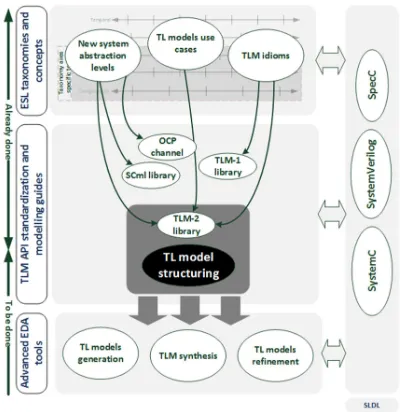
methodologies which fill the weaknesses of previous methodologies and bridge the widening gap between register transfer level (RTL) and system specifications. Over the years, a race is set to elevate the levels of abstraction and therefore, each methodology brings many novelties in terms of design flow and specification language. This give the birth to a new field of research called electronic system level (ESL) design [3-5]. It includes research works interested in resolving issues arising when we transform the system level model according to taxonomies illustrated in Figure 1.
New system-level design languages (SLDL), such as SystemC [6] and SystemVerilog [7], are the major success ingredient of ESL design methodologies [8]. As they are object-oriented (OO), the designer can isolate communication (i.e. interfaces) and each set of system’s functionalities in a separate class. The use of dynamic classes, the
concept of inheritance and parameterized
constructors allow designers to create flexible,
robust and reusable components. SystemC
presents, in addition to its compatibility with C++, means to describe a system at different levels of abstractions. It provides data types and hierarchical
structures to simulate synchronous and/or
asynchronous modules [9]. In other words, it allows describing semantics implemented in the various graduations of taxonomic axes of the Figure 1. Temporal Data Concurrency Communications Configurability G a te p ro p a g a tio n C y c le a c c u ra te S y st e m e v e n t C y c le a p p ro x im a te In s tr u ct io n c y
cle Toke
n c y cle P a rt ia l o rd e r B it F o rm a t V a lu e P ro p e rt y T o k e n S ig n a l P ip e lin e M u lt ith re a d P a ra lle l M u lt i A p p lic a tio n S e su e n tia l P o in t t o p o in t B u ffe re d L o w sp e e d B u s C o p ro ce ss o r M e m o ry H ig h sp e e d B u s N o n e F ix e d D e sig n C o n fig u ra b le P ro g ra m m a b le D y n a m ic
Taxonomy axes specific to ESL
High resolution
Low resolution
[image:2.595.89.289.478.684.2]
Transaction Level modelling (TLM) is among the most promising ESL methodology to handle the growing complexity [10]. The system designer focuses on the functionality of the communication between model elements without detailing its implementation when he writes a transaction level (TL) model. Such models focus on the exchanged data and the communication phases without giving importance to means used to accomplish the transfer of this data [11]. Verification, architecture exploration or early stage software development and validation are the main use cases of TL models [4], [12], [13] and [14]. Nevertheless, the high complexity of modern systems makes TL models very challenging to develop. They are tightly dependent on the system design taxonomy, the description languages, the developed TL idioms and the model’s use case. For that, TL models do not have a precise definition and several research groups such as in [15] and [16] are working to establish and enforce their standards. In 2011, the main update of the SystemC standard integrates TLM-2 library. It provides commonly used utilities to make easier the TL models writing. Nonetheless, standard establishment does not resolve everything; it is just the corner stone to pass to transaction-level synthesis and electronic design automation as next logical steps for the coming years. Before that, good practice in describing and simulating systems at transaction-level must be done and additional TLM guides need to be established.
Figure 2: TLM methodology - achievements and challenges
Figure 2 summarizes the achieved tasks and the
remained tasks toward a complete TLM
methodology. TL model structuring is one of the current challenging tasks. It has to define good practice and clear rules in TL model writing in order to allow a high degree of interoperability of the models from multiple designers and to accelerate the development of advanced EDA tools around TL models. In this paper, we trace the evolution of TLM’s concepts from idioms and basic abstraction levels to advanced application programming interface , then we propose a structuring solution for the most two dominating levels of TL models (transaction and transfer). At each abstraction level, we depict several methods involved in communication and specify theirs interactions. In addition, we take inventory of schemas to insert temporal constraints and we detail their implementations in the identified methods. The proposed solution targets the last SystemC standards.
The rest of this paper is organized as follows. Section 2 reviews the evolution and the basic concepts of TLM, which are transaction levels, TLM idioms, the TLM-2 library and coding styles. Section 3 and section 4 describes our proposal to structure respectively transaction and transfer models and details communication methods’ implementations. Section 5 discusses the extension of our solution to a network on chip (NoC) based communication modelling. Finally, section 6 concludes the paper.
2. TLM’S EVOLUTION
2.1 Basic transaction levels
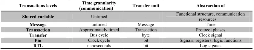
In a previous work [17], we contributed to identify six basic inter-modules transaction levels: shared variables, messages, transactions, transfers, pin and RTL. Each level marks a trade-off between relative simulation speed and communication details and accuracy and corresponds to a specific modelling scheme. The Table 1 summarizes their characteristics
Transaction and transfer models are inherent to the TLM. They help to fill the gap between a message level and Pin level. TLM describes the communication behavior of a module using function calls rather than driving physical signals. Modelling the communication with transactions and transfers is suitable for hardware blocks. Their meanings can be inferred by looking at bus cycle chronogram that shows arbitration transfer, addressing transfer and data exchange transfer. Both models are based on requests and responses that are transported by function calls. The designer adds, to the message data structure, attributes like address, data size and endianness to emphasize the system memory mapping. Compared to message model, functional entities become more structured and compartmentalized. The border between the communication part and the processing part in a
functional entity is more explicit. However, transaction and transfer models present some differences. In the transaction model, the communication protocol is sketchy and sums up to a possible delay between request and response,
added as a transaction attribute. The
communication part handles transactions on the fly, so there is no worry of transaction reorganization or buffering. While, transfer model divides communication protocol into non-repetitive phases.
The phase’s insertion induces two main
transformations in the model. Firstly, phases
impose additional synchronization points.
[image:3.595.86.511.355.440.2]Secondly, the designer should worry about transactions reorganization and buffering since the model’s components could handle transfers of different transactions.
Table 1: Inter-modules transaction levels
Transactions levels Time granularity
(communication) Transfer unit Abstraction of
Shared variable Untimed - Functional structure, communication
resources
Message untimed Message Time
Transaction Approximately timed Transaction Protocol phases
Transfer Bus cycle byte Clock signal
Pin Clock cycle bit Signals, registers, logic functions
RTL nanoseconds bit Logic gates
Finally, the pin level provides more details on the communication from the perspective of synchronization points. It links the phases of the communication with the activity of some pins of the communication medium. In a bus context, the address phase acts on address pins, the arbitration phase uses the control pins, etc. The only signal that may appear at pin level is the clock signal. When used, the phase duration is quantified in clock cycles. Unlike the transfer level, the number of phases is no more limited and belongs to the designer to determine their number. The phase sequence may include repetitions. These repetitions are very convenient to describe for example a bus burst mode. In this case, a unique address phase induce several payload exchange phases.
2.2 Proposals for transaction levels
Theoretically, the TLM methodology is
independent of the programming language used, but historically SystemC and SpecC [18] are the most system level description languages (SLDL) used to write transactional models. Several levels of abstraction have been proposed in the literature to describe the inter-module communication. In
Table 2 we summarize these levels according to, first, the used SLDL and, second, to the organization behind the work. Faced to the multitude the abstraction levels, a harmonization task is mandatory to achieve a high degree of interoperability and reuse of TL models.
In the interest of compatibility, it has released, at the end of 2008, a modelling kit using the OSCI TLM-2 interfaces. Its documentation introduces TL4 as a new level of abstraction for consistency purpose with the work of OSCI [35]. TL4 shares
the same interfaces used in TL3 models. These interfaces are then called OCP-IP TL3/TL4. In this way, TL4 corresponds exactly to OSCI-LT and TL3 is equivalent to OSCI-AT, but neither TL2 nor
[image:4.595.74.524.201.443.2]TL1 have equivalence in OSCI work.
Table 2: Transaction levels in literature
Organism Bibliographic
references Abstraction levels
S
p
ec
C
b
a
se
d University of
California Irvine [19) [20]
• Specification Model
• Processing Elements (PE) Assembling Model, or Architecture Model
• Bus Arbitration Model
• Time Accurate Communication Model
• Cycle Accurate Computation Model
• Implementation Model
S
y
st
e
m
C
b
a
se
d
Synopsys [21-25]
• Untimed Functional model
• Timed Functional Level
• Transaction Level Model or Bus Cycle Accurate Level
• Behavioral Hardware Model or Pin Accurate Level
• Register Transfer Model Open Core Protocol
International Partnership
(OCP-IP)
[26-29]
• Message level (TL3)
• Transaction level (TL2)
• Transfer level (TL1)
• RTL (TL0)
CoWare [30] [31]
• Functional View
• Programmers View
• Architects View
• Verification View Open SystemC
Initiative (OSCI)
[32] [33] • Loosely-Timed coding style (LT)
• Approximately-Timed coding style(AT)
OCP TL2
OCP TL3
Transaction level
Message Transaction Transfer Pin Registre transfer
Protocol Free Protocol refining
Untimed Cycle Timed
Approximate Timed
Communication synthesis Interface synthesis PE assembly
model
Specification model
Bus arb itration model
Time accurate communicati
on model / Cycle accurate computation
model
Implementation model
Time
Transaction level Time
Message Transaction Transfer Pin Registre transfer
Untimed function al model
Protocol Free Protocol refining Timed
function al model
TLM
Behavioral hardware model
RTL
OCP TL0
Untimed Cycle Timed
Approximate Timed
Communication synthesis Interface synthesis OCP TL1
Prog. View (PV)
Arch. View
(AV or PV+T)
Verification View (VV)
OSCI-AT
OSCI-LT
[image:4.595.89.519.481.634.2](a) SpecC based models (b) SystemC based models
Figure 3: Comparison of several transaction levels
2.3 TLM’s idioms
The most colloquial definition delimits a transaction as the exchange that takes place between two different points of a system, subsystem or module for a finite interval of time.
Transactions are based on idioms that are
considered basic concepts of the TLM
2.3.1 Core interfaces
Core interfaces, as discussed in [30], are atomic mechanisms essential to characterize transactional communication. They specify the control flow, the data flow, and the type of transaction. These core interfaces are put (), get () and transport ().
The “put ()” configuration corresponds to a component that sends a transaction to another component. We call initiator the component that initiates the transaction and target the component that receives it or simply the component that reacts to an initiator. Both the control flow and the data flow are from the initiator to the target. The “put ()” function is implemented using a pure virtual function. In object-oriented programming, it is a function with no implementation details and whose behaviour is overridden within an inheriting class by a function with the same signature. In our case, “put ()” is declared as a pure virtual function in the initiator and it is implemented in the target.
The “put ()” configuration corresponds to a component that sends a transaction to another component. We call initiator the component that initiates the transaction and target the component that receives it or simply the component that reacts to an initiator. Both the control flow and the data flow are from the initiator to the target. The “put ()” function is implemented using a pure virtual function. In object-oriented programming, it is a function with no implementation details and whose behaviour is overridden within an inheriting class by a function with the same signature. In our case, “put ()” is declared as a pure virtual function in the initiator and it is implemented in the target.
The “get ()” configuration is the complementary of “put ()”. In this case, the initiator receives transaction from the target: the control flow is from the initiator to the target, but the data flow takes the opposite direction. In this way “get ()” is declared in the initiator and implemented in the target. When using “get ()”, once the data is consumed, it is deleted within the producer. Another variant “peek ()” allows the consumer to read the data without erasing it in the producer.
Transport is a bidirectional interface. It generally follows the model of request-response pair, where each request is closely linked to a response. Generally, when using bidirectional interfaces, we use the terminology “master” and “slave” instead of “initiator” and “target”. The pair request-response fits perfectly when modelling memory access. When reading memory, the master asks slave for data at a specific address so the slave
responds by sending the corresponding data. The signature of “transport ()” can be seen as a fusion of the two unidirectional functions “put ()” and “get ()”and uses two arguments request and response.
2.3.2 Blocking and non-blocking communication
Interfaces mentioned above are blocking interfaces. This means that the entity that begins the transaction ceases all activities. The target or the slave takes the hand to perform some processing and returns with appropriate arguments. With blocking interfaces, there is no need to provide mechanisms to control the evolution of the transaction, because this latter, in some way, never fails: Receiving the response is a sign of the completion of the transaction. In addition, when using blocking interfaces, the designer must keep in mind that the request (i.e. the interface call) and the response (i.e. the interface return call) will occur in two different simulation moments.
TLM methodology proposes non-blocking variant of the interfaces mentioned above. The non-blocking semantic allows a return in the same delta cycle of the interface call. In a model using this type of interface, the two communicating entities no longer functioning alternately as in the blocking mode, but in parallel. Bodies of non-blocking interfaces are not too different from blocking counterparts; nevertheless, they return information about the evolution of the transaction. The consumer should examine this return value to determine whether the transaction is changing properly and consequently choose the next transaction step to proceed. In addition, buffers must be provided into both communicating entities to manage the transaction flow.
2.3.3 Interconnect component
As mentioned in the introduction, axis
“communication” is important in system
taxonomy. SystemC, as a SLDL, introduces in its second version the concept of communication channel. When writing high-level models in SystemC, modules communicate through ports that call interfaces that are implemented in channels. In addition, SystemC permit to describe hierarchical channel that includes processes and/or structured in sub-modules. It helps to develop an abstract model of a bus or a more complex communication structure.
the artifice “communication channel” but it also adds some improvements. For instance, the introduction of “export” in SystemC, since version 2.1, was a TLM requirement. It develops the idea that when using only ports, it is impossible to bind directly the communicating modules because the interfaces are implemented outside them and precisely in channels. As an export implements interfaces within the modules, a couple port - export allows a direct binding between two modules. However, a TL model may use bidirectional interfaces, where the requests and the responses take opposite paths. Therefore, the couple port - export becomes insufficient, especially when the communication is non-blocking. In [33], the authors introduce the object “socket”. It is composed of a port and an export. Directly binding two sockets of two modules in the same hierarchical level, is equivalent to bind a port of each module to the export of the other. This will allow to model transactional interconnections composed of two paths: a forward path and a backward path. The target’s socket implements the interface of the forward path and the initiator’s socket implements the interface of the backward path. Of course, in the case of a blocking communication the backward path becomes superfluous.
Consequently, a question that comes readily to mind: what about the communication channel in a TL interconnection? The answer follows from the system taxonomy. A transactional interconnection is usually more complex than a simple point-to-point connection and therefore it is more akin to a module rather than a channel that implements interfaces. This allows us to apply, to this so-called “channel module”, the same principle of the system taxonomy. Its communication part, i.e. core interfaces, is integrated in the communicating
modules and “channel module" integrates
functionality part. The “channel module" is commonly called in TLM: an interconnect component. This component acts as an initiator and a target at the same time. Even if it accesses to transactions, it is neither a producer nor a consumer. Definition of an address space, transformation of the address, definition of priority rules or transformation of transaction payload are common functionalities that can be integrated in a interconnect component. A bus, a bridge, an arbiter or a router can be considered as interconnect components. The separation of functionality and interfaces of a TLM interconnection makes the interconnect component interchangeable without making changes into the communicating modules.
2.3.4 The notion of time
The use of TL models is to bridge the gap between untimed functional models and cycle accurate models. Although, they offer a rough behaviour towards the time, they should be as faithful as possible to the behaviour of the system. It is obvious then that timing constraints insertion patterns are an important criterion to distinguish each TL model. The notion of time in a TL model is closely related to the synchronization points with the simulation kernel of the SLDL i.e. SystemC. To evolve correctly, the model must give the control to the simulation kernel to activate processes to clearly characterize the different relationships between them in order to describe the deterministic system behavior. In addition, synchronization points are important to control concurrent access to various shared variables, channels and memory to ensure the consistency of their contents.
The study of the simulation kernel, teaches us that the latter offers a repetitive execution of concurrent processes. Moreover, the order of execution of these processes at the first iteration is not predictable, but we know that it will keep this order in the following iterations. This non-determinism may give a non-compliant behavior compared to the functional specification of the system. Programmer View (PV) model, as the most abstract among TL models, does not give implementation details of the internal micro architecture. With such models, it is hard to predict the process activation and suspension moments or delays between synchronization points. Thereby, the designer must insert, time constraints to avoid this non-determinism or at least limit its influence. He use such constraints to define a partial order of events that govern the system behaviour in compliance with concurrent evolution of processes and cause-effect relationships that should exist between them. The causality brings an air of
determinism to the model, an essential
characteristic of real concurrent hardware
generates a huge and complex control flow and the model becomes slow to simulate.
Other types of temporal constraints may be added to a model of the type PV. They illustrate functional constraints such as UART transfer rate, a refresh rate of a display controller, or a delay required to perform any computation. Free from any micro-architecture, these, so-called, functional delays are just added to give more constraints on
process execution order. Unlike previous
constraints, they are inserted in the model as implicit synchronization points: the designer adds time annotations to TLM interface call. In models based on blocking interfaces, these annotations guarantee a certain orthogonality between these temporal constraints and the purely functional model. This has three advantages; firstly, these constraints can be easily removed to go back to a purely functional model; appreciated during the validation step. Secondly, these annotations can be easily enriched when the designer refines the model and substitute blocking interfaces with non-blocking ones. This is easily done without touching already validated functional parts of the models. Finally, these annotations have another beneficial effect on the model reuse. The designer can try several models of channel or interconnect component in a prelude of any advanced architectural exploration.
In any cases, implicit annotations can
materialize those advantages only if TLM interfaces are well specified and standardized.
When combined with a system design
methodology, they will be interpreted in various ways. In the context of a bottom-up methodology, the TL model is an assembly of existing components. In this case, the implicit annotations mimic the delays induced by these components. While in the context of a top-down methodology, these annotations are predictions for budgeting future refined implementations.
2.4 TLM-2 library and coding styles
Since the version 2.0, released in 2001, SystemC supports TLM methodology. It was limited to the use of channels, ports and interfaces. In parallel, a TLM working group was assigned the task of creating a TLM library to be included in the standard language. In 2005, this group released the version 1.0 of this library [36] which was succeeded in 2008 by the version 2. The latter was actually included in the SystemC standard in 2011. In [33], the authors explain that this version mainly targets the description of bus based systems. The
library defines three groups of interfaces: transport interface, direct memory interface (DMI) and debug interface. It also sets a specific data structure, named Generic Payload (GP), which is exchanged between the initiator(s) and target(s) in conjunction with these interfaces. In the interest of models’ interoperability, the library defines a communication protocol named Base Protocol (BP).
The Transport interfaces are the main interfaces provided by the TLM-2 library. These interfaces are provided in blocking and non-blocking forms. Both variants support time annotations and temporal decoupling. Temporal decoupling allows
a process to ignore certain number of
synchronization points, considered redundant, with the simulation kernel. However, juggling with synchronization points is not without risk. The designer must make the assumption that sampling variables too early or too late does not affect either model’s functionalities or model’s use case.
The blocking transport interface is called b_transport (). It is implemented in the target and it has no return value. It has two arguments: the transaction and the time annotation. The use of this interface is linked to a coding style called loosely timed (LT). In such kind of coding style, a transaction is linked to two timing points corresponding to the API call and its return. The return of b_transport () can be immediate or delayed with an explicit call of wait (). If the return is immediate, the initiator should check the time annotation argument, to solicit an eventually synchronization point.
Non-blocking transport interfaces are
target sends the response to the initiator and ends when the initiator actually receives it and becomes ready to receive the response of the next transaction. Thus, BEGIN_REQ and END_REQ mark the beginning and the end of the request.
BEGIN_RESP and END_RESP mark the
beginning and the end of the response.
BP defines the complete sequence of the
protocol as follows: (BEGIN_REQ END_REQ
BEGIN_RESP END_RESP). In addition to
this complete sequence, BP defines a multiple of valid phase sequences that can give the tempo to the transaction. Transaction phase may be changed by the return value or by the backward path. In fact, as shown in Figure 4, for each method call there are several possible call returns. We refer to each method call by Ai where i ∈ {1,2,3,4}. This
index marks the phase of the transaction after calling a TLM-2 non-blocking interface. The values 1, 2, 3 and 4 mark respectively BEGIN_REQ, END_REQ, BEGIN_RESP and END_RESP. We used the index 0 to mark the beginning of the transaction. The indexes 4 and 5 show in turn the end of a transaction. The latter
index indicates that the return value is
TLM_COMPLETED, so the phase argument is ignored. Rij refers to the call returns and i and j
refer respectively to call phase and return phase. In other words a call returns Rij may change the phase
of the transaction.
Initiator Target
nb_transport_fw(t,BEGIN_REQ,x) TLM_ACCEPTED nb_transport_fw(t,BEGIN_REQ,x)
Call
Return
TLM_UPDATED nb_transport_fw(t’,END_REQ,x+∆x)
TLM_COMPLETED nb_transport_fw(t’,-,x+∆x)
nb_transport_bw(t,END_REQ,x) TLM_ACCEPTED nb_transport_bw(t,END_REQ,y)
nb_transport_bw(t,BEGIN_RESP,x) TLM_ACCEPTED nb_transport_bw(t,BEGIN_RESP,x) TLM_UPDATED nb_transport_bw(t’,END_RESP,x+∆x) TLM_COMPLETED nb_transport_bw(t’,-,x+∆x) TLM_UPDATED nb_transport_fw(t’,BEGIN_RESP,x+∆x)
nb_transport_fw(t,END_RESP,x) TLM_ACCEPTED nb_transport_fw(t,END_RESP,x)
TLM_COMPLETED nb_transport_fw(t’,-,x+∆x)
Return
A 1
R11 T a rg e t la te n cy R e q u e st a cc e p t d e la y R12 R13 R15 Call
A 2 R22
Call
A 3 Return
R33
R34
R35
Call A 4
Return R44
[image:8.595.314.488.461.600.2]R45
Figure 4: Transaction evolution using non-blocking interfaces
3. STRUCTURING OF TRANSACTION
MODELS
As explained in previous section, the transaction model inaugurates the TL modelling. When SystemC is used, initiators and targets are defined in separate models communicating through the TLM-2 interfaces. In order to implement system
hierarchy we choose a structure using direct
instantiation of sub-modules and separate
compilation technique. We opted for this choice because separate compilation allows us to move the constructor in the implementation. Thus, we hide the complexity to the model’s user. In this way, this latter can have an idea about the hierarchy of the system by just browsing header files [9].
3.1 Separation of communication and functionality
In transaction model, separation of
communication and functionality is an obligation as explained in section 2.2. It must be implemented into both initiator and target modules. To do this, each functional unit is matched to a core and a wrapper: two sc_modules. The core implements the functionality and the wrapper allows the core to communicate with the other functional entities.
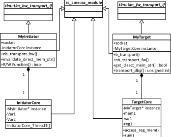
Figure 5 illustrates the static class diagram and
Code 1 shows extracts of several files
implementing an initiator side example of the static class diagram. The header file MyInitiatorCore.h defines the initiator’s core as a SimpleInitiatorCore class that inherits from the class sc_module. In the
core’s constructor, we implement
SimpleInitiatorCore_Thread (), it is the sc_thread responsible of carrying out some functionalities.
+nb_transport_bw() +invalidate_direct_mem_ptr() +R/W Function() : bool
MyInitiator +socket -InitiatorCore instance tlm::tlm_bw_transport_if sc_core::sc_module -InitiatorCore_Thread1() InitiatorCore -MyInitiator* instance -Var1 -Var2 1 1 +b_transport() +nb_transport_fw() +get_direct_mem_ptr() : bool +transport_dbg() : unsigned int
MyTarget +socket -MyTargetCore instance +access_reg_mem() +run() TargetCore -MyTarget* instance -mem1 -var1 -reg1 1 1 tlm::tlm_fw_transport_if
[image:8.595.92.284.474.626.2]12 13 14 15 16 17 18 19 . . 27 28 29 30 31 32 33 34 . . 45 46 47
#include "MyInitiatorCore.h" #include "Params.h"
class MyInitiator: public tlm::tlm_bw_transport_if<>,public sc_core::sc_module
{
public:
tlm::tlm_initiator_socket<> socket; . . .
SC_HAS_PROCESS(MyInitiator);
MyInitiator (
sc_core::sc_module_name name
);
. . .
private:
SimpleInitiatorCore m_core;
An extract of MyInitiator.h
18 19 20 21 22 23 24 25 26 27 28
MyInitiator::MyInitiator
(
sc_core::sc_module_name name
)
: sc_core::sc_module (name)
, socket ("socket")
,m_core ("SimpleInitiatorCore",this)
{
socket(*this);
}
An extract of MyInitiator.cpp
13 14 15 16 17 18 19 20 21 22 23 24 25 26 27 28 . . 39
#include "MyInitiator.h"
Class MyInitiator;
Class SimpleInitiatorCore: public sc_core::sc_module
{
public:
SC_HAS_PROCESS(SimpleInitiatorCore);
SimpleInitiatorCore (
sc_core::sc_module_name name,
MyInitiator* testbench
);
private:
. . .
MyInitiator* m_TestBench;
An extract of MyInitiatorCore.h
17 18 19 20 21 22 23 24 25 . .
SimpleInitiatorCore::SimpleInitiatorCore (
sc_core::sc_module_name name,
MyInitiator* testbench
)
: sc_core::sc_module (name)
, m_TestBench (testbench)
{ . . .
An extract of MyInitiatorCore.cpp
The extract of the header file MyInitiator.h shows that the wrapper is defined as a class named MyInitiator. This class inherits from both classes: sc_module and tlm::tlm_bw_transport_if<>. The second class is mandatory to set the public member “socket” as an initiator socket instance (line 19). MyInitiator also defines, as a private member, SimpleInitiatorCore instance (line 47). The wrapper constructor uses C++ syntax to bind a
pointer of a MyInitiator class to
SimpleInitiatorCore class. The pointer “this” is passed to the SimpleInitiatorCore class in the course of the core initialization. The pointer “this” represents the SimpleInitiatorCore class itself. It is
passed to the instance declaration for
SimpleInitiatorCore (line 25 in MyInitiator.cpp) and then to the core’s constructor (line 24 in MyInitiatorCore.h). Here, the pointer, passed from the wrapper, is bound to the pointer variable m_TestBench (line 24 in MyInitiatorCore.cpp).
Similarly, the target’s wrapper class inherits not
only the sc_module class but also
tlm::tlm_fw_transport_if<> class because it sets a member of the target type socket. This solution, which is quite complicated at first glance, allows us to define a straight line between functionalities and communication, an essential characteristic of a transaction model. In addition, it has a double
advantage. Firstly, communication and
functionalities are placed in two separate sc_module. Secondly, it does not involve additional SystemC objects to bind the two modules. We consider that adding objects such as ports or FIFOs might distort the model performances. By binding initiator and target wrapper’s pointer to their respective core, wrappers are the only SystemC modules visible at the top level of the model
3.2 Interaction between wrappers and cores
Splitting up a functional entity in a core-wrapper pair does not mean that its elements do not cooperate. In the initiator side, the core initiates cooperation with the wrapper. It asks, whenever is needed, services to the wrapper through functions
calls. We named these proposed functions R/W
functions. For example, to write data,
SimpleInitiatorCore_Thread () calls the R/W
function write_data () through the wrapper’s
pointer m_Initiator as follows:
m_Initiator->write_data(current_data,i);
R/W functions are implemented in initiator’s
wrappers and must perform the following steps:
1) Create a generic payload object;
2) set its attributes;
3) call the b_transport through a socket;
4) test response_status attribute and get
response informations;
5) and call wait() if delay parameter has
been updated by the target.
All R/W functions have a Boolean return that
the core uses to make decision about the next functionality to be executed.
In the target side, it is the wrapper that initiates cooperation with the core. The target‘s wrapper implements b_transport method which requests access to a resource in the core through a function
call. We named such called function Access
function. Typically an Access function performs
the following steps:
1) Decodes address attribute to identify
resource location.
2) Performs effectively the read or write
according to the command attribute.
3) Calls specific core functions
according to the context.
3.3 Autonomous modules
An autonomous module is a module with a target socket and an initiator socket. Hardware acceleration modules are the typical case of such module. The target socket serves for initialization and/or configuration purpose. During computation phase, Hardware acceleration module become autonomous since it can read or write data through its initiator socket.
+nb_transport_bw() +invalidate_direct_mem_ptr() +R/W Function() : bool +b_transport() +nb_transport_fw() +get_direct_mem_ptr() : bool +transport_dbg() : unsigned int
MyHWblock +i_socket +t_socket -HWblockCore instance
tlm::tlm_bw_transport_if
-status_fsm() -access_reg_mem() -init() -run() -finish()
HWblockCore -MyInitiator* instance -Var1
-Var2 -mem -reg -m_status_event
tlm::tlm_fw_transport_if
sc_core::sc_module
[image:10.595.307.492.531.668.2]1 1
Figure 6: Class diagram of autonomous module.
thread implemented in the core ensures role switching between initiator and target. This thread must be implemented as a finite state machine (fsm) responsive to an event that must be notified in the Access function. For each notification, the fsm changes its state and fire up, in the core, specific tasks either as master or as slave.
4. STRUCTURING OF TRANSFER
MODELS
Comparing to the transaction model, the transfer model not only cuts the transaction
into phases but also uses non-blocking
communication idioms. The suitable TLM-2.0 coding style for such model is undoubtedly the AT coding style. The separation of
functions (core) and communication
(wrapper) introduced into the transaction
model remains mandatory. The R/W function
and Access function are also reused but
should be extended to handle non-blocking communication idioms between initiator and target introduced by the AT coding style.
Using non-blocking interfaces in the AT coding style constrains the transfer model to keep track of payloads from their creations to
their releases. TLM-2.0 provides
tlm_mm_interface class to allow the
establishment of a memory manager. The main task of the memory manager is to create a pool. It is a contiguous memory space with a dimension equal to an integer number of transactions. The lifetime of a payload in the pool is associated with a reference count. To allocate a payload, an initiator calls the
function acquire () which increments
payload’s reference count. An interconnection
and/or the target component can call
acquire () to extend the lifetime of the
payload, since this method increments its reference count. An initiator, an interconnect component or a target can call release () to decrement the reference count. This call is done when the corresponding component no more needs the payload. If the reference count is zero when release () is called, it will in turn calls free () in order to restore to the pool the memory space monopolized by the payload.
To implement a memory manager, the
designer must define a subclass that
implements at least the free method. This
subclass supports payloads instance
management based on reference counting
mechanism. The memory manager must be
instantiated in the initiator and more
specifically in its wrapper. Payloads must be
claimed by a R/W function; however they can
be freed by an alternative function, depending on the adopted phase sequence.
4.1 Additional methods
During a complete sequence of BP, the
initiator calls the interface nb_transport_fw
twice. Since these two calls regard the same payload, they can be performed in the same
process (R/W function). However, we
preferred to associate the second call to a
separate process: end_response_method. This
additional method allows the R/W function to
return immediately when request phase ends. In this way, the initiator’s core is no longer
blocked to wait response from target.
Therefore, end_response_method contributes
to enhancing the non-blocking character of the transfer model. In addition, it helps to
illustrate the bidirectional collaboration
between core and wrapper. If, at the
beginning of a transaction, a core’s process calls a R/W function to transfer request, at its
end, the end_response_method can call
another core’s process to trigger a specific
functionality. In the same manner, the
parallelism between core and wrapper is also adopted at the target side. The target has to
call twice the interface nb_transport_bw. At
the first call, it signals the end of the request phase. At the second call it signals the beginning of the response phase. These two calls are implemented in separate methods
respectively named end_request_method and
begin_response_method. It is clear that the
Access function call is made by the
begin_response_method.
As recommended in TLM-2 manual, we preferred the use of payload event queue (PEQ) to manage the exchange of payloads between the proposed methods. The TLM-2 standard defines these utilities as queues of event notifications, where each notification carries an associated payload. Payloads are injected into a PEQ with a delay annotation and then they emerge from the PEQ at a time calculated from current simulation time plus the annotated delay. In our transfer model,
end_response_method, end_request_method
and begin_response_method are sensible
respectively to m_end_response_PEQ,
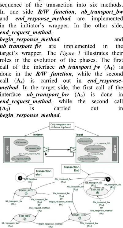
In summary, we dispatch the complete sequence of the transaction into six methods.
In one side R/W function, nb_transport_bw
and end_response_method are implemented
in the initiator’s wrapper. In the other side,
end_request_method,
begin_response_method and
nb_transport_fw are implemented in the
target’s wrapper. The Figure 1 illustrates their roles in the evolution of the phases. The first call of the interface nb_transport_fw (A1) is
done in the R/W function, while the second
call (A4) is carried out in
end_response-method. In the target side, the first call of the
interface nb_transport_bw (A2) is done in
end_request_method, while the second call
(A3) is carried out in
[image:12.595.88.289.136.506.2]begin_response_method.
Figure 1 : Dispatching of communication tasks into several methods in transfer model.
In addition to the complete sequence, BP allows the initiator or the target to complete
the transaction prematurely or to ignore
certain phases. When, looking to Error!
Reference source not found., we note, with
the exception of the call A2, that to each
TLM-2 interface call there are several
possible return calls. For calls A1, A3 and A4
there are respectively 4, 3 and 2 possible
return calls. We say that they mark
respectively the first point of divergence, second point of divergence and the third point of divergence.
Figure 8 extracts and organizes all
possible transaction sequences of BP
according to the following rules:
• Respect the rules of precedence
imposed by the complete sequence;
• A sequence must begin with a call A1;
• A sequence must ends by Ri4 or Ri5;
• A valid sequence is an alternation
between a call and a call return.
This Figure is useful to establish a various methods’ diagram, and to highlight that there are only eight possible graphs of temporal constraints.
The following subsections detail the six
methods: R/W function, nb_transport_bw,
end_response_method, end_request_method,
begin_response_method and
or
or
or
or
or
or
or
1stpoint of
divergence
2edpoint of
divergence
3ed point of
[image:13.595.88.510.80.445.2]divergen ce End of the transaction
Figure 8: Possible transaction sequences in TLM-2 base protocol
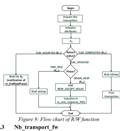
4.2 R/W function
Unlike in transaction model, the R/W function
in transfer model does not necessarily mean the end of the transaction. As shown in Figure 9, this method certainly begins the transaction by calling nb_transport_fw and next it gives way to the other methods. It is obvious that if the target returns TLM_COMPLETED, the transfer model behaves as the transaction model. That is why we preferred to keep the same signature of R/W function of transaction model. In addition, early termination of the transaction indicates that access to the target’s core (i.e. call of the Access function) is performed by the target in nb_transport_fw. Therefore, the
R/W function should restore the transaction to the
memory manager before ending.
Begin
A1
Return value?
TLM_COMPLETED (R15)
TLM_ACCEPTED (R11)
TLM_UPDATED
Wait for A2 (notification of m_EndReqPhase)
Phase?
END_REQ (R12)
BEGIN_RESP (R13)
Wait (delay)
Wait (delay)
End
Injection in m_end_response_PEQ
Acquire the transaction
Free transaction Add
RESP_ACCEPT_DELAY Initialize attributes
Figure 9: Flow chart of R/W function 4.3 Nb_transport_fw
[image:13.595.312.507.463.677.2]API must necessarily generate an error if the phase is different from BEGIN_REQ or END_RESP for compatibility with the base protocol.
At the first point of divergence, if the intended return value is TLM_ACCEPTED or the intended
return phase is BEGIN_RESP, nb_transport_fw must call an Access function
Begin
Phase?
BEGIN_REQ (A1) END_RESP (A4)
Add REQ_ACCEPT_DELAY
Inject in m_request_PEQ
End
tlm::TLM_ACCEPTED Add
REQ_ACCEPT_DELAY Inject in m_response_PEQ
tlm::TLM_UPDATED Add TARGET_DELAY
delay=REQ_ACCEPT_ DELAY delay=REQ_ACCEPT_
DELAY
tlm::TLM_UPDATED Access to core delay=REQ_ACCEPT_
DELAY tlm::TLM_COMLETED
Access to core
Notify m_end_resp_event
tlm::TLM_COMPLETED Notify
m_end_resp_event
tlm::TLM_ACCEPTED
R12
R11 R13
R15
R44 R45
Add REQ_ACCEPT_DELAY
Inject in m_response_PEQ
Add TARGET_DELAY
tlm::TLM_ACCEPTED Or
1st
point of divergence
Phase= END_REQ Phase= BEGIN_RESP
[image:14.595.91.502.207.579.2]3rd point of divergence
Figure 10: Flow chart of nb_transport_fw
4.4 End_request_method
This method deals with the end of the request phase. Its Flow chart is shown in Figure 11. Since
it is sensitive to m_end_request_PEQ, the method
body is simply a loop conditioned by the return value of get_next_transaction (). No point of
divergence is managed by end_request_method as
the only suitable return value of nb_transport_bw call is TLM_ACCEPTED. If this is the case, it
hands over to begin_response_method by injecting
the payload into m_response_PEQ. Otherwise,
end_request_method must generate an error.
Begin
Get_next_tr ansaction() ?
Add TARGET_DELAY
Inject in m_response_PEQ
A2
Return value?
TLM_ACCEPTED (R22)
TLM_COMPLETED TLM_UPDATED
End
NULL
delay=SC_ZERO_T IME
[image:14.595.314.503.561.736.2]Error
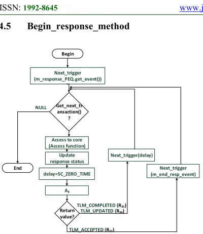
4.5 Begin_response_method
Begin
Get_next_tr ansaction()
?
End
NULL
Access to core (Access function)
Update response status
A3
delay=SC_ZERO_TIME
Return value?
TLM_ACCEPTED (R33)
TLM_COMPLETED (R35)
TLM_UPDATED (R34)
Next_trigger (m_end_resp_event) Next_trigger
(m_response_PEQ.get_event())
[image:15.595.89.289.107.338.2]Next_trigger(delay)
Figure 12. Flow chart of begin_response_method.
As shown in Figure 12, begin_response_method
is sensitive to m_response_PEQ. For each
emerging payload, it performs two main tasks. Firstly, it calls an Access function to actually execute the read or write command requested by
the R/W function. It also means that an update of
the status of the response is also required. Secondly, it calls nb_transport_bw. Whatever its return value, a synchronization point is required. If the return value of the backward interface is
TLM_ACCEPTED, begin_response_method must
wait for the end response notification. In other words, it must wait for A4. If the return value of the backward interface is TLM_UPDATED or
TLM_COMPLETED, begin_response_method
must respect the annotated delay. In both cases, it should call next_trigger () since calling wait () is prohibited in SC_METHOD. This synchronization is required to meet the response exclusion rule imposed by the base protocol. This rule prohibits the target to announce the beginning of a new transaction response as it has not received yet END_RESP of the transaction in progress or that the latter is completed.
4.6 Nb_transport_bw
This method is rather special, since it depends on previous transition made by the current transaction. Whether A2 or A3 call, the designer
must think about keeping track of the last transaction’s transition. For this, we opted for backing up marked transactions in a C++ standard template library (STL) container: std::map. The filling of this container takes place in the R/W
function. The container associates a payload
pointer to previous_tran_phase_enum variable.
The possible values for this variable are ACCEPTED_enum,
UPDATED_END_REQ_enum,
UPDATED_BEGIN_RESP_enum and
END_REQ_enum for respectively R11, R12, R13
and R22 transitions. The search in this container,
within nb_transport_bw, is made easy by using an iterator.
When nb_transport_bw is called with
END_REQ as phase argument, it means that the
caller is end_request_method and the last
transaction’s transition R11. In this case
Nb_transport_bw should verify that the transaction was marked ACCEPTED_enum. In addition, the backward interface must notify the end of the request phase and update marking of the transaction to END_REQ_enum. It means that the last transition is now R22 as shown in Figure. 13.
When nb_transport_bw is called with
BEGIN_RESP as phase argument, it means that the caller is begin_response_method. In this case, the designer must deal with the second point of divergence. He will choose the initiator behaviour towards the A3 call.
Obviously, nb_transport_bw must generate an error if the phase is different from END_REQ or BEGIN_RESP.
Notification of the end of the request phase is used to unlock a R/W function which is waiting
A2. This synchronization point is dictated by the
request exclusion rule. BP’s rule prohibits an initiator to send a new request if it has not received, from the target and for the transaction in progress, the completion of its request phase or the beginning of its response phase
Begin
Phase?
END_REQ (A2) BEGIN_RESP (A3)
Notify m_EndReqPhase
tlm::TLM_ACCEPTED
Update previous transition to R22
Previous transition?
UPDATED_END_REQ_enum (R12)
ACCEPTED_enum (R11)
END_REQ_enum (R22)
Notify m_EndReqPhase
Notify m_EndReqPhase
Delay_PEQ=RESP _ACCEPT_DELAY
Inject in end_response_PEQ
tlm::TLM_ACCEPTED
Delay=RESP_ACCEPT _DELAY
Phase= END_RESP
tlm::TLM_UPDATED
Delay=RESP_ACCEP T_DELAY
tlm::TLM_COMPLETED
R33 R34 R35
2nd point of divergence
Previous transition?
ACCEPTED_enum (R11)
Error
[image:16.595.86.507.90.432.2]End
Figure. 13. Flow chart of nb_transport_bw
4.7 End_response_method
Sensitive to m_end_response_PEQ, this method
performs a test on response status of each emerging payload, to find out success or failure cause of the transaction. In both cases, the initiator’s wrapper must interact with the core to address the situation and then calls nb_transport_fw to complete the transaction as shown in Figure 14. For example, in
case of success of a read command,
end_response_method may call a core method to
copy the data. In case of failure, the core will be notified to be able, for example, to resend the request.
If the return value of the A4 is
TLM_COMPLETED or TLM_ACCEPTED,
end_response_method is responsible to restore the
memory acquired by R/W function to the memory
manager. Otherwise, it generates an error.
Begin
Get_next_tr ansaction() ?
Response status?
TLM_OK_RESPONSE Access to core
A4
Return value?
TLM_COMPLETED (R45)
TLM_ACCEPTED (R44)
Free transaction Deal with
response error
End
NULL
Error
TLM_UPDATED
[image:16.595.322.505.480.697.2]4.8 Integration of temporal constraints
During a BP’s complete sequence and with the AT coding style, a designer can model three temporal constraints, two are set by the target and only one is set by the initiator. In this section, we will explain how to implement these constraints in eight schemes resumed in Figure 8. We must keep in mind that the designer cannot “master” the behaviour of all system’s components, especially when he incorporates third party TL models his design.
The target sets the request_accept_delay: it is the minimum time that the initiator must comply before sending another request. It separates BEGIN_REQ and END_REQ. Suppose we have a transaction with write command, and then BEGIN_REQ marks the moment when the data is ready to be transferred from the initiator to the target. Thus, it marks the moment of sending the first byte. It is then natural that the target will delay END_REQ until it receives the last byte. Nevertheless, according to BP rules, the target is not obliged to notify END_REQ, it may skip this phase to go directly notify the BEGIN_RESP. In this case, the target sets the latency: it is the delay between BEGIN_REQ and BEGIN_RESP. It is the minimum time required for the target to react to the requested order. If the target has already notified the END_REQ, it can delay the BEGIN_RESP
with a target delay. Therefore, in summary, we can
say that:
<target> latency = <target> request_accept_delay + <target> delay
The initiator configures a single time constraint
called response_accept_delay: it separates
BEGIN_RESP and END_RESP. To understand the meaning of this delay, consider a transaction with read command. BEGIN_RESP marks the moment when the data is made available to the initiator. This is, also, the moment when the first byte starting to transit to the initiator. Therefore, the initiator notifies the end of the response when receiving the last byte. Of course, relying on the BP’s rules, this is not an obligation.
Transfer model must take into account the three
temporal constraints mentioned above
(request_accept_delay, target delay, and
response_accept_delay), whatever the sequence
that the designer adopts for the couple initiator and target. The model structure that we described in the previous sub-section allowed us to spread out calls of basic TLM-2 interfaces along four methods. Figure 15 and Figure 16 show how to implement these constraints into different methods.
In the case of the complete sequence of BP,
request_accept_delay delays end_request_method
against R/W function and so against
nb_transport_fw. This delay is implemented as an annotation when the transaction is injected in
m_end_request_PEQ. This PEQ is in the list of
sensitivity of end_request_method.
If we have a sequence where the target omits the end request phase to start directly the response phase, the target, then, injects payload in
m_response_PEQ with an annotation equal to its
latency.
In the sequence N°5, we are in the situation where nb_transport_fw changes the phase of the transaction to END_REQ and at the same time the target calls begin_response_method with a delay equal to its latency. Therefore, the target injects
payload in m_response_PEQ with an annotation
equal to its latency and at the same time, it annotates request_accept_delay. The initiator will honour this constraint by calling wait () within the
R/W function. This situation must not be confused
with sequence N°3 where nb_transport_fw returns TLM_ACCEPTED.
Situations N°7 and N°8 are particular, since there are no calls of backward interface and R/W
function deals directly with the target. In the first
case, it is in charge to inject payload in
m_end_response_PEQ. The delay annotated is the
delay returned by nb_transport_fw plus
response_accept_delay. In the second case, no
injection in PEQ is needed, since transaction is
completed. After calling nb_transport_fw, the R/W
function just calls wait to fulfil a global delay
equal to the target’s latency plus
if (phase == tlm::BEGIN_REQ) {
sc_core::sc_time PEQ_delay_time = delay + TARGET_REQ_ACCEPT_DELAY;
m_request_PEQ.notify(tran, PEQ_delay_time); }
nb_transport_fw
if (command == tlm::TLM_WRITE_COMMAND) {
delay += TARGET_WRITE_DElAY; }
else if (command == tlm::TLM_READ_COMMAND) {
delay += TARGET_READ_DElAY; }
m_response_PEQ.notify(*trans_ptr, delay);
end_request_method
case tlm::BEGIN_RESP : // current transition A3 switch(trans_pair->second)
{
case END_REQ_enum: // previous transition R22 m_bw_path_map.erase(&trans);
m_end_response_PEQ.notify
(trans,INITIATOR_RESP_ACCEPT_DELAY); break;
nb_transport_bw
if (phase == tlm::BEGIN_REQ) {
sc_core::sc_time PEQ_delay_time = delay + TARGET_REQ_ACCEPT_DELAY;
m_request_PEQ.notify(tran, PEQ_delay_time); }
nb_transport_fw
if (command == tlm::TLM_WRITE_COMMAND) {
delay += TARGET_WRITE_DElAY; }
else if (command == tlm::TLM_READ_COMMAND) {
delay += TARGET_READ_DElAY; }
m_response_PEQ.notify(*trans_ptr, delay);
end_request_method
case tlm::BEGIN_RESP : // current transition A3 switch(trans_pair->second)
{
case END_REQ_enum: // previous transition R22 m_bw_path_map.erase(&trans);
phase = tlm::END_RESP;
delay += INITIATOR_RESP_ACCEPT_DELAY; status = tlm::TLM_COMPLETED; break;
nb_transport_bw
if (phase == tlm::BEGIN_REQ) {
sc_core::sc_time PEQ_delay_time = delay + TARGET_REQ_ACCEPT_DELAY;
if (command == tlm::TLM_WRITE_COMMAND) {
PEQ_delay_time += TARGET_WRITE_DElAY; }
else if (command == tlm::TLM_READ_COMMAND) {
PEQ_delay_time += TARGET_READ_DElAY; }
m_response_PEQ.notify(*trans_ptr, PEQ_delay_time); }
nb_transport_fw
case tlm::BEGIN_RESP : // current transition A3 switch(trans_pair->second)
{
case ACCEPTED_enum : // previous transition R11 m_bw_path_map.erase(&trans);
m_end_response_PEQ.notify
(trans,INITIATOR_RESP_ACCEPT_DELAY); m_EndReqPhase.notify(SC_ZERO_TIME); break;
if (phase == tlm::BEGIN_REQ) {
sc_core::sc_time PEQ_delay_time = delay + TARGET_REQ_ACCEPT_DELAY;
if (command == tlm::TLM_WRITE_COMMAND) {
PEQ_delay_time += TARGET_WRITE_DElAY; }
else if (command == tlm::TLM_READ_COMMAND) {
PEQ_delay_time += TARGET_READ_DElAY; }
m_response_PEQ.notify(*trans_ptr, PEQ_delay_time); }
nb_transport_fw nb_transport_bw
case tlm::BEGIN_RESP : // current transition A3 switch(trans_pair->second)
{
case ACCEPTED_enum : // previous transition R11 m_bw_path_map.erase(&trans);
phase = tlm::END_RESP;
delay += INITIATOR_RESP_ACCEPT_DELAY; status = tlm::TLM_COMPLETED; m_EndReqPhase.notify(SC_ZERO_TIME); break;
[image:18.595.86.509.82.723.2]nb_transport_bw
nb_transport_fw
case tlm::BEGIN_RESP : // current transition A3 switch(trans_pair->second)
{
case UPDATED_END_REQ_enum:// prev. Transi. R12 m_bw_path_map.erase(&trans);
m_EndReqPhase.notify(SC_ZERO_TIME); m_end_response_PEQ.notify
(trans,INITIATOR_RESP_ACCEPT_DELAY); break;
nb_transport_bw if (phase == tlm::BEGIN_REQ)
{
sc_core::sc_time PEQ_delay_time = delay + TARGET_REQ_ACCEPT_DELAY;
if (command == tlm::TLM_WRITE_COMMAND) {
PEQ_delay_time += TARGET_WRITE_DElAY; }
else if (command == tlm::TLM_READ_COMMAND) {
PEQ_delay_time += TARGET_READ_DElAY; }
m_response_PEQ.notify(*trans_ptr, PEQ_delay_time);
delay = TARGET_REQ_ACCEPT_DELAY; phase = tlm::END_REQ; status = tlm::TLM_UDATED; }
case tlm::BEGIN_RESP : // current transition A3 switch(trans_pair->second)
{
case UPDATED_END_REQ_enum:// prev. Transi. R12 m_bw_path_map.erase(&trans);
m_EndReqPhase.notify(SC_ZERO_TIME); phase = tlm::END_RESP;
delay += INITIATOR_RESP_ACCEPT_DELAY; status = tlm::TLM_COMPLETED; break;
nb_transport_bw
nb_transport_fw
if (phase == tlm::BEGIN_REQ) {
sc_core::sc_time PEQ_delay_time = delay + TARGET_REQ_ACCEPT_DELAY;
if (command == tlm::TLM_WRITE_COMMAND) {
PEQ_delay_time += TARGET_WRITE_DELAY; }
else if (command == tlm::TLM_READ_COMMAND) {
PEQ_delay_time += TARGET_READ_DELAY; }
m_response_PEQ.notify(*trans_ptr, PEQ_delay_time);
delay = TARGET_REQ_ACCEPT_DELAY; phase = tlm::END_REQ; status = tlm::TLM_UPDATED; }
nb_transport_fw
if (phase == tlm::BEGIN_REQ) {
delay = TARGET_REQ_ACCEPT_DELAY;
//accès au core
// ajout de READ ou WRITE DELAY // m-à-j de la réponse
phase = tlm::BEGIN_RESP; status = tlm::TLM_UPDATED; }
switch (status) {
case tlm::TLM_UPDATED: switch (phase) {
case tlm::BEGIN_RESP:
delay+=INITIATOR_RESP_ACCEPT_DELAY; m_end_response_PEQ.notify(trans,delay);
break;
R/W function
nb_transport_fw
if (phase == tlm::BEGIN_REQ) {
delay = TARGET_REQ_ACCEPT_DELAY;
//accès au core
// ajout de READ ou WRITE DELAY // m-à-j de la réponse
phase = tlm::BEGIN_RESP; status = tlm::TLM_COMPLETED; }
switch (status) {
case tlm::TLM_COMPLETED: //similaire LT if(tran_ptr->get_response_status() == tlm::TLM_OK_RESPONSE) {
delay+=INITIATOR_RESP_ACCEPT_DELAY; if (delay != sc_core::SC_ZERO_TIME) {
wait(delay);
} ret=true; . . . }
m_pool.release(tran_ptr); break;
[image:19.595.92.510.67.705.2]R/W function