EPSON
EPSON TERMINAL PRINTER
5Q-B50/2550
SQ.-BSO/2SS0
• All rights reserved. Reproduction of any part of this manual in any from whatsoever without SEIKO EPSON's express written permission is forbidden. • The contents of this manual are subject to change without notice.
• All efforts have been made to ensure the accuracy of the contents of this manual. However, should any errors be detected, SEIKO EPSON would greatly appreciate being informed of them.
• The above notwithstanding SEIKO EPSON can assume no responsibility for any errors in this manual or the consequences thereof.
PRECAUTIONS
Precautionary notations throughout the text are categorized relative to 1) personal injury, and 2) damage to equipment:
DANGER Signals a precaution which, if ignored, could result in serious or fatal personal injury. Great caution should be exercised in performing procedures preceded by a DANGER headings.
WARNING Signals a precaution which, if ignored, could result in damage to equipment. The precautionary measures itemized below should always be observed when performing repair/main-tenance procedures.
DANGER
1. DANGER OF EXPLOSION IF BATTERY IS INCORRECTRY REPLACED.
REPLACE ONLY WITH SAME OR EQUIVALENT TYPE RECOMMENDED BY SEIKO EPSON CO. DISCARD USED BATTERIES ACCORDING TO GOVERNMENTS, SAFETY INSTRUCTION.
2. ALWAYS DISCONNECT THE PRODUCT FROM BOTH THE POWER SOURCE AND THE HOST COMPUTER BEFORE PERFORMING ANY MAINTENANCE OR REPAIR PROCEDURE.
3. NO WORK SHOULD BE PERFORMED ON THE UNIT BY PERSONS UNFAMILIAR WITH BASIC SAFETY MEASURES AS DICTATED FOR ALL ELECTRONICS TECHNICIANS IN THEIR LINE OF WORK.
4. WHEN PERFORMING TESTING AS DICTATED WITHIN THIS MANUAL, DO NOT CONNECT THE UNIT TO A POWER SOURCE UNTIL INSTRUCTED TO DO SO. WHEN THE POWER SUPPLY CABLE MUST BE CONNECTED, USE EXTREME CAUTION IN WORKING ON POWER SUPPLY AND OTHER ELECTRONIC COMPONENTS.
WARNING
1. REPAIRS ON EPSON PRODUCT SHOULD BE PERFORMED ONLY BY AN EPSON CERTIFIED REPAIR TECHNICIAN.
2. MAKE CERTAIN THAT THE SOURCE VOLTAGE IS THE SAME AS THE RATED VOLTAGE, LISTED ON THE SERIAL NUMBER/RATING PLATE. IF THE EPSON PROD-UCT HAS A PRIMARY-AC RATING DIFFERENT FROM THE AVAILABLE POWER SOURCE, DO NOT CONNECT IT TO THE POWER SOURCE.
3. ALWAYS VERIFYTHATTHE EPSON PRODUCT HAS BEEN DISCONNECTED FROM THE POWER SOURCE BEFORE REMOVING OR REPLACING PRINTED CIRCUIT BOARDS AND/OR INDIVIDUAL CHIPS.
PREFACE
This manual describes functions, theory of electrical and mechanical operations, maintenance, and repair of the 50-850/2550.
The instructions and procedures included herein are intended for the experienced repair technician, and attention should be given to the precautions on the preceding page. The chapters are organized as follows:
Chapter 1
Chapter 2
Chapter 3 Chapter 4
Chapter 5
Chapter 6
Provides a general product overview, lists specifications, and illustrates the main components of the printer.
Describes the theory of printer operation.
Discusses the options
Includes a step-by-step guide for product disassembly, assembly, and adjustment.
Provides Epson-approved techniques for troubleshooting.
Describes preventive maintenance techniques and lists lubricants and adhesives required to service the equipment.
REVISION TABLE
REVISION DATE ISSUED CHANGE DOCUMENT
A April 28, 1989 1st issue
CHAPTER 1.
CHAPTER
2.
CHAPTER
3.
CHAPTER
4.
CHAPTER
5.
CHAPTER
6.
APPENDIX
TABLE OF CONTENTS
GENERAL DESCRIPTION
OPERATING PRINCIPLES
OPTIONAL EQUIPMENTS
DISASSEMBLV, ASSEMBLV, AND ADJUSTMENT
TROUBLESHOOTING
CHAPTER 1
GENERAL DESCRIPTION
1.1 FEATURES 1-1
1.2 SPECIFICATIONS 1-3
1.2.1 Hardware Specifications 1-3
1.2.1.1 Printing 1-3
1.2.1.2 Paper Feed 1-4
1.2.1.3 Paper 1-5
1.2.1.4 Ink 1-10
1.2.1.5 Electrical Specifications 1-11
1.2.1.6 Reliability 1·11
1.2.1.7 Environmental Conditions 1-11 1.2.1.8 Dimensions and Weight 1-12
1.2.2 Software Specifications 1-13
1.2.2.1 Control Code Level... 1-13 1.2.2.2 Input Data Buffer Size 1-13
1.2.2.3 Characters 1-13
1.2.2.4 Printing 1-14
1.3 INTERFACE SPECIFICATIONS 1-18
1.3.1 Parallel Interface Specifications 1-18 1.3.2 RS-232C Serial Interface Specifications 1-21
1.4 FUNCTIONS 1-24
1.4.1 Operating Controls 1-24
1.4.1.1 Power Switch 1-24
1.4.1.2 Control Panel 1-24
1.4.1.3 SelecType 1-28
1.4.1.4 Self Test Function 1-31
1.4.1.5 Hexadecimal Dump Function 1-32 1.4.1.6 Printhead Cleaning and Capping 1-33 1.4.1.7 Ink Charge Function 1-34 1.4.1.8 Paper Load/Eject Function 1-35 1.4.1.9 TOF Adjustment Function 1-36
1.4.1.10 Tear Off Function 1-37
1.4.3 Various Detection Functions 1-40 1.4.3.1 Ink-End Detection Function 1-40 1.4.3.2 Paper-Out Detection and
Forms Override Functions 1-41 1.4.3.3 Cover Open Detection Function 1-42 1.4.3.4 Error Detection Mechanism 1-42
1.4.1.5 Buzzer 1-43
1.5 MAIN COMPONENTS 1-44
1.5.1 Printer Mechanism 1-44
1.5.2 SEIPS/SANPSE Board Unit 1-45
1.5.3 SEIMA Board 1-46
1.5.4 SEIPNL Board 1-47
1.5.5 Housing 1-48
LIST OF FIGURES
Figure 1-1. SQ-850/SQ-2550 Exterior View 1-2
Figure 1-2. Nozzle Configuration 1-3
Figure 1-3. Head Adjust Lever 1-4
Figure 1-4. Cut Sheet Printable Area 1-5 Figure 1-5. Fan-fold Paper Printable Area 1-7 Figure 1-6. Envelope Printable Area 1-8
Figure 1-7. Label Dimensions 1-9
Figure 1-8. Normal Character Matrix 1-15 Figure 1-9. Subscript Character Matrix 1-15 Figure 1-10. Superscript Character Matrix 1-15 Figure 1-11. Interface Timing Chart 1-18 Figure 1-12. 57-30360 36-pin Connector 1-18 Figure 1-13. Handshaking for RS-232C Interface 1-21 Figure 1-14. Serial Data Transmission Timing 1-22 Figure 1-15. Serial Interface Connector 1-22
Figure 1-16. Control Panel 1-24
Figure 1-17. Head Cleaning Timing Chart 1-33 Figure 1-18. Ink Path Conditions at Delivery from the Factory 1-34 Figure 1-19. Paper Conditions Just After Printing 1-38 Figure 1-20. Printer Mechanism Model-441 0/4460 1-44
Figure 1-21. SEIPS Board Unit 1-45
Figure 1-22. SANPSE Board Unit 1-45
Figure 1-23. SEIMA Board 1-46
Figure 1-24. SEIPNL Board 1-47
Figure 1-25. Housing 1-48
LIST OF TABLES
Table 1-1. Table 1-2. Table 1-3. Table 1-4. Table 1-5.
Table 1-6.
Table 1-7. Table 1-8. Table 1-9.
Expendables and Options 1-2
Envelope Specifications 1-8
Dimensions and Weight 1-12
Fonts 1-13
Print Speed, Printable Columns, and
Character Pitch 1-14
Printing Mode, Horizontal Dot Density,
and Character Size 1-16
Bit Image Printing 1-17
8-bit Parallel IIF Connector Pin Assignment 1-19 Printer Select/Deselect Control with
the DC 1/DC3 Code 1-20
1.1 FEATURES
The SO is a high speed 24-nozzle ink jet printer which provides high performance, a low price, high speed printing, and an advanced auto paper handling mechanism. The SO has the following features, in addition to those of the conventional SO-series printers.
• With the standard printer driver ESC/P-84, this printer is compatible with the widest range of computers of any of the SO-and LO-series models.
• Advanced auto paper handling mechanism. Paper selection and load/eject operation can be performed using only the control panel. When the optional CSF (Cut Sheet Feeder) is mounted, switching between cut sheets and fan-fold paper (using the standard push tractor) can be performed without removing the CSF.
• Low noise: 50 dB (A) or less
• Highest printing speed in its class Draft characters: 500 CPS LO characters: 165 CPS
• An 80-column model for personal use and a 136-column model for office work are available.
• Printer operation and selection of various settings are made easier due to the employment of a control panel with a multifunctional LCD (Liquid Crystal Display).
• The amount of ink remaining can be seen at a glance because the ink cartridge includes an ink-level indicator. The ink cartridge can be easily replaced from the front of the printer.
• Printing labels or envelopes is possible. Envelopes can be printed automatically with the optional CSF.
• Optional ID modules are available for easy interfacing to various computers, and font modules provide a wide range of fonts.
Figure 1-1. 5Q-850/5Q-2550 Exterior View
Table 1-1 lists the expendables and options.
Table 1-1. Expendables and Options Code number Name and Description
Expendable 5020002 Exclusive ink cartridge
Option C806111 Double-bin cut sheet feeder for the 50-2550 C806101 Single-bin cut sheet feeder for the 50-2550 C806091 Double-bin cut sheet feeder for the 50-850 C806081 Single-bin cut sheet feeder for the 50-850 C800042 Pull tractor unit for the 50-2550
C800032 Pull tractor unit for the 50-850 #8143 New serial interface #8148 Intelligent serial interface #8165 Intelligent IEEE-488 interface
1.2 SPECIFICATIONS
This section describes the hardware and software specifica ions of the printer.
1.2.1 Hardware Specifications
This section describes the hardware specifications of the printer.
1.2.1.1 Printing
Printing method:
Pin configuration:
Dot pitch:
Column spacing:
On-demand type ink-jet system
24 nozzles (12 nozzles x 2 rows)
0.14 mm (1/180")
2.54 mm (10 CPI)
0.14 mm (180 DPI)
Nozzle Stagger 1 Nozzle Stagger 2
o
:;:l:1 ~2 0o
0#3o
0 O.141mm(1/180')o
:=h
O.282mmo
0o
0o
0o
0o
0'24 { "'41mm
j
'23(1/18)
Gap between the printhead and platen: 1.2
+
0.1 mm (from the nozzle surface to the platen)NOTE: When printing on thick paper, such as an envelope, the platen gap can be adjusted manually to prevent the paper from being stained with ink.
• Dashed line: Standard (1.2 mm) • Solid line: Wide (1.8 mm)
Figure 1·3. Head Adjust Lever 1.2.1.2 Paper Feed
Feeding methods:
Minimum line spacing: Line spacing:
Paper insertion:
Paper feeding speed:
Friction feed Push tractor feed
Push-pull tractor feed (when the optional tractor is used)
1/360" (0.07 mm)
1/6" or 1/8", or any of n/60", n/180", and n/360" (programmable: "n" is a user-defined value)
From the rear
Cut sheets and envelopes: From the upper paper entrance Fan-fold paper and labels: From the lower paper entrance
62 msec. (Line spacing: 1/6")
4.0 IPS (inches/sec., continuous paper feeding) WARNING
• Do not turn the manual paper feed knob, unless a paper jam occurs. The reasons are as follows:
Usually, reverse paper feeding is prohibited by the software to prevent the paper from becoming stained. If the knob is operated manually, this protection is defeated.
Positions set in the SelecType mode, such as TOF or tear-off positions, will be shifted . • Never feed the paper in reverse when printing labels, Because the labels could adhere to
the printer.
1.2.1.3 Paper Cut sheets
Paper width: 50-850 : 182 to 257 mm (7.17 to 10.12") 50-2550: 182 to 364 mm (7.17 to 14.33")
Paper length: 94 to 364 mm (3.70 to 14.33")
Paper thickness: 0.065 to 0.10 mm (0.0026 to 0.004") Paper quality: High quality paper (see Table 1-2.)
Paper weight: 52 g/m2 to 82 g/m2(45 to 70 kg/14 to 22 Ib)
WARNING • 5et the printer in the friction drive mode.
• Do not use paper that is wide than the specified limit.
• Do not manually feed paper in the reverse direction after printing is completed.
~
3.0mm,0.12inch
or more
__- - - i
182-364mm(7.2 -14.3 inch)(136 columns)
3'0~m, 182-257mm(7.2 -10.1 inch)( 80 columns)
0.12 in.
or more
...
Printable Area8.5mm
0.35inch or more
P
r
i
n
t
a
b I
e
25mm 0.98inch 364mm
maximm
A r
e
a
----.-a .
5m m...L_ _- - ' - _ L.... ..J ~.33inch
Fan-fold paper
Paper width:
Paper thickness:
Paper quality:
Paper weight:
SO-850 : 101 to 279 mm (4.00 to 11.00") SO-2550: 101 to 406 mm (4.00 to 16.00")
0.065 to 0.10 mm (0.0026 to 0.004")
High quality paper (See Table 1-2.)
52 to 82 g/m2 (45 to 70 kg/14 to 22 Ib)
WARNING
• Release the friction feed mechanism.
• Do not manually feed the paper in the reverse direction after printing is completed.
• When using push-pull feed, be sure to match the vertical positions of the sprockets on the push tractor and the pull tractor.
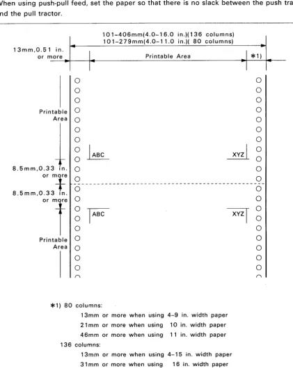
• When using push-pull feed, set the paper so that there is no slack between the push tractor and the pull tractor.
101-406mm(4.0-16.0 in.)(136 columns) 101-279mm(4.0-11.0 in.)( 80 columns)
I
*1)I
Printable AreaI
I
13mm,0.51 in. or more ----1*----t.---l*--'-I~--0 0 0 0 0 0Printable 0 0
Area 0 0
0 0
0 0
0
k
~
00 0
8.5mm,0.33 In. 0 0
or mfe 0 0
-8.5mm,O.33 In. 0 0
O'l
0 00
F
XYZT
00 0
0 0
Printable 0 0
Area 0 0
0 0
0 0
( ) ( )
*1) 80 columns:
13mm or more when using 4-9 in. width paper 21 mm or more when using 10 in. width paper 46mm or more when using 11 in. width paper 136 columns:
[image:21.595.81.503.153.700.2]13mm or more when using 4-15 in. width paper 31 mm or more when using 16 in. width paper
Envelopes See Table 1-2.
Table 1-2. Envelope Specifications
Type No.6 No.10
Height 92 (3.625") 105 mm (4.125")
Width 165 (6.5") 241 mm (9.5")
Thickness 0.16 mm to 0.52 mm (0.0063" to 0.0205")
Weight 12 Ib to 24 Ib (45g/m2 to 91g/m2)
NOTE: The form override function enables printing as close as approximately S.5 mm from the bottom edge of an envelope. However, paper feed accuracy is not guaranteed outside of the printable area shown above by the oblique lines.
WARNING
• Set the envelope so that the longer side is becomes parallel to the platen. • Print at normal room temperature.
• Do not manually feed the paper in the reverse direction after printing is comp leted. • Total paper thickness at the printable area and the non-printable area must not vary more
than 0.25 mm (0.009S").
92mm(3.625 N) or 165mm(6.5 N)
I..
f o o I · - t - - - -105mm(4.125N)or ---~.I
I
241mm(9.5 N) ~
8.5mm(O.33 N)
XYZI
T
~/7////////////~
8.5mm(O.33 N)_.L..-_--.-_
Figure 1-6. Envelope Printable Area
1-8
T
Labels
Dimensions: 63.5 X 23.8 mm (2.5 X 15/16")
101.6 X 23.8 mm (4.0 X 15/16")
101.6 X 36.5 mm (4.0 X 23/16")
NOTE: Dimensions are those of one label on a sheet.
Total paper thickness:
Notes for handling:
Recommended paper:
0.19 mm or less
• Print labels at normal room temperature. • Use only tractor feed labels.
• The dimensions shown above are for the label itself. For the dimensions of the entire sheet, those for fan-fold paper are applicable.
• Never manually feed the paper in the reverse direction. (A label might adhere to the printer.)
AVERY CONTINUOUS FROM LABELS AVERY MINI-LINE LABELS
101.6mm(4 in.)
63.5mm(2.5 in.)
23.8mm (0.94 in.)
36.5mm~
(1.44 in.)1 - - - '
1.2.1.4 Ink
Type:
Color:
Ink cartridge capacity:
Unused residual ink:
Cartridge dimensions:
Cartridge weight:
Ink consumption:
Life of ink cartridge:
Exclusive ink cartridge
Black
105 to 115 cc
20 cc (average value)
109(W) X 157(0) X 44.5(H) mm
Approx. 320 g
0.05 IJ-cc (per 1 dot, see Sections 1.4.1.6 and 1.4.1.7.)
Approx. 6 million characters
(continuous Draft printing/25 dots per character) Approx. 3 million characters
(continuous LQ printing/48 dots per character)
I
NOTE 1: The figures shown above are for when approximately 75 cc of the, total 115 cc is used for actual printing.
Shelf life:
Temperature range:
Within two years from the production date (at normal room temperature)
-30° to 65°C (transit) - 30° to 40°C (storage)
NOTE 2: If the cartridge is transported at 65°C, it must not remain at that temperature for more than 120 hours. If it is transported at 40°C, it should not remain at that temperature for more than one month.
NOTE 3: When the cartridge is stored at 40°C, the shelf life is reduced to one month.
NOTE 4: Ink will freeze if it is stored for a long time at -
rc
or less. If this occurs, use the ink after thawing it. (The time for thawing ink (from -30°C to 25°C) is approximately 2.5 hours at room temperature.)Impact resistance:
Vibration resistance:
Within one drop from 90 cm height (packed/unpacked)
2G, 5 to 55 Hz (packed/unpacked)
NOTE 5: The word "packed" means packed in the cartridge packing box.
Ink safety: No flash point
• Irritant to eyes and skin due to strong alkalinity.
• The result of the AMES test (mutagenicity test for Salmonellas) was negative.
• It is not immediately poisonous if swallowed. (LD50 = 5,000mg or more)
• pH is 12.9 (at 20 C).
DANGER
• If the ink comes into contact with eyes or a wound, consult a doctor immediately.
• If the ink comes into contact with skin (hands), wash it off immediately with soap and plenty of water. If any irritation develops, consult a doctor.
1.2.1.5 Electrical Specifications
Power supply voltage: 108 to 132 VAC (120 V version) 198 to 264 VAC (2201240V version)
Frequency range:
Rated current:
Insulation resistance:
Dielectric strength:
49.5 to 60.5 Hz
Max. 1.0 AIAC (120 V version) Max. 0.6 AlAC (2201240 V version)
10 M ohms or more at 500 VDC (between the AC line andchassis)
1250 VAC (RMS) 1 min. (between the AC line and chassis) (120 V version)
3750 VAC (RMS) 1 min. (between the AC line and chassis)
(2201240 V version)
1.2.1.6 Reliability
MCBF (Mean Cycles Between Failure): MTBF (Mean Time Between Failure):
5 million lines (excluding the printhead)
SO-850 : 4000 POH (Power On Hour, Duty: 25%) SO-2550: 6000 POH (Duty: 25%)
Printhead MCBF: Life of printhead:
30,000 lines (Can be reused after cleaning.)
200 million dots or more (per nozzle), or two years or more nrmal use
1.2.1.7 Environmental Conditions
NOTE1: For the printhead or mechanism only, 5°C to 40°C.
NOTE2: When the printer is stored at 40°C, the shelf life of the ink will be reduced to one month. NOTE3: When the printer is transported at 65°C, it should not remain at that temperature for more
than 120 hours. When it is transported at 40°C, it should not remain at that temperature for more than one month.
Humidity: Operating 10 to 80% (non-condensing) (NOTE 4) Storage 5 to 85% (non-condensing) (NOTE 5) Transit 5 to 85% (non-condensing) (NOTE 5)
NOTE4: For the printhead only, 10 to 85% (non-condensing). NOTE5: For the printhead only, 5 to 90% (non-condinsing).
Vibration resistance: Operating 0.15G, 10 to 55 Hz (X, Y, and Z directions) Storage 0.50G, 10 to 55 Hz (X, Y, and Z directions)
Impact resistance: Operating 1G, within
Storage 2G, within
msec. (X, Y, and Z directions) msec. (X, Y, and Z directions)
1.2.1.8. Dimensions and Weight See Table 1-3.
Table 1-3. Dimensions and Weight 5Q-850
I
5Q-2550 Model-4410 I Model-4460Height 177 mm 142.5 mm
Width 537 mm (NOTE)
I
664 mm (NOTE) 486.5 mmI
613.5 mmDepth 449.6 mm 265 mm
Weight Approx. 12.0Kg
I
Approx. 14.4Kg Approx. 6.4 KgI
Approx. 7.7 Kg NOTE: Include paper feed knob1.2.2. Software Specifications
This section describes the standard software specifications of the printer. 1.2.2.1 Control Code Level
EPSON ESC/P 24-84
1.2.2.2 Input Data Buffer Size Approx. 8K bytes
1.2.2.3 Characters Character code: 8 bits
Character set:
Fonts:
96 ASCII characters
14 international character sets
See Table 1-4.
Table 1-4. Fonts
Family No. 10CPI 12CPI 15CPI Proportiona I
EPSON Roman 0 0 0 0 0
EPSON Sans Serif 1 0 0 0 0
EPSON Courier 2 0 0 0
*
EPSON Prestige 3 0 0 0
*
EPSON Script 4 0 0 0
*
EPSON OCR-B 5 0
*
x*
EPSON OCR-A 6 0
*
x*
EPSON Orator 7 0
*
x*
EPSON Orator-S 8 0
*
x*
EPSON Draft
- -
0 0 0 xxNOTE: 0 resident
*
desired pitch is made by software using selected font x print Roman 15CPI font1.2.2.4 Printing
Print direction: Bidirectional logic seeking
Print speed, printable columns, and character pitch: See Table 1-5.
Table 1-5. Print Speed, Printable Columns, and Character Pitch
Printing Mode Printable Columns(CPL) Character Print Speed (CPS) Pitch (CPI)
SQ-850 SQ-2550 Draft LQ
10 pitch
Normal 80 136 10 500 165
Emphasized 80 136 10 248 165
Enlarged 40 68 5 248 83
Emphasized+enlarged 40 40 5 124 83
Condensed 137 233 17.1 424 283
Condensed + enlarged 68 116 8.5 212 141
12 pitch
Normal 96 163 12 600 198
Emphasized 96 163 12 297 198
Enlarged 48 81 6 297 99
Emphasized + enlarged 48 81 6 297 99
Condensed 160 272 20 495 330
Condensed + enlarged 80 136 10 248 165
15 pitch
Normal 120 204 15 743 247
Emphasized 120 204 15 371 247
Enlarged 60 102 7.5 371 124
Emphasized + enlarged 60 102 7.5 186 124
Proportional
Normal Max. 68 116 8.6
-
141Min. 160 272 20
-
330Enlarged Max. 34 58 4.3
-
71Min. 80 136 10
-
165Condensed Max. 137 233 17.1
-
283Max. 320 544 40 - 660
Condensed + Max. 68 116 8.6 - 142
enlarged Min. 160 272 20
-
330Proportional, super/subscript
Normal Max. 102 174 12.8
-
212Min. 240 408 30 - 495
Enlarged Max. 51 87 6.4
-
106Min. 120 204 15
-
248Condensed Max. 205 349 25.7 - 424
Min. 480 816 60 - 990
Condensed + Max. 102 174 12.8 - 212
enlarged Min. 240 408 30 - 495
NOTE: Max indicates the value when only maximum width characters are printed. Min indicates the value when only minimum width characters are printed.
Character matrix: See Table 1-6 and Figures 1-8 to 1-10. The upper two dots are the ascender area, and the lower four dots are the descender area. The lowest dot is used for printing an underline.
(Normal Character)
I
2 Ascender Area 3
4 L
5 E R
6 F I
7 T G
8 Ascender Area(l5pitchl H
9 S T
10 P
11 A S
12 C P
13 E A
14 (00 C
15 E 16 (02) 17 18 19 20 21 Descender Area 22 23 24
I..
Face Width (01).1
Character Width (CW)
Figure 1-8. Nomal Character Matrix
9
10 L R
11 E I
12 F G
13 T H
14 T
15 S
16 P S
17 A p
18 C A
19 E C
20 E
21 22 23 24
Figure 1-9. Subscript Character Matrix
I
2 L R
3 E I
4 F G
5 T H
6 T
7 S
8 p S
9 A p
10 C A
11 E C
12 E
13 14 15 16
Table 1-6. Printing Mode, Horizontal Dot Density, and Character Size
Printing Mode Horizontal Dot Character Width Character Height Density (aO
+
a1+
a2) (W X H mm)Draft, 10 pitch 120 12 1.9 X 3.2
Draft, 12 pitch 120 10 1.9 X 3.2
Draft, 15 pitch 120 8 1.9 X 3.2
Draft, 10 pitch, Condensed 240 14 1.0 X 3.2
Draft, 12 pitch, Condensed 240 12 1.0 X 3.2
La, 10 pitch 360 36 2.2 X 3.2
La, 12 pitch 360 30 1.9 X 3.2
La, 15 pitch 360 24 1.9 X 2.3
La, 10 pitch, condensed 360 21 1.2 X 3.2
La, 12 pitch, condensed 360 18 1.0 X 3.2
Max.42 2.6 X 3.2
La, proportional 360
Min. 18 1.0 X 3.2 Max. 21 1.3 X 3.2 La, proportional, densed 360
Min. 9 0.5 X 3.2 Max.28 1.8 X 2.3 La, proportional,super/subscript 360
Min. 12 0.7 X 2.3 La, proportional, super/subscript, Max. 14 0.9 X 2.3
360
condensed Min. 6 0.4 X 2.3
NOTE 1: Character size in the above table is forthe largest character, and the value changes depending on the paper or ribbon being used.
NOTE 2: The 3.2 mm high character and the 2.3 mm high character are constructed using 23 dots (vertical) and 16 dots (vertical), respectively.
NOTE 3: Dots that adjoin horizontally are not printed.
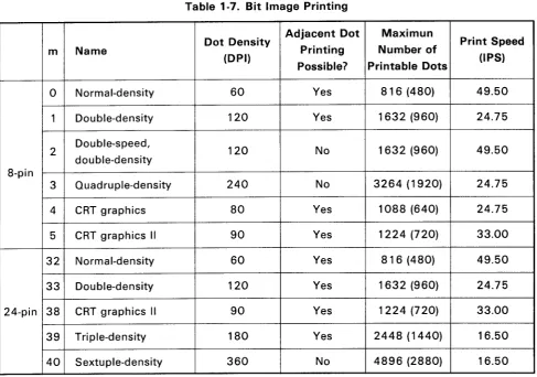
Bit image printing: See Table 1-7.
Table 1-7. Bit Image Printing
Dot Density Adjacent Dot Maximun Print Speed
m Name Printing Number of
(DPI)
Possible? Printable Dots UPS)
0 Normal-density 60 Yes 816 (480) 49.50
1 Double-density 120 Yes 1632 (960) 24.75
2 Double-speed, 120 No 1632 (960) 49.50
double-density 8-pin
3 Quadruple-density 240 No 3264 (1920) 24.75
4 CRT graphics 80 Yes 1088 (640) 24.75
5 CRT graphics II 90 Yes 1224 (720) 33.00
32 Normal-density 60 Yes 816 (480) 49.50
33 Double-density 120 Yes 1632 (960) 24.75
24-pin 38 CRT graphics 11 90 Yes 1224 (720) 33.00
39 Triple-density 180 Yes 2448 (1440) 16.50
40 Sextuple-density 360 No 4896 (2880) 16.50
NOTE1: The parenthesized values apply to the SQ-850.
NOTE2: 'm" is the m in the command format < ESC * m n 1 n2 >.
NOTE3: 'Yes" and "No" in the column "Adjacent Dot Printing Possible?" are equivalent to "including half dots" and "excluding half dots" in the normal printing mode.
1.3 INTERFACE SPECIFICATIONS
The printer is equipped with standard 8-bit parallel and RS-232C compatible interfaces. Moreover, it is possible to interface to various computers using the optional interface board. This section describes the specifications of the standard interfaces. (For details of the optional interface board, see Chapter 3 or the "Option Interface Manual."
1.3.1 Parallel Interface Specifications
Data transmission mode: Communication mode: Handshake:
Signal levels:
Adaptable connector:
8-bit parallel
Uses a STROBE pulse from outside the printer. Uses the ACKNLG and BUSY signals.
Input data and all interface control signals are TTL compatible. 36-pin Amphenol 57-30360 or equivalent
NOTE: It is recommended that the interface cable be as short as possible.
BUSY
ACKNLG
DATA
STROBE
5tls 5tlS
typ. typ.
Figure 1-11. Interface Timing Chart
14. AUTOFEED X
IS. NC
15. GND
17. CHASSISGND
lB. NC I. STROBE 2. DATAl 3.DATA2 4.DATA3 5.DATA4 5. DATA5 7.DATA5 B. DATA7
9. OAT AB
10. ACKNLG
I!. BUSY
12.PE
13. +5V
19. GND(Pa:r",:thl.) 20. GND(P.:r",:th2') 21. GND(Pa:r",ah 3,) 22. GND(Pa:r",:th 4.) 23. GND(Pa:r"':th5.) 24. GND (Pa:r",:th5')
---ur=~~:JU---25.GND(Pa:r",:th7')
- - - f - H - - - i l I J [ ] ] J - - t H - - - 2 5 . GND(Pa:r",:thB.)
---ttr=~~-1M'---27.GND (Pa:r",:th9.)
- - - 2 B . GND(P.:r",:thIO.)
29. GND(Pa:r",:th 11.) 30. GND (Pa:r",:th 12.) 31. INIT 32. ERROR 33. GND 34. NC 35. +5V 35. SLCTIN
Figure 1-12. 57-30360 36-pin Connector
Table 1-8. 8-Bit Parallel IIF Connector Pin Assignments
Pin No. Signal Return I/O Description
Strobe pulse to read the input data. Pulse width must be 1 STROBE 19 I more than 0.5 p,s. Input data is latched after falling edge of
this signal.
2 DATA 1 20 I Parallel input data to the printer. 3 DATA2 21 I "HIGH" level means data "1". 4 DATA3 22 I "LOW" level means data "0".
5 DATA4 23 I
6 DATA5 24 I
7 DATA6 25 I
8 DATA7 26 I
9 DATA8 27 I
This pulse indicates data are received and the printer is 10 ACKNLG 28 0 ready to accept next data.
Pulse width is approx. 10 p,s. (See NOTE5)
11 BUSY 29 0 "HIGH" indicates printer can not accept data.
(See NOTE5)
12 PE 30 0 "HIGH" indicates paper-out.
This signal is effective only when ERROR signal is "LOW".
13 SLCT - 0 Always "HIGH". (Pulled up to +5V through 3.3 K ohms
resistor.)
If this signal is "LOW" when the printer is initialized, a line 14 AUTOFEED-XT
-
I feed is automatically performed by input of "CR" code. (SeeNOTE6)
15 Not used.
16 GND Ground for twisted-pair.
17 Chassis GND - - Printer chassis ground.
18 Not used.
19to 30 GND Ground for twisted-pair.
31 INIT 16 I Pulse (width: 50 p,s min., active "LOW") input for printer initialization.
"LOW" indicates that some error has occurred in the printer.
32 ERROR 0
(Refer to section 1.4.3.4)
33 GND - - Ground for twisted-pair.
34 - - Not used.
35 - 0 Always "HIGH". (Pulled up to +5V through 3.3 K ohms
resistor.)
If the signal is "LOW" when printer is initialized, the
36 SLECT-IN - I
DC 1/DC3 control is disabled. (See NOTE6 and Table 1-9)
NOTE 1: The signals with a bar over the name are active-Iow.
NOTE 3: All interface conditions are based on TTL levels. Both the rise and fall times of all signals must be 0.2 ILsec. or less.
NOTE 4: Refer to the Interface Timing Chart (Figure 1-11) for details on each signal.
NOTE 5: Data transfer protocol must not ignore the ACKNLG or BUSY signal. (Data can be transferred after either recognizing the ACKNLG signal or when the BUSY signal is LOW.)
NOTE 6: The AUTO FEED XT and SLCT IN signals will be valid when "AUTO LF" and "DC 1/DC3" are set "ON" and "VALID", respectively, in the SelecType mode.
NOTE 7: Printing tests, including those of the interface circuits, can be executed without using external equipment by setting the DATA 1 to DATA8 lines of the interface connector to certain codes (1 for GND open, and 0 for short) and connecting the ACKNLG signal to the STROBE signal.
Table 1-9. Printer Select/Deselect Control with the DC1/DC3 Code
SLCTIN
Printer Receive ERROR BUSY
State Signal Code Signal Signal ACKNLG Data Processing Input
OFF LINE High DC1 Low High Not output Data entry disabled (Error)
DC3
Low DC1
DC3
ON LINE High DC1 High Low (NOTE1) Output after Data entry (normal each data processing). entry
DC3 High Low Output after Data entry enabled, (NOTE 1) each data However, input data is
entry ignored (waits for DC 1, NOTE 2).
Low DC1 High Low (NOTE1) Output after Data entry enabled each data (normal processing) entry
DC3 High Low (NOTE1) Output after each data entry
NOTE 1: BUSY = LOW" is the state before data is input. During data processing, the BUSY signal goes HIGH and LOW alternately.
NOTE 2: After the DC3 code is input, input data is ignored until the DC 1 code is input.
NOTE 3: In the above table, it is assumed that no ERRORs other than those due to OFF LINE occur. NOTE 4: The DC1/DC3 control is valid only when "DC1/DC3" is set to"VALlD" (default setting in the
SelecType mode) at printer initialization and the SLCT IN signal from the host computer is HIGH. At this time, the printer starts operation in the DC 1 state.
NOTE 5: The DC1/DC3 control will be invalid even with "DC1/DC3" set to "VALID" (default setting in the SelecType mode) at printer initialization, if the SLCT IN signal from the host computer is LOW.
1.3.2 RS-232C Serial Interface Specifications
Table 1-10. Serial Interface Handshaking
DTR Signal X-ON/OFF protocol Description
MARK X-OFF (DC3/13H) When the number of bytes remaining in the input buffer reaches 256 or less, the signal level goes to MARK, or an X-OFF code is sent to the host com-puter. This indicates that the printer is not ready to receive data.
SPACE X-ON (DC 1/11 H) When the number of bytes remaining in the input buffer reaches 512 or more, the signal level goes to SPACE, or an X-ON code is sent to the host computer. This indicates that the printer is ready to receive data.
DTR (REV) Signal
MARK I -1ZV) ---~~~~~~~
1I
11
SPASE (
+
1ZV) l )512 byte Z56byte
X-ON X-OFF
byte Input Buffer Vacant Area
X-ON/X-OFF Protocol
Word Length:
Bit Rate:
Logic Level:
Figure 1-13. Handshaking for RS-232C Interface
Start bit 1 Data bits 8
Parity Odd, Even, or none Stop bits... 1 bit or more
300,600,1200,2400,4800, 9600, or 19200 BPS
T -( +V) DTR (-V) (+V) ---RXD (-V)
Data Bit
i----I..--~I-Start Bit Parity Bit DTR Handshake
--[--[~~
-- -- ~~ l T
-Stop Bit
--[--[U.
-- -- U·
Start Parity
Bit Bit
RX~+V)
(- V)?I~I~I~I~I~I~I~~~~i--J1t---~f---
Data Bit(+V)
TXD
(-V)
Start Data Bit Bit (X-OFF)
X-ON/X-OFF Protocol
Start Data Bit Bit (X-ON)
Figure 1-14. Serial Data Transmission Timing NOTES: 1. The value of 'T' varies according to the input data.
2. The word structure of serial data is 1 start bit
+
8 data bits+
bits+
parity (Odd, Even, or none)+
1 or more stop bits.Error Detection: Parity error * .. is printed. Overrun error lgnored Framing error lgnored
Connector: D-SUB 25-pin connector (See Figure 1-5.) Connector Pin Assignments: Refer to Table 1-11.
4.NC 5.NC G.NC 7. NC a.NC 9.NC 20.DTR 21.NC 22.NC 23.NC 24.NC 25.NC
ASSIS GND
~
D II
D
,
,
I,
NAL GND v®
t.CH 2.1X 3.RX 4.NC 5.NC 6.NC 7.SIG a.NC 9.NC 'O.NC It.RE '2.NC 13.NCFigure 1-15. Serial Interface Connector
Table 1-11. RS-232C Serial Interface Connector Pin Assignments
Pin No. Signal Dir. Description
2 TXD 0 Transmit data.
20 DTR 0 Indicates when printer is ready to receive data. "MARK" level indicates printer is not ready to receive data. 11 REV(=2nd RTS) 0 Same as DTR.
3 RXD I Receive data.
7 SIGNAL GND - Signal (Logic) ground level. 1 CHASSIS GND
-
Printer chassis ground.1.4
FUNCTIONS
This section describes functions of the printer other than printing.
1.4.1 Operating Controls
This section describes the functions that the user controls, and the functions that display messages for the user.
1.4.1.1 Power Switch
The POWER switch on the left side of the printer is used to turn the printer on and off. When the printer is turned on or off, it is reset (see Section 1.4.2).
NOTE: Do not turn the printer power on when the ink cartridge is not mounted. 1.4.1.2 Control Panel
This section describes switches and indicators on the control panel. The control panel consists of nine switches, six indicators, and a 20-column LCD (Liquid Crystal Display). Figureure 1-16 shows the control panel. (The letter identifying each description below match those in the figure.)
I I I I
k m
/I
EOWE~
e:b
READYcb
6~~ER
cb
INKE~ND~~~~~~-r--::M:::IC71=-BlFfFE=ED-rrJ
I
Vn
.6
r
!
I
GCLEANIN~ESET
L..- --' =SelecType D
=MENU SELECTION ~ =
r - - . PAPER ep
F~ PITCH SELECT (TEAR OFF
If 11
I I I , I Q
I
a b c n dI 0 e f
Figure 1·16. Control Panel
1-24
Switches
a. FONT
This switch is used to select the standard or external (option) font. The current font is always displayed on the LCD. Each time this switch is pressed, the font selection changes. This switch is valid in both the ON LINE and OFF LINE modes. Font selection changes in the sequence shown in Table 1-4.
b. PITCH
This switch is used to select the print pitch. The current print pitch is always displayed on the LCD. Each time this switch is pressed, the pitch selection changes. This switch is valid in both the ON LINE and OFF LINE modes. Print pitch selection changes in the sequence shown below.
c. PAPER SELECT
This switch is used to select the paper type. Each time this switch is pressed, the display on the LCD and the paper feed mechanism selection change in the sequence shown below.
I
TracorI
~
I
FrictionI
~
I
CSF bin 1I
~ [CSF~ ~
I
TractorI
~
I
FrictionI
~
• • • • • • • • • •
The CSF setting "CSF Bin 1/2" is displayed only when the CSF is mounted. When the CSF is mounted, the word "Friction" will be omitted from the display. This switch is valid only in the OFF LINE mode.
d. TEAR OFF
This switch is valid only when fan-fold paper is used. Pressing this switch advances the paper to the tear off (paper cut off) position. Pressing it again feeds the paper in reverse to the TOF position. This switch is valid both in the ON LINE and OFF LINE modes.
e. ON LINE
This switch sets the printer either ON LINE or OFF LINE. Normally, the printer is ON LINE when the printer is turned on, and waits for data from the host computer. When the printer is set OFF LINE, it immediately stops printing, and enters the BUSY state.
f. FORM FEED
Pressing this switch advances the paper to the first line (TOF position) of the next page. This switch is valid only in the OFF LINE mode.
g. LINE FEED
Lightly pressing this switch once advances the paper one line. When the switch is pressed continuously (for 0.5 sec. or more), the paper advances continuously.The switch is valid only in the OFF LINE mode.
h. LOAD/EJECT
i. MICRO FEED
These switches are used to adjust the paper position. When the switch or the switch are pressed, the paper advances forward or backward a little bit (micro feed). These switches can be used to adjust the paper position during TOF position adjustment or tear-off position adjustment.
(See Sections 1.4.1.9 and 1.4.1.10.)
Some of the above switches can be used in combination. The operation is identified by the printer when the switches are released.
e
+
f. SelecType modeWhen the ON LINE and FORM FEED switches are pressed simultaneously, the printer enters the SelecType mode (Panel setting mode). This operation is valid both in the ON LINE and OFF LINE modes. (See Section 1.4.1.3.)
e
+
g. CLEANINGWhen the ON LINE and LINE FEED switches are pressed simultaneously, head cleaning is executed. This operation is valid only in the OFF LINE mode.
(See Section 1.4.1.6.)
e
+
h. RESETWhen the ON LINE and LOAD/EJECT switches are pressed simultaneously, the printer is reset. This operation is valid both in the ON LINE and OFF LINE modes. (See Section 1.4.2.)
Indicators
j. POWER (Green LED)
Lights when the power switch is on (AC power is supplied) and the power supply circuit is operating normally.
k. READY (Green LED)
Lights when the printer is ready to receive data (ON LINE: READY).
I. PAPER OUT (Red LED)
Lights when the printer detects the paper out state.
m. INK END (Red LED)
Lights when the printer detects the ink-out state or when the ink cartridge is not mounted. n. TEAR OFF (Orange LED)
Lights while the TEAR OFF switch is pressed and the tear off operation is being executed.
o. ON LINE (Green LED)
Lights when the printer is ON LINE. Goes off when the printer is OFF LINE.
Leo
The printer has an LCD (20 columns x 1 row) on the control panel. The LCD displays the current font in the 1st to 8th columns, the current character pitch at the center, and the current paper feed mechanism in the 13th to 20th columns .
• Paper feed mechanism Friction
Tractor CSF bin 1 CSF bin2 • Pitch
10 (1 Ocpi) 12 (1 2cpi) 15 (15cpi) 17 (17.cpi) 20 (20cpi) PS (Proportional) • Font Draft Roman
S Serif (Sans Serif) Courier Prestige Prestige Script OCR-A OCR-B Oractor Oractor-S
Other messages displayed on the LCD and their meanings are as follows: PAPER OUT
INK END SELF TEST HEX DUMP TOF ADJUST TEAR OFF ADJUST
COVER OPEN ERROR DD
CLEANING
INK CHARGE (time)
PLEASE TEAR OFF
:Indicates the printer is out of paper.
:Indicates the printer is out of ink, or no ink cartridge is mounted. :Indicates that a self test is being executed.
:Indicates that the printer is in the hexadecimal dump mode. :Displayed during TOF position adjustment (See Section 1.4.1.9.) :Displayed during the tear off position adjustment
(See Section 1.4.1.10.)
:Displayed if the printer cover is open.
:Displayed if an error occurred. The error number is displayed to indicate the error type. (For details, see Section 1.4.3.4 and Chapter 5.)
o
= No C.G. ROM is mounted, or the C.G. ROM is defective. 3=
Defective READ/WRITE operation of the EEPROM 10 = Carriage motor control error20 = CPU error
:Displayed during head cleaning (See Section 1.4.1.6.)
:Displayed during ink supply operation. The time it takes to complete supplying the ink is also displayed. (See Section 1.4.1.7.)
1.4.1.3 SelecType
This section describes the SelecType (Panel setting) function.
In the SelecType mode, default value settings can be selected using the four switches on the control panel and messages displayed on the LCD.
• Entering the SelecType mode.
Press both the
I
ON LINEI
andI
FORM FEEDI
switches.• If these switches are pressed again, the printer exits the SelecType mo,de (exits the panel setting mode).
Values will become valid as they are set in the SelecType mode. However, the following settings will become valid the next time the printer power is turned on.
ON/OFF of Auto LF Valid/Invalid of DC 1/DC3
Once the values are set, they are stored in the memory, which is backed up. Since the settings will remain even after the printer power is turned off, the values displayed on the LCD will be set as default values the next time the printer power is turned on. Therefore, the printer has no DIP switches. Back up is performed with a battery, and requires no maintenance.
The following page shows the operation flow in the SelecType mode.
If you want to reset the default settings to the factory set values, clear the memory as described below:
• Clearing the memory
Turn the printer power on while pressing both the
I
ON LINEI
andI
LOAD/EJECTI
switches.When the memory is cleared correctly, the following message will be displayed on the LCD:
I
MEMORY CLEARMessages displayed on the LCD change in the sequence shown in the Table below, and the buzzer rings.
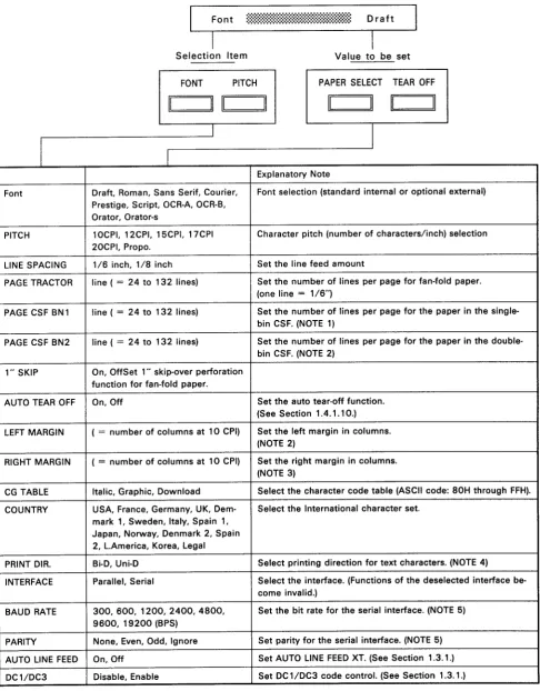
Table 1-12. Operation Flow in the SelecType Mode
Selection Item Value to be set
FONT PITCH PAPER SELECT TEAR OFF
11 11 11 11 11 11 11 11
I
I
I
I
Explanatory Note
Font Draft, Roman, Sans Serif, Courier, Font selection (standard internal or optional external) Prestige, Script, OCR-A, OCR-B,
Orator, Orator-s
PITCH 10CPI, 12CPI, 15CPI, 17CPI Character pitch (number of characters/inch) selection 20CPI, Propo.
LINE SPACING 1/6 inch, 1/8 inch Set the line feed amount
PAGE TRACTOR line (= 24 to 132 lines) Set the number of lines per page for fan-fold paper. (one line = 1/6")
PAGE CSF BN1 line (= 24 to 132 lines) Set the number of lines per page for the paper in the single-bin CSF. (NOTE 1)
PAGE CSF BN2 line (= 24 to 132 lines) Set the number of lines per page for the paper in the double-bin CSF. (NOTE 2)
1" SKIP On, OffSet 1" skip-over perforation function for fan-fold paper.
AUTO TEAR OFF On, Off Set the auto tear-off function. (See Section 1.4.1.10.)
LEFT MARGIN ( = number of columns at 10 CPI) Set the left margin in columns. (NOTE 2)
RIGHT MARGIN ( = number of columns at 10 CPI) Set the right margin in columns. (NOTE 3)
CG TABLE Italic, Graphic, Download Select the character code table (ASCII code: 80H through FFH).
COUNTRY USA, France, Germany, UK, Dem- Select the International character set. mark 1, Sweden, Italy, Spain 1,
Japan, Norway, Denmark 2, Spain 2, L.America, Korea, Legal
PRINT DIR. Bi-D, Uni-D Select printing direction for text characters. (NOTE 4)
INTERFACE Parallel, Serial Select the interface. (Functions of the deselected interface be-come invalid.)
BAUD RATE 300,600,1200,2400,4800, Set the bit rate for the serial interface. (NOTE 5) 9600, 19200 (BPS)
NOTE 1: Displayed only when the CSF is mounted.
NOTE 2: Range of the left margin is as follows:
SO-850 : 0 to 45 columns SO-2550: 0 to 80 columns
The left margin must not exceed the right margin.
NOTE 3: Range of the right margin is automatically calculated from the left margin as shown below:
SO-850 : Left margin
+
1 to 80 columns SO-2550: Left margin+
1 to 136 columnsNOTE
4:
Displayed only when the serial interface is selected. (Not displayed when the parallel interface is selected.)NOTE 5: Displayed only when the Serial interface is selected.
NOTE 6: Since the following combinations are impossible, they will be automatically ignored.
Draft
+
Proportional OCR-A+
15 CPI OCR-B+
15 CPI Orator+
15 CPI Orator-S+
15 CPINOTE 7: The values set in the SelecType mode will be printed when the self test is executed.
1.4.1.4 Self Test Function
The printer has self test functions to check the following items:
• PROM version number • Panel settings
• Control circuit functions
• Printer mechanism functions and print quality
The settings changed in the SelecType mode are printed in the self test mode. When a self test is executed using paper from the CSF, the page length is calculated by feeding the paper using 1/6" line
feeds, and 'This is the first line." and "This is D D line." are printed on the first and last lines of the first page, respectively. In this way, you can confirm the number of printable lines.
When an error occurs, the location of the problem (the host computer or the printer) can be determined by executing the self test. The self test operation flow is shown below:
Starting the self test in the Draft mode
Turn the printer power on while pressing the
I
LINE FEEDI
switch.Starting the self test in the LQ mode
Turn the printer power on while pressing the
I
FORM FEEDI
switch.Stopping or resuming the self test
Press the
I
ON LINEI
switch. (The ON LINE LED does not light.)Exiting the self test mode
Stop printing by pressing the
I
ON LINEI
switch, then turn the printer power off. WARNING1.4.1.5 Hexadecimal Dump Function
The hexadecimal dump (HEX. dump) function causes the printer to print the received data in hexadecimal. The printer prints 16 values in hexadecimal, followed by the corresponding ASCII characters on one line. If there is no corresponding printable character for a value (e.g. a control code), a period (.) is printed. If less than 16 values remain at the end of the dump, the last line can be printed by pressing the ON LINE switch.
When the printer is in the hexadecimal dump mode, it cannot enter the SelecType mode. (Some of the settings changed in the SelecType mode are reflected in the printing format.)
If trouble occurs, the hexadecimal dump function can be used to check if the data from the host computer is correct.
Entering the hexadecimal dump mode
Turn the printer power on while pressing both the
I
FORM FEEDI
andI
LINE FEEDI
switches.Stopping and exiting the hexadecimal dump mode
Stop printing by pressing the
I
ON LINEI
switch, then turn the printer power off.NOTE: To exit the hexadecimal dump mode, be sure to stop printing first as described above. If the stop operation is omitted, the printhead cannot be capped correctly. This might cause trouble (e.g. the printhead could clog or the carriage might operate abnormally).
145.6 hours
1.4.1.6 Printhead Cleaning and Capping
The printer has cleaning and capping functions to protect the printhead from damage (for details of each operation, see Chapter 2).There are two types of cleaning, arbitrary and automatic. Normally, the printhead is capped to prevent from damage. Arbitrary cleaning is required when printing becomes abnormal (e.g. a specific dot is missing, or the printing color is not uniform).
WARNING
• Turn the printer power off only after confirming that the printhead is capped. If the printhead has been uncapped for a long time, printing might be abnormal (e.g. a specific dot is missing) because the printhead gets dried out and clogs.
• Never turn the printer power off during cleaning. (The reasons are the same as those described above.)
• Do not execute cleaning unnecessarily. The life of the ink cartridge will be shortened.
Arbitrary cleaning
Press both the I-O-N-L-I-N-E-'I and
I
LINE FEEDI
switches when the printer is OFF LINE.Automatic cleaning
The printer automatically executes cleaning in the following cases:
• When the printer power is turned on after 145.6 hours or more have passed since the last cleaning operation.
~
~
[Power ON:Cleaning is not executed
CI~aningp:~
, = _
C
Power ON:Cleaning is executedF=====
= = = = = = = = = =
II I I
Figure 1-17. Head Cleaning Timing Chart
• When the printer power is turned on and the printhead is found to be uncapped. • When the printer is reset with the printhead uncapped.
Similarly, capping will be executed in the following cases:
• If printing is not executed continuously while the printer power is on. (When a few seconds have passed after printing had been stopped.)
For reference, the amount of ink consumed when cleaning or capping is executed or when printer initialization is executed at power on are as follows:
Automatic cleaning at time-out :Approx. 0.5 cc
Arbitrary cleaning :Approx. 2.0 cc
1.4.1.7 Ink Charge Function
The following operations are performed before the printer is delivered from the factory to prevent the printhead from being damaged (so that it can be stored indefinitely):
• The ink path is cleaned using a special cleaning liquid. • The cleaning liquid is completely discharged.
• The printhead is capped. • The ink cartridge is removed.
Ink cartridge removal
Ink path cleaning
(removes ink used for printing inspection)
Figure 1-18. Ink Path Conditions at Delivery from the Factory The ink supply operation is used to prepare the printer after storage.
Step 1: Remove all protective parts that were installed for transit. (For the protective parts, see Chapter
4.)
Step 2: Mount the ink cartridge.
Step 3: Turn the printer power on while pressing both the
I
ON LINEI
andI
LINE FEEDI
switches. During the ink supply operation, the LCD displays "INK CHARGE XXX." XXX indicates the time required to complete the operation, and it will be completed when the value reaches 000.For reference, the amount of ink consumed during the ink supply operation is approximately 15cc.
1.4.1.8 Paper Load/Eject Function
WARNING
• Do not turn the manual paper feed knob, unless a paper jam occurs. The reasons are as follows:
Usually, reverse paper feeding is prohibited by the software to prevent the paper from being smudged. If the feed knob is operated manually, this protection is overriden.
Positions set in the SelecType mode, such as TOF or tear off positions, will be shifted . • Never feed the paper in the reverse direction when printing labels. Otherwis a label might
adhere to the printer.
Paper handling in this printer is completely automated. By pressing the corresponding switch on the control panel, the printer executes as follows:
• Loading/ejecting a cut sheet
1. Set a cut sheet at the sheet guide. 2. Press the
I
LOAD/EJECTI
switch.1
When the printer is in the paper out state: Loads the paper
(advances the paper to the TOP position, then stops).
When the paper is in the printer: Ejects the paper.
1
When the printer is in the paper out state:Loads the paper (advances to the TOF position, then stops).When the paper is in the printer: Executes back out.
(Back out: Feeds the paper in the reverse direction, then ejects it.) • Loading/ejecting fan-fold paper
1. Set the paper at the sprockets of the tractor. 2. Press the
I
LOAD/EJECTI
switch.• Switching between tractor and friction feed (cut sheet/CSF) mechanisms Switching from the tractor to the friction mechanism
1. Press the PAPER SELECT switch. 2. Back out the fan-fold paper.
3. Cancel the push tractor mechanism, then select the friction mechanism. 4. Load the paper from the sheet guide or the CSF.
Switching from the friction to the tractor mechanism 1. Press the PAPER SELECT switch.
2. Eject the cut sheet.
NOTE 1: When executing push-pull feed with the pull tractor mounted, the paper load/eject function cannot be used because the paper comes out the pull side each time a back out is executed. (For details, see Chapter 3.)
NOTE
2:
When the paper is loaded, the default TOF position is 8.5 mm from the top edge of the paper. (This is factory set.)1.4.1.9 TOF Adjustment FOnction
The TOF position can be adjusted (set to any position) just after the paper is loaded (NOTE 1)by using the MICRO FEED switch on the control panel. Once the TOF value is set, it is stored in the memory, and remains in effect even after the printer power is turned off.
When the MICRO FEED switch is pressed;
I
TOF ADJUSTThe message shown above is displayed on the LCD. Since a TOF value can be set for four types of paper as shown below, it is not necessary to check the value after changing the paper type. (The right side indicates the TOP range.)
• Cut sheet (NOTE 2) • Fan-fold paper
• Paper for the single-bin CSF • Paper for the double-bin CSF
: 8.5 to 27.5 mm : 8.5 to 34 mm : 8.5 to 34 mm : 8.5 to 34 mm
During micro adjustment, the buzzer rings at 8.5 mm and 22 mm from the top edge of the paper to indicate these reference positions.
NOTE 1: If printing or paper feeding is executed after loading the paper, the printer cannot enter the TOF adjustment mode.
1.4.1.10 Tear Off Function
The tear off function matches the position to be cut (paper bail position) with the perforation for tearing-off the fan-fold paper. This function has two modes, manual and automatic.
• The paper can be fed to the paper cut position (tear off position) as follows: Manual mode
Press the I-=T=E:-::-A-=R-O=-:F=F=-I switc h.
Automatic mode
Select"AUTO TEAR OFF ON" in the SelecType mode. This function will be valid only when the following conditions are met. (The auto tear off function will be ignored if any of the following conditions is not met.)
No data is being received from the host computer after printing is completed. The waiting position at that time is the TOF position of the paper.
• When the tear off function is started in either the manual or auto mode, the printer advances the perforation to the paper bail position, and displays the following message on the LCD.
I
PLEASE TEAR OFF• After the paper is torn off, it is returned to the original position regardless of the mode (manual or auto), in any of the following cases:
When the I TEAR OFF I switch is pressed.
When the printer is set
I
ON LINEI
by pressing the ON LINE switch. When print data is received from the host computer.In the tear off mode, the tear off position can be adjusted using the MICRO FEED switch. The following message will be displayed on the LCD panel when the MICRO FEED switch is pressed in the tear off mode.
I
TEAR OFF ADJUSTThe value set is stored in the memory, and remains even after the printer power
1.4.1.11 Reverse Paper Feed Protection
Since the ink is still wet just after printing, the paper will be smudged if it is rubbed by something.
In this printer, nothing rubs the paper when it is fed in the forward direction. However, as shown in Figure 1-22, the paper touches the paper guide plate when it is fed in the reverse direction.
Therefore, reverse paper feeding is prohibited by the software (soft protect operation) to prevent the paper from being smudged. The soft protect operates as follows:
• Cut Sheets
If reverse paper feeding is executed by pressing the MICRO FEED switch after printing, the paper will only be fed until the line printed last reaches the paper guide plate position. (The platen will not rotate in the reverse direction any farther.)
• Fan-fold paper
If reverse paper feeding is executed by pressing the MICRO FEED switch after printing, the paper will only be fed until the line printed last reaches the paper guide plate position. (The platen will not rotate in the reverse direction any farther.)
If an eject (back out) operation is attempted just after printing, it will be ignored, and the following message will be displayed on the LCD.
I
PLEASE TEAR OFFThe paper cannot be ejected unless the paper is cut off by pressing the TEAR OFF switch.
• CSF
When printing is executed with the CSF mounted, reverse paper feeding cannot be executed at all.
o
o
Line printed last
I
I
L _
Paper guide plate
---o
o
EPSON INK JET PRINTER EPSON INK JET PRINTER EPSON INK JET PRINTER
Figure 1-19. Paper Conditions Just After Printing
Since the above described reverse paper feed protection is controlled by the software, it will not work if the paper feed knob is operated manually.
1.4.2 Reset Function
This section describes the printer initialization (reset) operations and their timings, and the default values.
1.4.2.1 Initialization Timing and Operation
The following shows the timings when printer initialization is executed systematically:
Initialization Hardware reset
• Internal power reset circuit (when the printer power is turned on or off)
• When the INIT signal is received from the host computer: (NOTE) • When reset operation is executed manually:
Press both the ON LINE and LOAD/EJECT switches, simultaneously.
Software reset
• When the ESC @ code is received from the host computer: Hardware reset operation
• Printer mechanism is reset (including head cleaning). • Input data buffer is cleared.
• Print buffer is cleared. • Default values are set. Software reset operation
This differs from the hardware reset operation in the following points: • The printer mechanism is not reset.
• The input data buffer is not cleared.
• The following values set in the SelecType mode do not change from those set at the previous hardware reset.
ON/OFF of Auto LF
Select/deselect of DC lIDC3
1.4.2.2 Default Values
The values set as defaults are as follows:
Page position: The current paper position becomes the top-of-page position. Vertical tab positions: Nothing is set.
Horizontal tab positions: Every eight characters (relative setting) VFU channel: Channel 0
Download characters: Deselect. All down load characters are cleared. Justification: Left justification only is selected.
Character spacing: No additional spacing is selected. Bit image mode assignment: ESC K = ESC * 0 ESC L
=
ESC * 1 ESC Y = ESC * 2 ESC Z = ESC * 3Other settings
• The values selected in the SelecType mode are set. When the software reset is executed, the following settings will be reset:
ON/OFF of auto LF
Select/deselect of DC 1/DC3 ON/OFF of superscript mode
• Items listed neither in the above lists nor in the SelecType mode are basically set OFF.
1.4.3 Various Detection Functions
This section describes each detection function of the printer.
1.4.3.1 Ink-End Detection Function
This printer has an ink-end detection function. An ink end is detected by the ink-end sensor in the printer mechanism. The ink-end is detected when any of the following occurs:
Ink-end - - - a. Ink cartridge runs out of ink.
- - - - b. No ink cartridge is mounted or the ink cartridge is re-moved during printing
When the printer detects the ink-end, it rings the buzzer, lights the INK END LED on the control panel, and displays the following message on the LCD.
liNK END
Then, the printer operates as follows:
When a. occurs: 200 lines can be printed after the message is displayed. Then, the printer automatically goes OFF LINE, and enters an error state.
When b. occurs: The printer automatically goes OFF LINE immediately after displaying the message, and enters an error state.
To make the printer recover from the ink end state, mount a new ink cartridge and set the printer ON LINE. (Printing executed when the ink-end was detected will be resumed. No data will be lost.)
1.4.3.2 Paper-Out Detection and Forms Override Functions
The printer has a paper-out detection function. A paper-out is detected by the paper-out sensor (at the lower left of the platen) in the printer mechanism.
Paper-out ---~----When a cut sheet or fan-fold paper is used: • No paper is loaded.
• The end of the paper is detected. When the CSF is mounted:
• The printer does not exit the paper-out state after the paper is loaded.
Even after the end of the paper is detected, the printer does not immediately enter the paper out state so that printing can be continued up to 13.5 mm from the actual paper end by the forms override mechanism. Therefore, the printer enters the paper out state after feeding paper until the printhead reaches the position 13.5 mm from the bottom edge of the paper.
When the printer enters the paper-out state, it rings the buzzer, lights the PAPER OUT LED on the control panel, and displays the following message on the LCD.
I
PAPER OUTThe paper-out state is identified as an error state. Therefore, the printer sets the following interface signals as shown below, then automatically goes OFF LINE.
• Parallel interface BUSY signal PE signal ERROR signal ACKNLG signal
: HIGH : HIGH : LOW
: Does not return it.
• Serial interface REV signal X code
: MARK
: Outputs XOFF.
: Error 0 : Error 3 : Error 10 : Error
20
1.4.3.3 Cover Open Detection Function
Because the printhead moves from left to right and right to left repeatedly at high speed during printing, it is very dangerous to execute printing with the printer cover open. The printer has a cover-open detection function to prevent the user from putting his/her hand inside or from dropping something in the printer mechanism by mistake.
Whenever the printer cover is opened, the printer goes OFF LINE, rings the buzzer, and displays the following message on the LCD panel.
I
COVER OPENTo make the printer recover from the cover-open state, shut the printer coverb and set the printer ON LINE. (printing executed when the cover was opened will be resumed. No data will be lost.)
1.4.3.4 Error Detection Mechanism
The printer enters an error state when any of the following occurs: • Printer is set OFF LINE:
• Paper-out is detected: (See Section 1.4.3.2.) • Ink-end is detected: (See Section 1.4.3.1.) • Cover-open state is detected:
For the following errors, the defective component can be determined from the message displayed on the LCD:
• C.G. error
• EEROM READ/WRITE error • Carriage control error • CPU error
NOTE: For the causes of the above errors, see Chapter 5.
If an error occurs, the printer sets the interface signals as shown below, and inhibits data transmission.
• Parallel interface BUSY signal ERROR signal
: HIGH : LOW
1-42
• Serial interface REV signal X code
: MARK
1.4.1.5 Buzzer
The buzzer rings as follows:
When the BEL code of the ESC command is input: When an ink-end is detected:
When paper-out is detected:
When the cover-open state is detected: When an error is detected:
When the printer enters the SelecType mode: During the TOF position adjustment
(at 8.5 mm and 22 mm positions):
! x specified times ! ! !(five times) ! (three times) ! ! ! (five times)
1.5 MAIN COMPONENTS
The printer consists of the following major components:
• Printer mechanism unit: • Power supply circuit board:
• Control circuit board (main board): • Control panel unit:
• Housing;
1.5.1 Printer Mechanism
Model-4410 (SO-850) Model-4460 (SO-2550); SEIPS (120 V operation)
SANPSE (220/240 V operation); SEIMA board unit;
SEIPNL board unit;
The model numbers of the printer mechanisms are 4410 for the 80-column model and 4460 for the 136-column model. The main difference between the two is the number of printable columns. Otherwise they are basically the same.
The printer mechanism is composed of a printing mechanism (carriage and printhead), paper feed mechanism, ink supply mechanism, and pump.
The printer mechanism has the following features when compared with the conventional basic printer mechanism used in the SO-series printers:
• A paper top edge holding mechanism that enables use of the entire paper effectively, and an auto release mechanism to automate paper handling, are newly added to the paper feed mechanism.
• Replacement of the ink cartridge is made easier by locating the ink cartridge holder at the front of the printer mechanism.
< Model-441 0 >
<Model-4460>
Figure 1-20. Printer Mechanism Model-441 0/4460
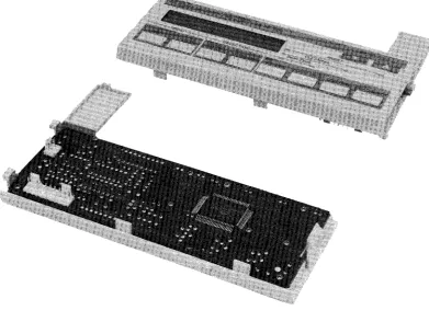
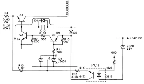
1.5.2 SEIPS/SANPSE
Board UnitThe SEIPS and SANPSE board units are the power supply units designed for 120 V and 220/240 V operation, respectively.
The SEIPS/SANPSE board unit is a power supply which supplies DC voltages to the
mechanisms and control/drive circuits, and is composed of an AC cable, switching board, and regulator circuit.
By employing a switching regulator (DC to DC converter), circuits in the SEIPS/SANPSE board were made very compact but which work very efficiently. The 494 is employed as a controller in the regulator circuit.
494