Digital Equipment Corporation
Maynard, Massachusetts
Advanced Monitor
Software System
PDP-15
ADVANCED MONITOR SOFTWARE
SYSTEM FOR
PDP-15/20/30/40
PROGRAMMER'S REFERENCE MANUAL
'. To obtain additional copies of this manual, order number DEC-15-MR2B -D from the Program library,
1st Printing January
Revised December
Copyright ~ 1970, by Digital Equipment Corporation
The material in this manual is for
informa-tion purposes and is subject to change
with-out Qotice.
The following are trademarks of Digital Equipment Corporation, Maynard, Massachusetts:
DEC
DIGITAL
PDP
FOCAL
1970
ADVANCED MONITOR SOFTWARE SYSTEM
The ADVANCED Monitor software system described in this manual may be
obtained in either of two versions: I} a standard PAGE mode system
or 2} an optional BANK mode system.
Page Mode System
The ADVANCED Monitor Page mode system loads and relocates user programs
in 4K pages and permits address modification via the index register.
The Page mode system is supplied as standard software with the
PDP-lS/20/30 and /40 systems.
NOTE
With the exception of Appendix G, or where otherwise referenced, the information presented in this manual concerns only the Page mode ADVANCED Monitor software system.
Bank Mode System
The optional Bank mode system permits direct addressing within 8K
banks, but does not permit the use of the index register for address
modification. This system is useful to the PDP-IS user who prefers
direct addressing up to 8K, or who wishes to take advantage of the
extensive library of PDP-9 programs now available from the Digital
Equipment Computer Users S~ciety (DECUS).
The Bank mode system is also available to PDP-9 users who have
equip-ment configurations comparable to those of the basic PDP-IS/20. This
enables the PDP-9 user to avail him?elf of the ma~y improvements
introduced into the PDP-IS ADVANCED Monitor software system.
The differences between the Page and Bank mode systems and procedures
for the installation of the Bank mode system are given in Appendix G.
OPTIONAL KEYBOARD MONITOR
The ADVANCED Monitor software system contains a sophisticated
inter-active keyboard/program monitor which is available in either a standard
or a "special" version. The special version (designated KMSIS) permits
Overprinting, a feature useful to FORTRAN programming, requires a
slightly larger monitor (+24
10 words). If the user desires the KMS15 version, i t must be installed into the standard system. Appendix G
contains a brief description of the KMSIS monitor and instructions for
its installation.
HOW ADVANCED SOFTWARE SYSTEMS ARE SUPPLIED
The ADVANCED Monitor software is supplied to the user (Page or Bank
mode) in the form of two DECtapes:
1) a standard system DECtape (Page or Bank mode) which contains
all programs considered as standard to the system. The
separate Page and Bank mode system DECtapes are identified
as follows:
a) Page Mode
b) Bank Mode
DEC-IS-SRZB-UC
DEC-IS-SWZA-UC
2) a peripheral DECtape common to both Page and Bank mode
systems which contains device handlers and routines for
Digital-offered optional peripherals and special programs
(e.g., KMS 15). The peripheral DECtape is identified as
DEC-IS-SZZB-UC.
OVERALL PDP-IS DOCUMENTATION STRUCTURE
A tree-type block diagram of the overall "PDP-15 Family of Manuals"
is illustrated on the following page. A brief description of the
contents and the order number of each manual shown in the diagram are
also presented.
ORGANIZATION OF PDP-IS SOFTWARE MANUALS
There are two basic categories of PDP-15 software manuals:
a. Unique, single-system manuals which contain information concerning only one of the four available PDP-IS systems. This category consists of detailed software system
descriptive manuals, each with an associated operational command summary. An example of this class of manual would be the IIpDP-IS/20 Software System" manual and its associated "PDP-lS/20 User's Guide".
-<
INSTALLATIO N MANUAL
MODULE MANUAL
HARDWARE
ACCEPTANCE TE ST PROCEDURES
INTERFACE MANUAL
PDP-15 FAMILY OF MANUALS
OPERATORS GUIDE
SOFTWARE
8/F,15/30/40
f!DP -15/20
PDP-15 110
SYSTEM USER'S ~I .... '-~f----1 GUIDE
MACRO -15
FOCAL-15
UTILITY PROGRAMS
MANUAL
FORTRAN TIL
8/15
TRANSLATOR
STATPAC-15
SCOLDS
SYSTEM REFERENCE MANUAL - Over-view of PDP-IS hardware and software systems and options; instruction repertoire, expansion features and descriptions of sys-tem peEipherals. (DEC-15-GRAZ-D)
USER'S GUIDE VOLUME 1, PROCESSOR -principal guide to 'system hardware includes system and subsystem features, functional descriptions, machine-language programming con-siderations, instruction r~per toire and system expansion data.
(DEC-15-H2DA-D)
VOLUME 2, PERIPHERALS - Features functional descriptions and pro-gramming considerations for peri-pheral devices. (DEC-15-H2DA-D)
OPERATOR'S GUIDE - Procedural data, including operator main-tenance, for using the operator's console and the peripheral de-vices associated with PDP-IS Systems. (DEC-lS-H2CA-D)
PDPlS/lO SYSTEM USER'S GUIDE -COMPACT and BASIC I/O Monitor operating procedures.
(DEC-15-GGIA-D)
PDP15/20 SYSTEM USER'S GUIDE -ADVANCED Monitor system operat-ing procedures. (DEC-15-MG2B-D)
PDP-15/20/30/40 ADVANCED MONITOR SOFTWARE SYSTEM - ADVANCED Moni-tor System descriptions; programs include system monitor and
language, utility, and applica-tion types; bperaapplica-tion, core organization, and input/output operations within the monitor environment are discussed.
(DEC-15-MR2B-D)
PDP-15/30 and 15/40 BACKGROUND/ FOREGROUND MONITOR SOFTWARE SYSTEM - Background/Foreground Monitor description, including the associated language, utility, and application programs.
(DEC-15-MR3A-D)
MAINTENANCE MANUAL VOLUME 1, PROCESSOR - Block diagram and functional theory of operation of the processor logic. Preven-tive and correcPreven-tive maintenance data . (DEC-15-HB2A-D)
VOLUME 2, PROCESSOR OPTIONS
-Block diagr~m and functional theory of operation of the processor op-tions. Preventive and corrective maintenance data. (OEC-15-HB2A-D)
VOLUME 3, PERIPHERALS (Set of Manuals - Block diagram and func-tional theory of operation of the peripheral devices. Preventive and corrective maintenance data.
(DEC-15-HB2A-D)
INSTAL4ATION MANUAL - Power
specifications, environmental con-siderations, cabling, and other information pertinent to installing PDP-IS Systems. (DEC-15-H2AA-D)
ACCEPTANCE TEST PROCEDURES -,Step-by-step procedures designed to ensure optimum POP-15 Systems' operation.
MODULE MANUAL - Characteristics, specifications, timing, and
functional descriptions of modules used in PDP-IS Systems.
(OEC-15-H2EA-D)
INTERFACE MANUAL - Information for interfacing devices to a PDP-15 System. (OEC-15-HOAA-O)
UTILITY PROGRAMS MANUAL - Utility programs common to POP-15 Monitor Systems. (OEC-15-YWZA-D)
MACRO-15 - MACRO assembly language for the PDP-IS.
(OEC-15-AMZA-O)
FORTRAN IV - PDP-IS version of the FORTRAN IV compiler language.
(DEC-15-KFZB-O)
FOCAL-IS - An algebraic interactive compiler-level language developed by Digital Equipment Corporation.
1.1 1.2 1.3 1.3.1 1.4 1.5 1.5.1 1.5.2 1.5.3 1.5.4 1.5.5 1.5.6 1.5.7 1.5.8 1.5.9 1.5.10 1.5.11 1.S.12 1.5.13 1.S.14 1.S.15 2.1 2.1.1 2.1.2 2.2 2.3 2.3.1 2.3.1.1 2.3.1.2 2.3.2 2.3.3 2.4 2.4.1 2.4.2 2.5 2.6 CONTENTS
CHAPTER 1
ADVANCED SOFTWARE SYSTEM
INTRODUCTION
HARDWARE REQUIREMENTS
MONITOR REQUIREMENTS
ADVANCED Monitor
INPUT/OUTPUT PROGRAMMING SYSTEM (lOPS)
SYSTEM PROGRAMS
FOCAL Programs
FORTRAN IV Compiler
MACRO Assembler
Dynamic Debugging Technique (DDT) Program
Text Editor Programs, EDIT and EDITVP
Peripheral Interchange Program (PIP)
Linking Loader
8 to 15 Translator (8TRAN)
System Generator
Dump Program
Library Update Program
System Patch Program
CHAIN and EXECUTE ~rograms
Source Compare Program (SRCCOM)
DECtape Copy (DTCOPY)
CHAPTER 2
THE ADVANCED MONITOR ENVIRONMENT
MONITOR FUNCTIONS
General I/O Communications
Command, Control and Data Flow
LINE BUFFERS
DATA MODES
lOPS Modes
lOPS ASCII
lOPS BINARY
Image Modes
Dump Mode
SYSTEM TABLES
Device Assignment Table (.DAT)
System Communication Table (.SCOM)
SPECIFYING DEVICES USED TO LINKING LOADER
RESERVED WORD LOCATIONS
3.1 INTRODUCTION
CHAPTER 3
SYSTEM MACROS
3.1.1 Summary of ADVANCED Monitor System MACROS 3.1.2 .INIT (Initialize)
3.1.3 .DLETE
3. 1 • 4 . RENAM 3.1.5 .FSTAT 3.1.6 .SEEK 3.1.7 .ENTER
3.1.8 . CLEAR 3 . 1. 9 . CLOSE 3.1.10 .MTAPE
3 . 1 . 11 . READ 3.1.12 .WRITE 3.1.13 .WAIT 3.1.14 .WAITR 3.1.15 .TRAN
3.1.16 .TIMER 3.1.17 .EXIT
CHAPTER
4
4.1 4.2
4.3
4.2.1 4.3.2
ADVANCED MONITOR ADVANCED MONITOR FUNCTIONS
PROGRAMMING EXAMPLE KEYBOARD COMMANDS
4.3.2.1 4.3.2.2 4.3.2.3 4.3.2.4 4.3.2.5 4.3.2.6 4.3.2.7 4.3.2.8 4.3.2.9 4.3.2.10 4.3.2.11 4.3.2.12
System Program Load Commands Special Function Commands
LOG (or L) SCOM (or S) API ON/OFF QDUMP (or tQ) HALT (or H)
INSTRUCT (or I) REQUEST (or R) ASSIGN (or A) DIRECT (or D)
NEWDIR GET (or G) CHANNEL (or C)
4.3.3 Control Character Commands
4.4 OPERATING THE ADVANcED MONITOR 4.4.1 Loading the ADVANCED Monitor
4.4.2 4.4.2.1 4.4.3 4.4.4 4.4.5 4.5 4.6 4.6.1 4.6.2 4.7 4.7.1 4.7.2 4.7.3 4.8 4.8.1 4.8.1.1 4.8.1.2 4.8.1.3 4.8.2 4.8.2.1 4.8.2.2 4.8.2.3 4.8.3 4.8.4 4.8.5 5.1 5.1.1 5.1.1.1 5.1.2 5.1.2.1 5.1.2.2 5.1.3 5.2 5.2.1 5.2.2 5.2.3
System Generation
DECtape or DECdisk Systems
Assigning Devices
Loading Programs in the ADVANCED Monitor Environment
Error Detection and Handling
BATCH PROCESSING
DECTAPE FILE ORGANIZATION
Non-File-Oriented DECtape
File-Oriented DECtape
RF15 DECDISK
General Description
File Structure
Disk File Protection
MAGNETIC TAPE
File Organization
Non-File Structured Data Recording
File-Structured Data Recording
Block Format
File Identification and Location
Magnetic Tape File Directory
User-File Labels
File-Names in Labels
Continuous Operation
Storage Retrieval on File-Structured Magnetic
Magnetic Tape Dump (MTDUMP) utility Program
CHAPTER 5
I/O DEVICE HANDLERS
DESCRIPTION OF I/O HARDWARE AND API SOFTWARE LEVEL HANDLERS
I/O Device Handlers
Setting Up the Skip Chain and API (Hardware) Channel Registers
API Sqftware Level Handlers
Tape
Setting Up API Software Level Channel Registers
Queueing
Standard API Channel/Priority Assignments
WRITING SPECIAL I/O DEVICE HANDLERS
Discussion of Example A by Parts
Example A, Skeleton I/O Device Handler
Example B, Special Device Handler for AFOIB A/D Converter
5.3 5.3.1 5.3.2 5.3.3 5.3.4 5.3.5 5.3.6 5.3.7 5.3.8 5.3.9 5.3.10 5.3.11 5.3.12 5.3.13 5.3.14 5.3.15 5.4 5.4.1 5.4.1.1 5.4.1.2 5.4.1.3 5.4.1.4 5.4.1.5 5.4.1.6 5.4.1.7 5.4.2 5.4.2.1 5.4.2.2 5.4.2.3 5.4.2.4 5.4.2.5 5.4.2.6 5.4.2.7 5.4.2.8 5.4.3 5.4.3.1 5.4.3.2 5.4.3.3 5.4.3.4 5.4.4 5.4.4.1 5.4.4.2 5.4.4.3
DEVICE HANDLERS ACCEPTABLE TO SYSTEM PROGRAMS,
FORTRAN IV (F 4 )
MACRO-15
FOCAL
EDIT and ECITVP
Linking Loader and DDT
PIP (Peripheral Interchange Program)
SGEN (System Generator)
PATCH
UPDATE
DUMP
CHAIN
EXECUTE
SRCCOM (Source Compare)
DTCOPY (DECtape Copy)
8TRAN (PDP-8 to PDP-IS Translator)
SUMMARY OF STANDARD I/O HANDLER FEATURES
TTA (Teletypewriter)
General Description
Functions
Legal Data Modes
Function Characters
Program Control Characters
Unrecoverable Errors
Restriction
PP (Paper Tape Punch)
General Description
Functions
Legal Data Modes
Vertical Control Characters (lOPS ASCII only)
Horizontal Control Characters
Recoverable Errors
Unrecoverable Errors
Restriction
PR (Paper Tape Reader)
General Description
Functions
Legal Data Modes
Unrecoverable Errors
DT (DECtape)
General Description
Functions
Legal Data Modes
5.4.4.4 5.4.4.5 5.4.5 5.4.5.1 5.4.5.2
5.4.5.3
5.4.5.4 5.4.5.5 5.4.6 5.4.6.1 5.4.6.2 5.4.6.3 5.4.6.4 5.4.6.5 5.4.7 5.4.7.1 5.4.7.2 5.4.7.3 5.4.7.4 5.4.7.5 5.4.7.6 5.4.8 5.4.8.1 5.4.8.2 5.4.8.3 5.4.8.4 5.4.8.5 5.4.9 5.4.9.1 5.4.9.2 5.4.9.3 5.4.9.4 5.4.9.5 5.4.9.6 5.4.9.7Recoverable Errors
Unrecoverable Errors
RF (RF15 DECdisk)
General Descript~on
Functions
Legal Data Modes
Recoverable Errors
Unrecoverable Errors
MT (Magnetic Tape)
General Description
Functions
Legal Data Modes
Recoverable Errors
Unrecoverable Errors
LPA. (Line Printers LPl5C and LPl5F)
General Description
Functions
Legal Data Modes
Carriage Control Characters
Recoverable Errors
Unrecoverable Errors
CDB. (CR03B Card Reader)
General Description
Functions
Legal Data Modes
Recoverable Errors
Unrecoverable Errors
VPA. (VP15A Storage Tube Display)
General Description
Functions
Legal Data Modes
Data Mode Functions
Special Characters
Printing Rules
Unrecoverable Errors
APPENDIX A
APPENDIX B
APPENDIX C
APPENDIX D
Appendix E
Appendix F
APPENDIX G
INDEX
PDP-IS lOPS ASCII Character Set
PDP-IS ASCII/Hollerith Correspondence
ADVANCED Monitor Error Printouts
Linking Loader and System Loader Errors
lOPS Errors
Summary of Keyboard Commands
Optional ADVANCED Software
PDP-IS ADVANCED Monitor Reference Card (Tear-out)
1-1 1-2 2-1 2-2 2-3 2-4 2-5 2-6 2-7 2-8 2-9 4-1
4-2
4-34-4
4-5a 4-5b 4-6a 4-6b 5-1 5-2 5-3 5-4 2-1 2-2 2-3 2-4 4-1 4-2 FIGURESADVANCED Monitor
PDP-15/20 System Equipment Configuration (Basic)
General I/O Communication in Monitor Environment
Command, Control and Data Flow in Monitor Environment
ADVANCED Monitor Commands and Function Codes
Line Buffer Structure
Format of Header Word Pair
lOPS Mode Data on Paper Tape
5/7 ASCII Packing Scheme
Image Mode Data on Paper Tape
lOPS ASCII and Image Alphanumeric Data in Line Buffers and on Mass Storage Devices
ADVANCED Monitor System Memory Maps
DECtape Directory
DECtape File Bit Map Blocks
Block Format, File-Structured Mode
Format of the File Directory Data Block
Format of File-structured Tape
User-File Header Label Format
User-File Trailer Label Format
CAL Handler Functions
CAL Entry to Device Handler
PI and API Entries to I/O
.
Structure of API Software Level Handler
TABLES
Maximum Line Buffer Sizes
Input/Output Data Mode Terminators
System Communication Table (.SCOM) Entries
Reserved Address Locations
Control Character Commands
Function of .DAT Slots in the ADVANCED MOnitor System
CHAPTER 1
ADVANCED SOFTWARE SYSTEM
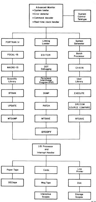
1.1 INTRODUCTION
The ADVANCED Software System is a complete integrated system of programs
for the preparation, compilation, assembly, debugging, and operation of
user programs. A diagram illustrating the structure of the ADVANCED
software system is shown in Figure 1-1. As shown, this software system
includes:
a. Compiler and assembly language programs
b. A large group of progran1ffiing and operational aid (utility) programs
c. A versatile and flexible Input/Output Programming System (lOPS)
d. A sophisticated interactive keyboard/program monitor which permits device-independent programming and automatic
creation, calling, and loading of programs.
Upwards-compatibility exists between all PDP-IS Monitor Systems
(e.g., programs prepared for the Basic I/O Monitor may be run in the
ADVANCED system environment) .
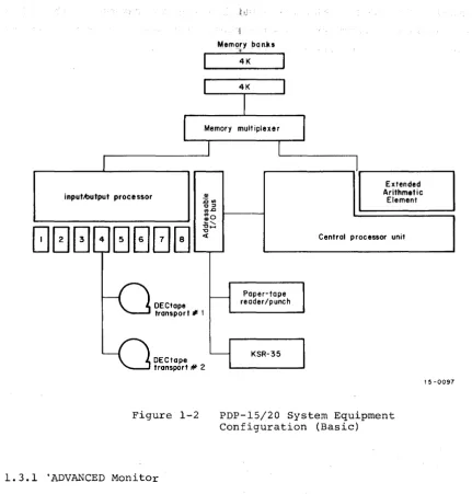
1. 2 HARD~vARE REQUIREMENTS
The minimum equipment configuration for the employment of the ADVANCED
Software System is that of the Basic 15/20 system a~ illustrated in
Figure 1-2.
1.3 MONITOR SYSTEMS
Monitor systems simplify the handling of input/output functions and
facilitate the creation, debugging, and use of USER programs. They
all~w overlapped input/output and computation, simultaneous operation
of a number of asynchronous peripheral devices, and (in the case of the
ADVANCED Monitor) device-independent programming, while freeing the
user from the need to create device-handling subroutines. The Monitor,
operating in conjunction with the Input/Output Programming System (lOPS)
provides a complete interface between the user's programs and the
Advanced Monitor • System loader
• Error detector
• Command decoder
• Real-time clock handler
I/O Processor and Interrupt Handler
Figure 1-1 ADVANCED Iv\onitor
System Control Teletype
[image:15.618.145.463.44.708.2]inputAlutput proce ssor
DECtape transport" 1
DECtope transport # 2
Figure 1-2
1.3.1 'ADVANCED Monitor
Mem()ry banks
*
4K
Paper-tope reader/punch
KSR-35
Extended Arithmetic
Element
Central processor unit
PDP-15/20 System Equipment Configuration (Basic)
15-0097
The ADVANCED Monitor Software System includes all of the facilities of
the BASIC I/O Monitor (Paper Tape) plus routines to accept and act
upon teleprinter keyboard commands, the ability to dynamically modify
I/O device assignments for a program, and the facilities for automatically
storing, calling, loading, and executing system and user programs.
with the ability to alter I/O assignments, this Monitor brings true
device independence to the user. Programs may be modified simply and
quickly to operate on any configuration, and additions to (or deletions
from) existing hardware need not result in program reassembly or
recom-pilation.
The Monitor also frees the user from the problems of tape or card
handling. Programs can be created, stored, retrieved, loaded, debugged,
and operated at the keyboard console. Both system and user programs
[image:16.615.88.520.31.482.2]commands. The Monitor also has a batch processing capability that allows
user commands to originate from the paper tape reader or card reader
in-stead of from the teleprinter, thus permitting many programs to be run
without operator intervention.
1.4 INPUT/OUTPUT PROGRAMMING SYSTEM (lOPS)
The Input/Output Programming System (lOPS) consists of an I/O control
routine (CAL handler) and individual hardware device handling routines
(device handlers) that process file and data level commands to the device.
These handlers exist for all standard peripherals (see Section 5.4).
The CAL handler accepts user program commands and transfers control to
the appropriate device handlers. These device handl~rs are responsible
for transferring data between the program and I/O devices, for initiating
the reading or writing of files, for opening and closing files, and for
performing all other functions peculiar to a given hardware device.
They are also responsible for ignoring functions which they are incapable
of handling; for example, trying to rewind a card reader. All device
handlers operate either with or without the Automatic Priority Interrupt
(API) option.
1.5 SYSTEM PROGRAMS
In addition to lOPS and the ADVANCED Monitor, the ADVANCED Software System
contains the following language and utility programs:
FOCAL - Algebraic Language Interpreter (DEC-lS-KJZB-D)
FORTRAN IV - Compiler, Object Time System, and Science Library (DEC-lS-KFZB-D)
MACRO-IS - PDP-IS Assembler (DEC-lS-AMZB-D)
DDT - Dynamic Debugging Technique
EDIT - Text Editor
EDITVP - Text Editor for VPlSA Storage Tube Display
PIP - Peripheral Interchange Program
Linking Loader - Loads Relocatable Programs
CHAIN - Program to Construct System of Core Overlays (DEC-IS-YWZA-D)
EXECUT - Program to Supervise Execution of CHAIN Built Overlay System
SGEN - System Generator
DUMP - Dump Program
PATCH - System Patch Program
SRCCOM - Sou'rce Compare Program
DTCOPY - High-Speed 8K DECtape Copy Program
The following special purpose utility programs are also available:
RFSAVE - DECdisk/DECtape Save
MTSAVE - DECdisk/Magtape Save
MTDUMP - Magnetic Tape Dump
1.5.1
FOCAL Programs}
(DEC-lS-YWZA-D)FOCAL (Formulating On-line Calculations in Algebraic Language) operates
in on-line conversational mode, using natural language and arithmetic
terms to establish a simplified environment for the computer-aided
solution of business and scientific 'arithmetic problems. Included in
FOCAL are such features as:
1. Device independence;
2. Linkage to assembly language (MACRO) routines to establish a user library of commonly used functions;
3. Use of COMMON to facilitate chaining in the same manner as FORTRAN IV.
1.5.2 FORTRAN IV Compiler
The PDP-IS FORTRAN IV compiler is a two-pass system that accepts
state-ments written in the FORTRAN IV language and produces a relocatable
object program capable of being loaded by the Linking Loader. It is
completely compatible with USA FORTRAN IV, as defined in USA Standard
X3.9-1966, with the exception of the following features, which were
modified to allow the compiler to operate in 8192 words of core storage:
a. Complex arithmetic is not legal.
b. Adjustable array dimensions are not allowed at source level, but may be implemented by calling dimension-adjustment subroutines provided in the Science Library.
c. Blank Cornmon is treated as named Common except when the object program is used in chaining.
d. The implied DO feature is not included for the DATA statement.
e. Specification statements must be strictly positioned and ordered~
The FORTRAN IV compiler operates with the program interrupt or API
facilities enabled. It generates programs that operate with the
Program Interrupt (PI) or Automatic Priority Interrupt (API) enabled,
and can work in conjunction with assembly language programs that
recognize and service real-time devices. Subroutines written in either
FORTRAN IV or MACRO-IS assembly language can be loaded with and called
by FORTRAN IV main programs. Comprehensive source language diagnostics
are produced during compilation, and a symbol table is generated for
There are three versions of the FORT~ IV compiler: (1) F4, the basic
compiler; (2) F4I, a compiler which permits DECtape I/O in an 8K system;
and (3) F4S, a more powerful version of F4 which has fewer restrictions
and an expanded diagnostic capability.
1.5.3 MACRO Assembler
The MACRO Assembler provides users with highly sophisticated macro
generating and calling facilities within the context of a symbolic
assembler.
Some of the prominent features of MACRO include:
a. The ability to:
(1) define macros
(2) define macros within macros (nesting)
(3) redefine macros (in or out of macro definitions)
(4) call macros within macro definitions
(5) have macros call themselves {recursion)
(6) combine three input files for one assembly
b. Conditional assembly based on the computational results of symbols or expressions
c. Repeat functions
d. Boolean manipulation
e. Optional octal, symbolic, and cross-reference listings
f. Two forms of radix control (octal, decimal) and two text modes (ASCII and 6-bittrimmed ASc:II)
g. Global symbols for easy linking of separately assembled programs
h. Choice of output format: relocatable, absolute binary (check summed), or full binary capable of being loaded via the hardware READIN switch
i. Ability to call input/output system macros that expand into lOPS calling sequences
A shorter version of the assembler (MACROI) is available for users
with 8K systems which permits DECtape input and output.
1.5.4 Dynamic Debugging Technique (DDT) Program
DDT provides on-line debugging facilities within the ADVANCED Software
System, enabling the user to load and op~rate his program in a
real-time environment while maintaining strict control over the running of
each section. DDT allows the operator to insert and delete breakpoints,
examine and change registers, patch programs, and search for specific
The DDT breakpoint feature allows the insertion and simultaneous use of
up to four breakpoints, any or all of which may be removed,with a
I
single keyboard command. The search facility allows the operator to
specify a search through any part ~r all of an object program with a
printout of the locations of all r~gisters that are equal (or unequal)
to a specified constant. This search feature also works for portions
of words as modified by a mask. with DDT, registers may be examined and
modified in either instruction format or octal code, and addresses may
be specified in symbolic relative, octal relative, or ~ctal absolute.
Patches may be inserted in either source language or octal.
1.5.5 Text Editor Programs, EDIT and EDITVP
The Text Editor of the ADVANCED Software System provides the ability
to read alphanumeric text from any input device (paper tape reader,
card reader, disk, DECtape, magnetic tape, etc.), to examine and correct
it, and to write i t on any output device. It can also be used to
create new symbolic programs.
The Editor operates on lines of symbolic text delimited by carriage
return (CR) or ALT MODE characters. These lines can be read into a
buffer, selectively examined, deleted or modified, and written out.
New text may be substituted, inserted, or appended.
The program EDITVP is similar to EDIT except that i t permits the text
to be displayed on the VPlSA storage tube.
1.5.6 Peripheral Interchange Program (PIP)
The primary function of PIP is to facilitate the manipulation and
transfer of data files from any input device to any output device. It
can be used to refresh mass storage file directories; list file
directory contents; delete, insert, segment, or combine files; perform
code conversions; transfer files; or copy the entire contents of mass
storage units.
1.5.7 Linking Loader
The Linking Loader loads any FORTRAN IV or MACRO object program which
exists in relocatable format (or absolute format, if pseudo-ops .ABS
and .FULL are not used). Its tasks include loading and relocation
of programs, loading of called subroutines, retrieval and loading of
implied subroutines, and building and relocation of the necessary
1.5.8 8 to 15 Translator (8TRAN)
i
This program is used as an aid in tra~slating programs written for the
Digital PDP-8 computer into MACRO-IS form. The translator does not
necessarily produce an executable program, but translates a major portion
of the PDP-~ code into equivalent MACRO-IS code and indicates those areas
of the 8 program which must be reviewed and processed by t~e programmer.
1.5.9 System Generator
The System Generator (SGEN) is a standard system program used to create
new system tapes. With it, the user can tailor his system to his
installation's needs and specify standard input and output devices,
memory size, and special I/O and central processor options present.
1.5.10 Dump Program
This system program gives the user the ability to output on any listing
device specified core locations that have been preserved on a bulk
storage file via the CTRL Q Keyboard Monitor dump command. It also
provides the ability to dump areas of mass storage (e.g., a DECtape
block) onto any listing device.
1.5.11 Library Update Program
This system program gives the user the capability to examine and update
the binary library files on mass storage devices.
1.5.12 System Patch Program
The System Patch Program is used to make corrections to the binary
version of non-relocatable system programs on the system device, to
examine and change any word in any DECtape or DECdisk block, or to
convert relocatable binary programs into system programs (SYS files).
1.5.13 CHAIN and EXECUTE Programs
The programs CHAIN and EXECUTE provide the user with the ability to
construct and run a system of core overlays in the ADVANCED Monitor
environment.
1.5.14 Source Compare Program (SRCCOM)
The SRCCOM program compares any two symbolic programs (IOPS ASCII) and
indicates their differences. This program is useful for program
identification and/or verification, proofing an edited program,
com-parison of old and new versions of the same program, etc.
1.5.15 DECtape Copy (DTCOPY)
This program, designed for 8K system users, permits high speed copying
CHAPTER 2
THE ADVANCED MONITOR ENVIRONMENT
2.1 MONITOR FUNCTIONS
The ADVANCED Monitor simplifies the task of programming I/O functions
by providing an interface between system or user programs and the
external world of I/O devices. The Monitor, by means of lOPS and
Program Interrupt (PI) or optional Automatic Program Interrupt (API),
permits simultaneous operation of multiple I/O devices along with
over-lapping computations.
2.1.1 General I/O Communication
The general conununication required to accomplish an I/O task is the same
for all three Monitor systems (see Figure 2-1). A system or user
program initiates an I/O function by means of a Monitor conunand (system
macro), which is interpreted by a CAL handlerl within the Monitor as a
legitimate I/O call. The I/O call includes a logical I/O device
number as one of its arguments. The Moni tor, establishes the logical/
physical I/O device association by means of its Device Assignment Table
(.DAT). When this has been accomplished, the Monitor passes control to
the appropriate device handler subroutine to initiate the I/O function
DATA
~
~
VIA CAL VIA PI
VIA CAL HANDLER I/O DEVICE HANDLER OR A PI
SYSTEM OR MONITOR
INITIATION !INTERRUPT
I/O DEVICE USER PROGRAM
i
CONTROL RETURN~
Figure 2-1
~
IGeneral I/O Communication in Monitor Environment
lRefer to the PDP-15 Users' Handbook Vol. 1, (DEC-15-H2DA-D) for a description of the CAL handler.
and return control to the system or user program. The system or user
program retains control until an interrupt (PI or API) occurs, at which
time i t relinquishes control to the device handler to perform and/or
complete the specified I/O function. Computation or other processing
can be performed by the system or user program while waiting for an
interrupt. This feature allows the programmer to make optimum use of
available time.
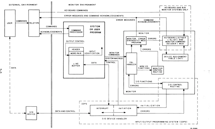
2.1.2 Command, Control, and Data Flow
Figure 2-2 illustrates the data flow and general organization of the
ADVANCED Monitor. As shown, the user can initiate a command via the
teleprinter.
In the ADVANCED Monitor environment, an expanded set of keyboard
com-mands can be interpreted by a Keyboard Listener (.KLIST) and act~d upon
by a Monitor Command Decoder (.MCD). This feature greatly extends the
capabilities of the Monitor and provides the user with a large
repertoire of keyboard commands. The .KLIST and .MCD programs are
nonresident in the sense that they are overlaid by user and system
programs.
Each system or user program must internally set up line buffers (except
when using Dump mode, discussed later) to be used in transmitting data
to or from the external environment. Each line buffer of n words
con-sists of a two-word header (referred to as a header word pair) and n-2
words of data. The system or user program can exercise control on
out-put by mOdifying the header word pair, or i t can verify on inout-put by
examining the header word pair. The use of line buffers is discussed
in more detail later in this chapter.
ADVANCED Monitor I/O commands (system macros1
) are written as part of
the system or user program. In FORTRAN IV source programs, these
com-mands are in the form of READ and WRITE statements (refer to the
FORTRAN IV Manual, DEC-15-KFZA-D). These statements are translated by
the compiler into the proper calling sequences for the FORTRAN Object
Time System which provides the required monitor calls at execrition time.
In MACRO source programs, Monitor I/O commands are written as system
macros within the system or user program. These system macros are
expanded at assembly time, and include a CAL initiated monitor call
that contains the logical device number as one of the arguments.
EXTERNAL ENVI RONMENT USER
t
I
I
I
I
I
I
N
I
DATAI
I WI
I
I
I
I
I
I
I
I
L - -
-.j
DEl:~CE ~
MONITOR ENVIRONMENT
KEYBOARD COMMANDS
ERROR MESSAGES AND COMMAND ACKNOWLEDGEMENTS
I
-;EYBOARD ~DBiAl
I MONITOR SYSTEMS ONLY
I
II
ERROR MESSAGES COMMAND
I
ACKNOWLEDGEMENTSI
COMMANDSI
ACKNOWLEDGEMENTS PROCESSOR COMMANDSYSTEM
OR USER
PROGRAM MONITOR
I
-OUTPUT CONTROL
----HEADER WORD PAIR
LINE BUFFER
INPUT
t
VERIFICATIONJ
DATA
MONITOR COMMANDS (SYSTEM MACROS)
-
CONTROLKEYBOARD LISTNER
I
(.KLIST) ANDI
MONITOR COMMAND MONITOR ERRORI ERRORSDIAGNOSTIC(.MED) -PROGRAM
1~
I
DECODER(MCD)I
CAL HANDLER
I
L
_____
-.J
NON I/O I FUNCTIONS MONITOR
CONTROL ROUTINE
DEVICE ASSIGNMENT TABLE LDAT)
I/O FUNCTIONS
1 - - - 1 '
DATA AND CONTROL
ERRORS
MONI TOR
1 . - - - -
-~----~----lOPS
1
~
I
-.J
I
INITIALIZATIONINTERRUPT INITIATION
I
4 .. ERRORS
I
I
I/O DEVICE HANDLERI/O CONTROL ROUTINE
&
,.
I
I
I
I
I
I
I
I
I
I
L ___________ _
INPUT/OUTPUT PROGRAMMING SYSTEM (lOPS)J
-15-0095
[image:24.793.37.773.64.506.2]At execution time, monitor calls are processed by the CAL Handler within
the Monitor. Non-I/O functions are then further processed by the Monitor
Control Routine, and I/O functions are processed by the I/O Control
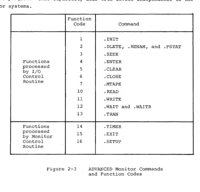
Routine (see Figures 2-2 and 2-3). A complete description of each of
these commands is given in Chapter 3. If the original conulland involved
is an I/O function, the I/O Control Routine checks the Device
Assign-ment Table to associate the logical I/O device (specified by the system
macro) to a physical I/O device.
In the ADVANCED Monitor environment, device associations can be
per-manently modified at System Generation time, or dynamically modified
by means of the ASSIGN keyboard command just prior to loading a system
or user program. This capability adds true device independence to the Monitor systems.
Function Code
1
2
3
Functions 4
processed
5
by I/O
Control 6
Routine
7 10 11
12
13
Functions 14
processed
15 by Monitor
Control 16
Routine
Figure 2-3
Command
.INIT
.DLETE, .RENAM, and .SEEK
.ENTER
. CLEAR
. CLOSE
.MTAPE
. READ
.WRITE
.WAIT and .WAITR
.TRAN
.TIMER
.EXIT
. SETUP
ADVANCED Monitor Commands and Function Codes
. FSTAT
When the logical/physical I/O device association has been established,
the Monitor passes control to the appropriate I/O device handler, which
initializes itself, initiates I/O, and returns control to the system or
user program. As mentioned previously, the system or user program
re-tains control until the specified device causes an interrupt (PI or API) .
At this point, i t relinquishes control to t~e device handler to continue
[image:25.615.113.526.230.626.2]returned to the system or user program at the point where i t was
inter-rupted. The system or user program, by means of a .WAIT (or .WAITR)
system macro (described in Chapter 3), can determine whether an input
or output operation has been completed. If the transfer of data from
or to the system or user program line buffer has been completed, program
execution continues; if the transfer has not been completed, control is
returned to the .WAIT macro or to the address specified in the .WAITR.
Additional buffering is provided by the individual device handlers as
required. All device handlers are non-resident in the sense that only
those handlers required by the system or user program are loaded into
core.
2.2 LINE BUFFERS
As mentioned in the preceding general description of the Monitor
environment, each system or user program must internally set up line
buffers to be used in transmitting data to or from the external
environ-ment. An exception to this rule is when data is transmitted in the
Dump mode (described in paragraph 2.3.3) or when the .TRAN command is
used (see paragraph 3.1.15). Each line buffer of n words (always even)
should be set up to consist of a two-word header (termed a header word
pair) followed· by n-2 words of data, as shown in Figure 2-4.
Word 0 First Word of Line Buffer Header Word 1 Second Word of Line Buffer Header Word 2 First Word of Data Area
~
~
Word n-l Last Word of Data Area
Figure 2-4 Line Buffer Structure
A system or user program should contain at least one line buffer for
each device that is to be used simultaneously. This buffer is used to
set up output lines before transmittal to an output device, or to
receive input lines from the associated input device. The Monitor
accepts commands (system macros) from system or user programs to initiate
input to the line buffers and to write out the contents of line buffers.
Complete descriptions of these commands are given in Chapter 3. Line
buffers are internal to, and must be defined by, each system or user
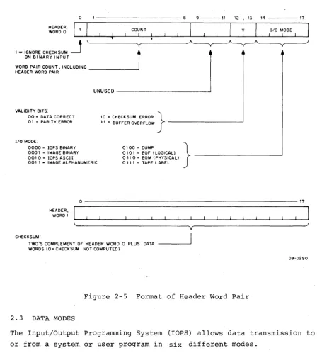
program. The header word pair within a line buffer is detailed in
Figure 2-5 and should be studied carefully. The .BLOCK pseudo operation
allow referencing by individual .READ and .WRITE macros. For example:
LINEIN
LINOUT
.DEC
.BLOCK 52
.BLOCK 52
/creates 52-word line /buffer named LINEIN. /creates 52-word line /buffer named LINOUT.
Before output, the user must set the appropriate word pair count in
bits I through 8 of word zero in the line buffer if i t has not already
been set by a device handler on input. This count overrides the word
count passed to lOPS by the .WRITE macro. (The word count must still
be specified in the .WRITE macro for each data mode; however, i t only
has meaning in Dump mode in which there is no header word pair.) In
lOPS binary mode (discussed in Paragraph 2.3.1.2), bits 9 through 11
should be set to 101 if the output will ultimately be on cards. The
checksum word, the second word in the header, need not be set by the
user since checksums are computed by lOPS.
Before input, the user should not be concerned with the header word
pair since they will be set by lOPS to enable the user to determine
what has happened after input has termina~ed.
On input, the word count specified in the .READ macro is used by lOPS
to determine the maximum number of locations to be occupied by the data
being read. If the word count is exceeded before input is terminated,
or if there is a parity or checksum error, lOPS sets the appropriate
validity bits in header word 0 to indicate the error.
After input, the user should check the validity bits in word 0 of the
line buffer header to determine if the data was read without error.
If multiple errors are detected, priority is given to a parity error
over a checksum error. lOPS ignores checksum errors on binary input if
bit 0 of word 0 of the line buffer header is set to 1. lOPS sets the I/O mode bits (bits 14 through 17 of word 0 of the line buffer header)
to: 6 (0110
2) if i t senses a physical medium (such as end-of-tape in the paper-end-of-tape reader), or 5 (0101
2) if i t senses a logical end-of-files.
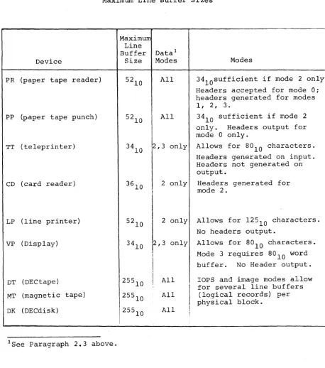
When choosing a word count (that is, the maximum line buffer size) to
specify in system macros, both the set of; possible devices and the mode
of data transmission must be considered. The maximum line buffer sizes
(including 2-word header) for standard peripheral devices, along with
o - - - 8 9 - - - 1 1 12,13 1 4 - - - - 1 7
HEADER,
WORD 0 COUNT I
1 ,. IGNORE CHECKSUM
~
r
ON BINARY INPUTWORD PAIR COUNT. INCLUDING _ _ _ _ _ _ ----J HEADER WORD PAIR
VALIDITY BITS:
00 = DATA CORRECT 01 = PARITY ERROR
UNUSED---~
10 = CHECKSUM ERROR }
" = BUFFER OVERFLOW - - - '
1/0 MODE
I
110 MODE:
0000 = lOPS BINARY 000' = IMAGE BINARY 00' 0., lOPS ASCI I 001 I • IMAGE ALPHANUMERIC
0100 = DUMP 0' 0 I = EOF (LOGICAL) 0" 0" EOM (PHYSICAL)
0' I , = TAPE LABEL
}
-HEADER, WORD'
0 - - - 1 7
~~---___________ ~yr---~J
CHECKSUM"
TWO'S COMPLEMENT OF HEADER WORD 0 PLUS DATA WORDS (0 = CHECKSUM NOT COMPUTED)
09-0290
Figure 2-5 Format of Header Word Pair
2. 3 DATA MODES
The Input/Output Programming System (rOPS) allows data transmission to
or from a system or user program in six different modes.
Mode Code1
rops Binary 0
rmage Binary 1
rops ASCII 2
rmage Alphanumeric 3
Dump
4
9-Channe1 Dump 5 (Magtape only; see sections 5.3.10, 5.4.6, and 5.4.6.3 (f).)
1 Bi ts 14' through 17 of Header Word 0, specified by system macro and
[image:28.615.80.536.52.557.2]Table 2-1
Maximum Lihe Buffer Sizes
Device
PR (paper tape reader)
PP (paper tape punch)
TT (teleprinter)
CD (card reader)
LP (line printer)
VP (Display)
DT (DECtape)
MT (magnetic tape)
DK (DECdisk)
lSee Paragraph 2.3 above.
Maximum Line Buffer
Size
Datal Modes
All
All
2,3 only
3610 2 only
!
52
10 2 only
3410 2,3 only
I
1
I
255
10
I
1 All255
10 All
25510 All
I
I
I
I
Modes
34l0sufficient if mode 2 only.
Headers accepted for mode 0: headers generated for modes 1, 2, 3.
34
10 sufficient if mode 2 only. Headers output for mode 0 only.
Allows for 80
10 characters. Headers generated on input. Headers not generated on output.
Headers generated for mode 2.
Allows for 12510 characters.
No headers output.
Allows for 8°10 characters. Mode 3 requires 8010 word buffer. No Header output.
rops
and image modes allow for several line buffers [image:29.623.73.531.67.584.2]2.3.1 lOPS Modes
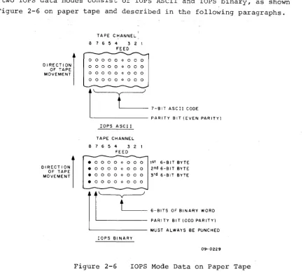
The two
rops
data modes consist ofrops
ASCII and lOPS binary, as shownin Figure 2-6 on paper tape and described in the following paragraphs.
DIRECTION) OF TAPE MOVEMENT
DIRECTION) OF TAPE MOVEMENT
TAPE CHANNEL 8 1 6 5 4 3 2 I
FEED
0 0 0 0 0 0 0 0 0
o 0 0 0 0 0 0 0 0 0 0 0 0 0 0 0 0 0
o 0 0 0 0 0 0 0 0
r---""f.---'J
l
'---
1-BIT ASCII CODE ' - - - PARITY BIT (EVEN PARITY)lOPS ASCI I
TAPE CHANNEL 8 1 6 5 4 3 2 I
FEED
• 0 0 0 0 0 0 0 0 1st 6- B IT BYTE • 0 0 0 0 0 0 0 0 2 nd 6-BIT BYTE • 0 0 0 0 0 0 0 0 3 rd 6-91T BYTE . 0 0 0 0 0 0 0 0
r
t )
6-BITS OF BINARY WORO PAR I TY BIT (000 PAR ITY) ' - - - MUST ALWAYS BE PUNCHEDrops 91 NARY
09- 0229
Figure 2-6 lOPS Mode Data on Paper Tape
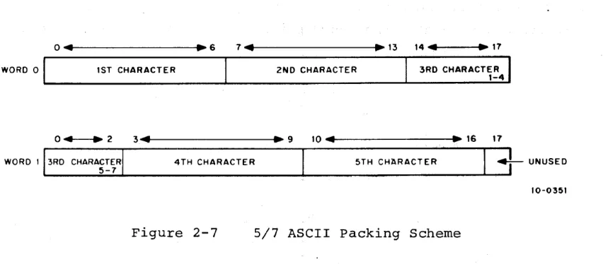
2.3.1.1 lOPS ASCII - Seven-bit ASCII is used by lOPS to accommodate the
entire 128-character revised ASCII set (Appendix A). All alphanumeric
data, whatever its original form on input (ASCII, Hollerith, etc.) or
final form on output, is converted internally and stored as 5/7 ASCII.
"5/7 ASCII" refers to the internal packing and storage scheme. Five
7-bit ASCII characters are packed in two contiguous locations, as
shown in Figure 2-7, and can be stored as binary data on any bulk
storage device. Input requests involving lOPS ASCII should be made
with an even word count to accommodate the paired input.
ASCII data is ordinarily input to or output from lOPS via the
tele-printer or paper tape, although i t may exist in 5/7 ASCII form on any
mass storage device. lOPS ASCII is defined as a 7-bit ASCII character
with even parity in the eighth (high order) bit, in keeping with USA
standards. lOPS performs a parity check on input of lOPS ASCII data
[image:30.615.111.544.55.449.2]WORD 0
04
1ST CHARACTER
~ 6 7 ... 41---.~ 13 14 ... 41---t.~ 17
2ND CHARACTER 3RD CHARACTER 1-4
0 + - - + 2 3 ... 4t---.~ 9 10 ... 41---t~~ 16 17
WORD I 3RD CHARACTER
5-7 4TH CHARACTER
5TH CHaRACTER ~ UNUSED 10-0351
Figure 2-7 5/7 ASCII packing Scheme
Non-parity lOPS ASCII occurs in data originating at a Model 33, 35,
or 37 Teletypel
, without the parity option. This data always appears
with the eighth (high order) bit set to 1. Apart from parity checking,
the lOPS routines handle lOPS ASCII and non-parity lOPS ASCII data
identically.
An alphanumeric line consists of an optional initial form control
character (line feed, vertical tab, or form feed), the body of the
line, and a carriage return (CR) or ALT MODE. CR (or ALT MODE) is a
required line terminator in lOPS ASCII mode. Control character scanning
is performed by some device handlers for editing or control purposes.
(See Section 5.4 for effects of control characters on specific devices.)
2.3.1.2 lOPS Binary - lOPS Binary data is blocked in an even number of
words, with each block preceded by a two-word header. On paper tape
(see Figure 2-6), lOPS binary uses six bits per frame, with the eighth
channel always set to 1, and the seventh channel containing the parity
bit (odd parity) for channels 1 through 6 and channel 8. The parity
feature supplements the checksumming as a data validity provision in
paper tape lOPS binary.
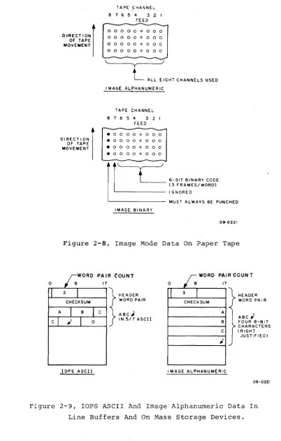
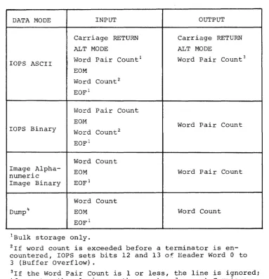
2.3.2 Image Modes
Image Mode data is read, written, and stored in the binary or
alpha-numeric form of the source or terminal device, one character per word,
as shown in Figures 2-8 and 2-9. No conversion, checking, or packing
is permitted.
[image:31.612.91.517.50.237.2]DIRECT ION) OF TAPE MOVEMENT
TAPE ,CHANNEL 8 7 6 5 4 3 2 1
FEED
o 0 0 0 0
0 0 0 0 0 0 0 0
0 0 0 0 0 0 0 0
o 0 0 0 0
'~----~yr---~
L
ALL EIGHT CHANNELS USED01 RECTI ON )
OF TAPE MOVEMENT
I MAGE ALPHANUMER IC
TAPE CHANNEL 8 7 6 5 4 3 2 1
FEED
...
-• 0 0 0 0 0 o 0 0
•
o 0 0 o 0 o 0 0. 0 0 0 0 o 0 0 0
. 0 0 0 0 0 o 0 0
I~
~
IMAGE BINARY6-BIT BINARY CODE (3 FRAMES/WORD) IGNORED
MUST ALWAYS BE PUNCHED
09-0221
Figure 2-8, Image Mode Data On Paper Tape
PAIR COUNT
17
... _ _ C...,H,...E_C_K S_U_M--._--t
f
~ ~ ~ ~
E~A
I RC ABC;' C IN 5/7 ASCII
lOPS ASCII
r.
WORD PAIR COUN T0 17
I
3I
CHECK SUMA B C
;
I MAGE ALPHANUMERI C
HEADER WORD PAIR
ABC; FOUR 8-BIT CHARACTERS ( RIGHT
JUSTIFIED)
09-0221
Figure 2-9, lOPS ASCII And Image Alphanumeric Data In
[image:32.617.120.523.48.680.2] [image:32.617.188.501.59.453.2]2.3.3 Dump Mode
Dump mode data is always binary. Dump mode is used to output from or
load directly into any core memory area, bypassing the use of line
buffers. Each dump mode statement has arguments defining the core
memory area to be dumped. Dump mode is normally used with bulk storage
devices, although i t is also possible to use i t with paper tape output
and input.
Table 2-2
Input/Output Data Mode Terminators
DATA MODE INPUT OUTPUT
Carriage RETURN Carriage RETURN
ALT MODE ALT MODE
lOPS ASCII Word Pair Count
1 Word Pair Count3
EOM
Word Count2
EOFl
Word Pair Count
EOM Word Pair Count
lOPS Binary Word Count2
EOFl
Word Count Image
Alpha-EOM Word Pair Count
numeric
Image Binary EOFl
Word Count
Dump 4 EOM Word Count
EOF1
IBu1k storage only.
2If word count is exceeded before a terminator is en-countered, lOPS sets bits 12 and 13 of Header Word 0 to 3 (Buffer Overflow) .
3I f the Word Pair Count is 1 or less, the line is ignored; if greater than 1, ignore the count and accept Carriage RETURN or ALT MODE (non-file-oriented devices only). Bulk storage devices require a Word Pair Count greater than 1 and less than 177
[image:33.615.100.484.228.626.2]2.4 SYSTEM TABLES
System tables used by each of the Monitor systems include the Device
Assignment Table (.DAT) 1 and the System Communication Table (.SCOM).
These tables are discussed in the following paragraphs.
2.4.1 Device Assignment Table (.DAT)
Both FORTRAN IV and MACRO coded user programs, as well as the system
programs, specify I/O operations with commands to logical I/O devices.
One
oi
the Monitor's functions is to relate these logical units tophysical devices. T~ do this, the Monitor contains a Device
Assignment Table (.DAT) which has "slot" numbers that correspond directly
to logical I/O device numbers. Each .OAT slot contains the physical
device unit number (if applicable) along with a pointer to the
appro-priate device handler.
All I/O communication in the Monitor environment is accomplished by
the logical/physical device associations provided by the Oevice
Assign-ment Table.
2.4.2 System Communication Table (.SCOM)
The System Communication Table (.SCOM) provides a list of registers that
can be referenced by the Monitor, lOPS, and system programs. A complete
list of .SCOM entries, and the purpose of each, is given in Table 2-3.
The System Communication Table begins at location lOOse
2.5 SPECIFYING DEVICES USED TO LINKING LOADER.
When writing a MACRO program that uses Monitor commands (system macros) ,
i t is necessary to use the .IODEV pseudo-operation somewhere in the
program to specify to the Linking Loader which logical device numbers
or .DAT slots are to be used. The JODEV pseudo-op causes a code to be
generated that is recognized by the Linking Loader and used to load
device handlers associated with specified .OAT slots. The .IODEV
pseudo-op has the following form:
.IODEV 3, 5, 6
where the MACRO program containing this statement can use .DAT slots
3, 5, and 6. An error message is generated if a slot called for by
a program is unassigned~
FORTRAN IV programs cause the compiler to generate the appropriate
Linking Loader code based on the units specified in READ and WRITE
statements. Note that use of a constant to specify an I/O unit in a
FORTRAN program will cause only the handler assigned to the
correspond-ing .DAT slot to be loaded; whereas if a variable is used, handlers
Word .SCOM .SCOM+l .SCOM+2 .SCOM+3 .SCOM+4 .SCOM+5 .SCOM+6
.SCOM+7-ll8 .
.SCOM+12-15 8 . SCOM+16 . SCOM+17 .SCOM+20 .SCOM+21 .SCOM+22 .SCOM+23
Table 2-3
System Communication Table (.SCOM) Entries
Purpose
First free register below resident portion of System Bootstrap.
First free register above resident monitor (constant)
Lowest free register available to user or system program
Highest free register available to user or system program
Hardware Bit
a
Bit 1 Bit 2 Bit 3 Bit 4 Bit 5 Bit 6 Bit 7 Bit 8 Bit 9 Bit 10 Bit 11 Bits 12and 13
options available: 1
=
API1 = EAE
1
=
TTY=
35/37 (0=
KSR33) 1 = Non-resident monitor in core ReservedReserved
1
=
9-channel,a
= 7-channel Magnetic Tape1
=
Page Mode Operation,a
= Bank Mode Operation 1=
No tQ AreaReserved Reserved
1 = Bank Mode Operation Line Printer Column Size
00 01 10 11
=
=
=
=
Unknown 80 120 132Bit 14 1 = Background/Foreground System Bit 15-17 Reserved
System program starting location
User starting location (bits 3 through 17), and Bit
a
1=
DDT LoadBit 1 1
=
G LoadBit 2 1
=
No-symbol-table LoadDevice numbers of Linking Loader's devices. These are used to avoid loading user handlers already in core for the Loader itself. Also used for file name with EXECUTE.
Transfer vectors associated with API software level channel registers 40 through 438.
Contains PC on keyboard interrupts .
Contains AC on keyboard interrupts .
Extra 4K System Information
Bit
a
1=
Extra 4K on SystemBit 3-17 First free register in extra 4K
Magtape Status Register
(Reserved for Magtape Handler)
[image:35.612.67.544.59.790.2]2.6 RESERVED WORD LOCATIONS
Word locations ~ through 77 are dedicated systems locations and cannot
be employed by the user. The contents of these locations are described
in Table 2-4.
ADDRESS
1
2
3
4
5
6
7
10 - 17
20
21
22 - 37
40 - 77
Table 2-4
Reserved Address Locations
USE
Page Mode Bank Mode
Stores the contents of the extended PC, link, extend mode status, and memory protect status during a program interrupt.
JMP to Skip Chain
Stores system tape
(Bank or page) indicator during Teletype inter-rupts .
EEM (Enter Extend Mode) instruction for compatibil-ity with PDP-9 systems.
JMP to Skip Chain
. MED, entry to Monitor Error Diagnostic routine
JMP to error handler
(Not used in Page
Mode.)
I
(Same)
Stores system type (Bank or Page) indicator during Teletype interrupts.
Used for API ON/OFF indicator in both systems.
Stores real time clock count.
Autoindex registers
(Sarne)
(Same)
Stores the contents of the extended PC, link, extend mode status, and memory protect status during a program interrupt.
JMP to CAL handler (Same)
Seven pairs of word counter-current address registers for use with 3-cycle I/O device data channels.
[image:36.612.70.541.59.737.2]CHAPTER 3
SYSTEM MACROS
3.1 INTRODUCTION
The MACRO-IS assembler permits the development of instructions called
"macros" which, when used as a source statement, can cause a specific
sequence of instructions to be generated in the object program. For
example, consider the following sequence:
-I
LAC -IA-I
TAO -IB -IDAC-I
C.
-ILAC
-1
0-I
TAD -IE -IOAC -IFfollowing basic instruction sequence to be
program by a single macro instruction. To
employ macros, i t is first necessary to define the desired coding
sequence with dummy arguments as a macro instruction; the defined
instruction may then be referenced by name, together with the real
arguments, as a single statement each time the equivalent coding
sequence is needed in the program. Refer to the PDP-IS MACRO-IS
Assembler manual (OEC-IS-AMZB-D) for a complete description of macros. The assembler enables the
represented in the source
-iLAC -Ix
-I TAD
-I
Y NOTE: x, y, and z are dummy arguments.-I
DAC-I
zThe ADVANCED Monitor provides the user with access to a set of
pre-defined macros (referred to as system macros) as a programming
con-venience. These system macros are referenced (called) in user
followed, if needed, by a list of real arguments separated by commas
Macro statements are terminated by ei ther a space (L..,I)' a tab (~), or a carriage return ())~ For example:
. SEEK
-f
7, NAME 1)3.1.1 Summary of ADVANCED Monitor System MACROs.
The following is a sununary of the System MACROs which are recognized by
the PDP-IS ADVANCED Monitor. Individual detailed descriptions are
provided in paragraphs 3.1.2 through 3.1.17.
Name
. INIT
. DLETE
. RENAM
. FSTAT
.SEEK
. ENTER
. CLEAR
. CLOSE
.MTAPE
. READ
.WRITE
. WAIT
.WAITR
.TRAN
. TlMER
. EXIT
Initializes the device and device handler •
Deletes file from file-oriented device .
Renames file on file-oriented device •
Checks presence of file on file-oriented device .
Locates file on file-oriented device and begins data input.
Primes file-oriented device for output •
Initializes file structure on file-oriented device.
Terminates use Of a file .
Provides special conunands for industry compatible magnetic tape.
Transfers data from the device to the user's line buffer.
Transfers data from the user's line buffer to the device.
Checks the availability of the user's line buffer and waits if busy.
Checks availability of the user's line buffer and provides transfer address for busy return.
Reads or records user specified block on bulk storage devices, providing the user with the capability to determine the structure of the files on the device.
Calls and uses Real Time Clock option .
Returns control to the Monitor •
The first seven MACROS listed above (excluding .INIT) apply to
file-oriented devices (i.e., DECtape, DECdisk, and MAGtape); they are either
ignored or treated as illegal (depending upon the function) by
non-file-oriented functions of magnetic tape (REWIND, BACKSPACE, etc.).
If these non-file-oriented conunands are issued to file-oriented devices,
they are either ignored or flagged as errors. Two .MTAPE conunands
(REWIND TO LOAD POINT and BACKSPACE RECORD), however, may be used with
these commands preclude the use of .SEEK or .ENTER. Refer to paragraph
5.4 for specific device handler characteristics.
3.1.2 .INIT (Initialize)
FORM: INIT a, F, R
VARIABLES: a = Device Assignment Table (.DAT) slot number (in octal radix)
F File Type: 0
=
Input File1
=
Output FileR User Restart Address1 (should be in every .INIT
state-ment)
EXPANSION: LaC CAL + F 7- 8 + a 9- 17 LaC + 1 1
LaC + 2 R LaC + 3 n
/The CAL handler will place the unit /number (if applicable) associated /with .DAT slot a into bits 0 /through 2 of thIS word2
•
/Maximum size of line buffer /associated with .DAT slot a, for /example, 255
10 for DECtape~3
DESCRIPTION: The macro .INIT causes the device and device handler
associated with .DAT slot a to be initialized. .INIT must be given
prior to any I/O commands referencing .OAT slot ~; a separate .INIT
command must be given for each .DAT slot referenced by the program.
Each initialized .DAT slot constitutes an open file to the device
handler and must be .CLOSEd. Since a .OAT slot may refer to only one
type of file (input or output), only one file type specification (0 or 1)
may be made in an .INIT statement. If a .OAT slot first references
an input file, then an output file (or vice versa), a second .INIT
command must be executed to change the transfer direction prior to the
actual data transfer command.
3.1.3 .DLETE
FORM: .DLETE a,D
VARIABLES: a = .DAT slot number (octal radix)
D = Starting address of three-word block of storage in user area containing the file name and extension of
IHas meaning only for .INIT commands referencing slots used by the TTY (the last .INIT command encountered for any slot referencing the key-board or teleprinter takes precedence). When the user types tp,
control is transferred to R. For example, the Linking Loader takes advantage of this feature to restart the system when a new medium has been placed in the input device (e.g., another paper tape in the reader.
2Has no direct effect upon the user's program, but should be noted so that no attempt will be made to use LaC + 1 as a constant.