AN ANALYSIS TO THERMAL LOAD AND MECHANICAL
LOAD COUPLING OF A GASOLINE ENGINE PISTON
1HONGYUAN ZHANG, 2ZHAOXUN LIN, 1DAWEI XU
1School of Automobile and Traffic, Shenyang Ligong University, Shenyang 110159, Liaoning, China
2
General Assemble Workshop, Shanghai GM (Shenyang) Norsom Motors Co., Ltd. (SGM-NORSOM), Shenyang 110044, Liaoning, China
ABSTRACT
With the definite-element analysis software, a three-dimensional definite-element analysis has been carried out to the gasoline engine piston. Considering the thermal boundary condition, the stress and the deformation distribution conditions of the piston under the coupling effect of the thermal load and explosion pressure have been calculated, thus providing reference for design improvement. Results show that, the main cause of the piston safety, the piston deformation and the great stress is the temperature, so it is feasible to further decrease the piston temperature with structure optimization.
Keywords: Finite Element Method, Engine, Piston, Coupling
1. INTRODUCTION
As a kind of thermal power machine, the working process of the engine is greatly related to heat transfer, as it decides various technical data of the engine such as the economical efficiency. And the increase of heat will cause the increase of the thermal load. As the main heated part of the engine, the piston has to bear the complicated mechanical load and thermal load subjected to periodical change. An analysis to the stress and the deformation condition under the mechanical load or the thermal load only is far from enough to reflect the actual working condition of the piston. A reference can only be provided for the piston design with factors influencing the thermal load found out, taking into overall consideration the piston intensity under the coupling effect of the thermal load and mechanical load.
P. O’Hara[1] analyzed heat transfer problems
exhibiting sharp thermal gradients using the classical and generalized finite element methods.V. Ucar, A. Ozel[2] investigates a transient thermal and structure finite element solution has been employed to analyse the level of the thermal stresses developed in plasma coating systems subjected to thermal loading. Jarruwat Chareonsuk, Passakorn Vessakosol[3] proposed a high-order control volume finite element method (CVFEM) to explore thermal stress analysis for functionally graded materials (FGMs) at steady state with the unstructured mesh capability for arbitrary-shaped domain. Douglas M. Baker, Dennis N. Assanis[4]
present a methodology for a coupled
thermodynamic and heat transfer analysis of diesel engine combustion chambers. U.A. Benz,J.J. Rencis[5] a dual reciprocity boundary element formulation using quadratic elements is presented for coupling two-dimensional and axisymmetric zones for transient heat transfer applications. Bao-Lin Wang,Yiu-Wing Mai[6] establishes a solution method for the one-dimensional (1D) transient temperature and thermal stress fields in non-homogeneous materials. Elisa Carvajal Trujillo[7] proposes a methodology for the estimation of the mean temperature of the cylinder inner surface in an air-cooled internal combustion engine.Sook-Ying Ho, Allan Paull[8] describes a relatively simple and quick method for implementing aerodynamic heating models into a finite element code for non-linear transient thermal-structural and thermal-structural-vibrational analyses of a Mach 10 generic HyShot scramjet engine.
Based on the fundamental of thermal analysis, this paper utilizes the definite-element software to analyze the stress and deformation condition of the piston under the effect of the thermal load and mechanical load respectively and compares it to the stress and deformation condition under the coupling effect of the thermal load and mechanical load. Through the analysis, it is concluded that the main factor influencing the piston intensity is the
temperature, thus providing basis for the
2. FINITE ELEMENT MODEL
2.1 Geometrical Model
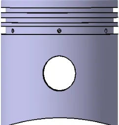
[image:2.612.326.491.74.273.2] [image:2.612.144.265.320.447.2]The finite element analysis to the piston is to establish the reasonable and accurate finite element model first, thus carrying out analysis by marking cell grids to obtain the accurate results finally. According to the structural symmetry of the piston, in order to be convenient for calculation and decrease workload, cut the established piston model to maintain 1/4 and then import the model to the finite element software for the finite element analysis to the piston according to the fine interface between the modeling software and the finite element analysis software. During the importing process, some details have been omitted, such as the chamfer and the snap ring of the piston pin etc. The geometrical model for the piston is as shown in Figure 1.
Figure 1: Geometrical Model For The Piston
2.2 Physical Properties of the Material
Table 1: Parameters Of The Piston Material Parameters Values of the parameters
Piston material Aluminum alloy
Poisson ratio 0.32
Elastic modulus of the piston 70GPa
Material density 2700
kg
/ m
3Conductivity factor 160w/(m2⋅K)
Coefficient of thermal expansion 21×10−6m /K
2.3 Mesh Generation
[image:2.612.77.304.515.629.2]During the mesh generation for the piston model, based on experiences and with several trials, the eight-node hexahedron cell SOLID70 is selected in this paper. Figure 2 shows the final finite element model after mesh generation for the piston.
Figure 2: Mesh Generation For The Piston
3. THERMAL LOAD ANALYSIS TO THE PISTON
3.1 Fundamental of Thermal Analysis
The stable thermal load means that the temperature field of the piston remains unchanged during the working process of the piston and that the heat flowing from the gas to through the piston top equals that discharged from the ring zone, the skirt and the cooling chamber of the piston etc. The heat of the gas and the piston top mostly come from heat convection of the gas and the piston top, the heat transfer within the piston abides by Fourier Law and no heat can occur within the piston itself, so the thermal analysis to the piston is a stable thermal analysis to the problem without any internal heat source.
Fourier Law is the basis for the heat conduction theory, and the vector expression for the Fourier Law is:
gradT
k
q
=
−
×
(1)Where,q—heat flux, which is a the vector in
2
/ m
w ;
k—the heat conduction coefficient of the material treated as the constant, in w/(m⋅K);
gradT— the temperature gradient, also
a vector, in
°
C /
m
.Where, the negative sign means that the
direction of q is always opposite to that of gradT.
∂
∂
×
−
=
∂
∂
×
−
=
∂
∂
×
−
=
∂
∂
×
−
=
n
T
k
q
z
T
k
q
y
T
k
q
x
T
k
q
n z y x(2)
where, :n—the exterior normal direction vector of the object at any boundary.
From Equation (2) we can get that when the
direction of the gradient component x T ∂ ∂
is opposite
to x-axial and x T ∂
∂ is negative, q
x is positive,
indicating that qx is in the same direction with
x-axial; or else, when x T ∂
∂ is in the same direction with
x-axial, qx is negative indicating that the heat flow is in the opposite direction to x-axial.
Based on the fundamental of heat transfer and abiding by the law of conservation of energy, we can get that the differential equation for solid heat conduction is as follows:
ρ
ω
α
c
z
T
y
T
x
T
t
T
+
∂
∂
+
∂
∂
+
∂
∂
=
∂
∂
2 2 2 2 2 2(3)
Where,
α
—the heat conduction coefficient,ρ
α
c
k
=
, inm /
2s
;c— the specific heat at constant pressure of the
material, treated as a constant in J/kg⋅°C;
ω
— the internal heat source intensity of thematerial, in
W
/ m
3.If the solid is in the adiabatic condition:
0
2 2 2 2 2 2=
∂
∂
+
∂
∂
+
∂
∂
z
T
y
T
x
T
The the temperature rise of the solid in this condition is called the adiabatic temperature rise,
written as
θ
, and from Equation (3) we can get:c
t
ρ
ω
θ
=
∂
∂
(4)With Equation (4), the heat conduction equation can be expressed as:
0 2 2 2 2 2 2 = ∂ ∂ − ∂ ∂ + ∂ ∂ + ∂ ∂ + ∂ ∂ t T t z T y T x T θ
α (5)
If no change occurs to the temperature in z
direction, which means that ∂∂Tz , the temperature
field is a plane problem and the heat conduction equation can be simplified as:
0 2 2 2 2 = ∂ ∂ − ∂ ∂ + ∂ ∂ + ∂ ∂ t T t y T x T θ
α (6)
After long-term heat exchange, the temperature will no longer change with the time, thus getting:
0
=
∂
∂
=
∂
∂
t
T
t
θ
This kind of temperature field which does not change with the time is the stable temperature field.
With Equation (6), the heat conduction equation can be simplified as:
0 2 2 2 2 2 2 = ∂ ∂ + ∂ ∂ + ∂ ∂ z T y T x
T (7)
The heat conduction equation establishes the relationship of the temperature with the time and space, but there are indefinite solutions for the heat conduction equation; in order to determine the unique solution for the differential equation of the solid, the boundary condition and the initial condition must considered when understanding the actual temperature distribution with the solid. In the general description, we collectively call the boundary condition and the initial condition as the definite condition and simultaneously solve the differential equation for heat conduction, thus obtaining the temperature distribution within the solid.
3.2 Thermal Stress Analysis to the Piston
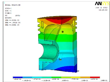
The temperature field analysis to the piston is as shown in Figure 3 and Figure 4. Through the analysis, we can get that the temperature field distribution is basically reasonable. Then carry out a thermal stress analysis according to the temperature field of the piston. In the thermal stress analysis, it is necessary to convert thermal units within ANSYS to structural units and thermal units of solid 70 to structural units of solid45. After conversion, the thermal stress analysis can be carried out .
During the thermal stress analysis, it is necessary to make sure that no rigid body displacement will occur to the model. So it is necessary to carry out constraint to the piston in every direction, and the constraint applied cannot bring in additional mechanical load. The applied temperature load during the thermal stress analysis is the temperature load when the result for the temperature field automatically converts to nodes.
considering the actual condition, apply constraint in Z direction within the piston pin boss. With the application of the aforesaid loads, carry out the thermal stress analysis to the 1/4 model of the piston with the definite-element software, thus obtaining the thermal stress distribution nephogram of the model, as shown in Figure 4.
[image:4.612.99.288.185.324.2]Figure 3: Temperature Field At The External Surface Of The Piston
Figure 4: Temperature Field Within The Piston
[image:4.612.99.291.352.697.2]
Figure 5: Thermal Stress Nephogram At The External Surface Of The Piston In The Direction Of
Z-Axial
Figure 6: Thermal Stress Nephogram Within The Piston In The Direction Of Z-Axial
The stress distribution nephogram of the piston in the direction of A-axial is as shown in Figures 5 and 6. Seen from the figure, the maximum stress for the piston is 139MPa and the part with rapid change of the stress occurs within the oil hole. The reason for this phenomenon is that the oil hole chamfer is omitted in the import procedure of the model, thus causing the stress concentration. The allowable stress of the piston is greater than the maximum stress applied to the piston in the direction of Z-axial. Besides, in actual condition, the existence of the rounded corner will further decrease the stress value, thus mitigating the stress, so that the overall stress distribution of the piston is reasonable.
3.3 Thermal Deformation Analysis to the Piston Thermal deformation of the piston occurring in the temperature load is as shown in Figure 6.
Figure 7: Thermal Deformation Of The Piston
[image:4.612.321.509.486.626.2]indicating that different expansion deformation will
occur to the same material in different
temperatures.
4. THERMAL LOAD AND MECHANICAL LOAD COUPLING ANALYSIS TO THE PISTON
[image:5.612.100.286.403.525.2]4.1 Mechanical load analysis to the piston In the gas pressure which is subjected to periodic change, the mechanical load to the piston is really great, during the working process it can cause great impact to the entire combustion engine and the generated stress and deformation will influence the fatigue life and reliability of the piston. The mechanical load to the piston during the working process includes: the working medium pressure within the cylinder, the piston inertia force, the bearing reaction force of the interior surface of the pin boss hole and the lateral pressure of the skirt. At the maximum explosion pressure within the cylinder, the pressure to the piston is maximum and the force to and the deformation of the piston is maximum, so it is of great importance to analyze the piston intensity at this moment.
Figure 8: Displacement Nephogram Of The Piston
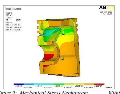
Figure 9: Mechanical Stress Nephogram Within The Piston In The Direction Of Z- Axial
Known from Figure 8, the deformation at the
center of the piston top is maximum,decreasing
gradually from the interior to the exterior, because the maximum explosion pressure of the mechanical load acts on the piston top with the maximum deformation of 0.0342mm and the head style of the piston after being deformed will not cause the piston interfered within the cylinder, thus preventing from affecting the normal operation of the engine. Thus the deformation of the piston is minimum with the maximum explosion pressure, so that the piston will not get damaged. From Figure 9, the stress concentration parts of the piston are distributed within the piston pin boss and the point where the pin boss contacts the inner cylinder, with the maximum stress in the forward direction is 16.6MPa. The stress concentration occurs because displacement constraint is applied to this part, thus the stress is changed sharply and in the meantime, no rounded corner treatment is carried out during the import procedure of the model; in the actual condition, the stress within the piston structure will be smaller, thus the piston is safe.
4.2 Thermo-Mechanical Coupling Analysis To The Piston
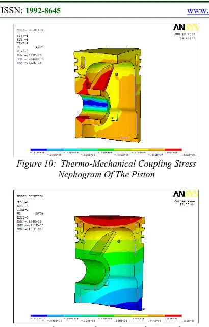
[image:5.612.98.293.544.697.2]Figure 10: Thermo-Mechanical Coupling Stress Nephogram Of The Piston
Figure 11: Thermo-Mechanical Coupling Displacement Nephogram Of The Piston In The Direction Of Z-Axial
From figure 10, we can get the thermo-mechanical coupling condition of the piston and that the stress concentration occurs at the piston pin boss and the ribbed plate, with the maximum value in the forward direction of 62.2MPa, which is 250MPa smaller than the allowable stress of the piston, so the piston is safe. But with the combined effect of the thermal load and mechanical load, the thermal load plays the main role.
From Figure 10, we can get that with the combined effect of thermo-mechanical coupling, the maximum deformation of the piston occurs at the piston top with the maximum value of 0.132mm. In comparison with the displacement deformation of the piston with the individual effect of the mechanical load and thermal load, with the combine effect of the temperature and mechanical load, the maximum deformation is mainly caused by deformation due to thermal expansion, and the temperature plays the main role. The deformation at this time is rather small, causing no damage to the piston.
5. CONCLUSION
With the thermal stress and the mechanical stress analysis to the piston, we can get the stress
distribution and the deformation condition for each part of the piston. The maximum thermal stress of the piston is 139MPa and the maximum mechanical stress is 16.6MPa. The maximum deformation under the effect of the thermal stress is 0.166mm and the maximum deformation under the effect of the mechanical stress is 0.0324mm. With the thermo-mechanical coupling analysis, we can get that the maximum of the stress to the piston is 62.2MPa, the maximum deformation is 0.132mm, and the stress and deformation are both within the allowable range, so the piston is safe. The deformation and the stress of the piston are mainly determined by the temperature, so it is necessary to decrease the piston temperature through structure improvement, e.g. by using the combined piston with small heat conduction coefficient and large heat conduction coefficient of the skirt and inner cylinder.
REFERENCES:
[1] P. O’Haraa, , C.A. Duartea, T. Easonb,
“Generalized finite element analysis of three-dimensional heat transfer problems exhibiting sharp thermal gradients”, Computer Methods in
Applied Mechanics and Engineering, Vol.
198, No. 21-26, 2009, pp. 1857-1871.
[2] V. Ucar, A. Ozel, “Use of the finite element
technique to analyze the influence of coating materials, material phase state and the purity on the level of the developed thermal stresses in plasma coating systems under thermal loading conditions”, Surface and Coatings
Technology, Vol. 142-144, 2001, pp. 950 -953.
[3] Jarruwat Chareonsuk, Passakorn Vessakosol ,
“Numerical solutions for functionally graded solids under thermal and mechanical loads using a high-order control volume finite
element method”, Applied Thermal
Engineering, Vol. 31, No. 2-3, 2011, pp. 213 -227.
[4] Douglas M. Baker, Dennis N. Assanis, “A
methodology for coupled thermodynamic and heat transfer analysis of a diesel engine”,
Applied Mathematical Modelling, Vol. 18, No.
11, 1994, pp. 590-601.
[5] U.A. Benz,J.J. Rencis , “Coupling
two-dimensional and axisymmetric boundary
element zones for transient heat transfer
applications”, Engineering Analysis with
Boundary Elements, Vol. 26, No. 5, 2002, pp.
[6] Bao-Lin Wang,Yiu-Wing Mai , “Transient one-dimensional heat conduction problems solved by finite element”, International
Journal of Mechanical Sciences, Vol. 47, No.
2, 2005, pp. 303–317.
[7] Elisa Carvajal Trujillo, Francisco J.
Jiménez-Espadafor, José A. Becerra Villanueva, Miguel Torres Garcí, “A Methodology for the
estimation of cylinder inner surface
temperature in an air-cooled engine”, Applied
Thermal Engineering, Vol. 31, No. 8-9, 2011,
pp. 1474-1481.
[8] Sook-Ying Ho, Allan Paull , “Coupled thermal,
structural and vibrational analysis of a hypersonic engine for flight test”, Aerospace
Science and Technology, Vol. 10, No. 5, 2006,
pp. 420-426.
[9] Douglas M. Baker, Dennis N. Assanis, “A
methodology for coupled thermodynamic and heat transfer analysis of a diesel engine”,
Applied Mathematical Modelling, Vol. 18, No.
11, 1994, pp. 590-601.
[10] C.D. Rakopoulos, G.C. Mavropoulos,
“Components heat transfer studies in a low heat rejection DI diesel engine using a hybrid
thermostructural finite element model”,
Applied Thermal Engineering, Vol. 18, No. 5,
1988, pp. 301-316.
[11] R. Keribar, T. Morel, “Methods for
thermomechanical analysis of thermal barrier coatings in diesel engines”, Surface and
Coatings Technology, Vol. 30, No. 1, 1987,